
 My Inquiry
 My Account


Texas Instruments PCA9545AGQNR
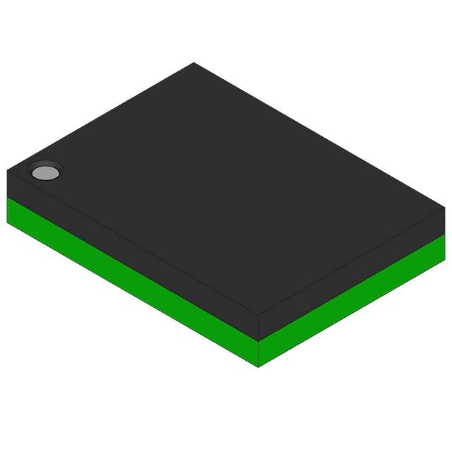
- Part No.:
- PCA9545AGQNR
- Manufacturer:
- Texas Instruments
- Category:
- Specialized
- Package:
- 20-VFBGA
- Datasheet:
-
 PCA9545AGQNR.pdf
- Description:
- IC INTERFACE SPECIALIZED 20BGA
- Quantity:
- Payment:

- Shipping:

Inventory:2,365
Please send an inquiry. Send us your inquiry, and we will respond immediately.
Product details
Overview
PCA9545AGQNR from Texas Instruments is a low-voltage 4-channel I²C and SMBus switch with interrupt logic and reset functionality. It functions as a bidirectional translating multiplexer that routes one upstream SCL/SDA pair to any combination of four downstream SCn/SDn channels. Key confirmed parameters include 2.3 V to 5.5 V operating supply, 0–400 kHz clock support, 5.5 V tolerant inputs, active-low RESET and INT outputs, and 4-channel interrupt aggregation (INT3–INT0 → INT). It is used in server backplanes to resolve I²C slave address conflicts among identical temperature sensors.
For engineers reviewing the PCA9545AGQNR datasheet, PCA9545AGQNR pinout, PCA9545AGQNR application, or PCA9545AGQNR equivalent, this page delivers verified technical context on channel selection via I²C control register, voltage-level translation between 1.8-V/2.5-V/3.3-V and 5-V buses, interrupt handling logic, reset recovery behavior, and TSSOP-20 package constraints - all critical for embedded system bus architecture and fault-tolerant I²C design.
Technical Context
The PCA9545AGQNR implements a programmable 1-of-4 bidirectional translating switch controlled by an 8-bit I²C-accessible control register, where bits B0–B3 select active channels and bits B4–B7 reflect real-time interrupt status per channel. Its pass-gate architecture uses VCC as voltage-limiting reference, enabling level translation without external level shifters.
Interrupt logic performs wired-AND aggregation: any asserted INTn (active-low) pulls the open-drain INT output low, while the corresponding bit in the control register latches the event. The active-low RESET input forces full state-machine reset and channel deselection, independent of I²C communication - essential for recovering stuck-bus conditions on downstream channels.
Key Specifications
| Parameter | Value and Actual Design Meaning |
|---|---|
| Supply Voltage | 2.3 V to 5.5 V - supports mixed-voltage I²C domains including 1.8-V, 2.5-V, 3.3-V, and 5-V slaves on separate channels. |
| I²C Clock Frequency | 0 to 400 kHz - compatible with Standard-Mode and Fast-Mode I²C, enabling use in high-speed sensor or PMBus applications. |
| Channel Count | 4 independent bidirectional SCn/SDn channels - allows simultaneous or selective routing to up to four isolated I²C sub-buses. |
| Interrupt Inputs | Four active-low INT3–INT0 inputs - each monitors one downstream channel; no channel activation required for interrupt detection. |
| Reset Function | Active-low RESET with 6 ns minimum pulse width - fully resets internal state machine and deselects all channels, recovering from bus lockup. |
| Input Tolerance | 5.5 V tolerant on all I/O pins - eliminates need for external clamping diodes when interfacing higher-voltage peripherals. |
| On-State Resistance | Typ. 7 Ω at 2.5 V, max 45 Ω at 2.3 V - ensures minimal signal degradation and timing skew across translated I²C paths. |
Pinout & Package
GQN package: 20-pin TSSOP (6.50 mm × 4.40 mm), lead pitch 0.65 mm, exposed pad not electrically connected. Pin numbering follows TI standard top-view orientation.
| Pin/Terminal | Circuit Role | Design Meaning |
|---|---|---|
| A0 | Hardware address LSB | Configures device I²C slave address (0x70–0x73); must be tied to VCC or GND - no floating connections allowed. |
| A1 | Hardware address MSB | Combines with A0 to set one of four unique I²C addresses on shared bus; enables up to four PCA9545AGQNR devices on same master. |
| RESET | Active-low asynchronous reset | Forces immediate channel deselection and I²C state-machine reset; requires external pull-up to VCC; voltage must not exceed VCC to avoid reverse current. |
| INT | Open-drain interrupt output | Wired-AND of INT3–INT0; drives low when any downstream channel asserts interrupt; requires external pull-up resistor to master-side VDPUM. |
| INT0–INT3 | Active-low interrupt inputs | Each connects to one downstream I²C slave's INT pin; latched into control register bits B4–B7 for software identification of interrupt source. |
| SDA/SCL | Upstream I²C interface | Connects to master microcontroller; requires external pull-up to VDPUM (master-side voltage reference). |
| SD0–SD3 / SC0–SC3 | Downstream I²C channel pairs | Each SDn/SCn pair connects to one isolated slave sub-bus; requires dedicated pull-up resistors to respective VDPUx voltages for level translation. |
| VCC/GND | Power and reference | VCC sets maximum pass-through voltage and powers internal logic; GND provides return path; both must be decoupled locally with 100 nF ceramic capacitor. |
Key Features
| Feature | Design Value |
|---|---|
| 1-of-4 bidirectional translating switch | Enables single I²C master to manage four electrically isolated slave domains with independent voltage levels (e.g., 1.8-V sensors + 5-V EEPROMs) without signal contention. |
| Programmable channel selection | Controlled via single 8-bit I²C register (B0–B3); supports any combination of channels active simultaneously - simplifies dynamic bus reconfiguration in firmware. |
| Per-channel interrupt monitoring | Four dedicated INTn inputs feed latched status bits (B4–B7) in control register - allows master to identify interrupt source without polling individual slaves. |
| Hot-insertion support | No glitch on power-up and robust reset recovery ensure safe insertion/removal of downstream I²C modules during system operation - critical for modular server and telecom equipment. |
| Low standby current | Max 1 μA at 2.7 V - reduces quiescent power in always-on management controllers and battery-backed systems. |
Applications
| Server Backplane Management | Rack-Mount Telecom Switching |
|---|---|
Use Scenario: Multiple identical temperature sensors (e.g., TMP102) share same I²C address on different blades of a 19-inch server rack. IC Role / Device Role / Timing Role: PCA9545AGQNR acts as address-conflict resolver by isolating each sensor group onto separate SCn/SDn channels, enabling sequential polling via I²C register writes. Use Value: Eliminates need for hardware address jumpers or sensor firmware modification; reduces BOM count and improves thermal monitoring scalability across 10+ blade servers. | Use Scenario: Line cards in a carrier-grade router require independent I²C access to power monitors, fan controllers, and PHY registers without bus contention. IC Role / Device Role / Timing Role: PCA9545AGQNR serves as channelized I²C gateway, allowing central management CPU to access per-card peripherals through dedicated downstream channels. Use Value: Enables hot-swap-safe card insertion; prevents cross-talk during card replacement; supports deterministic latency for real-time fan speed control loops. |
| Factory Automation PLC I/O Modules | Multi-Sensor IoT Edge Gateway |
Use Scenario: Programmable logic controller (PLC) base unit connects to eight I²C-based analog input modules, each containing identical ADCs with fixed 0x48 address. IC Role / Device Role / Timing Role: PCA9545AGQNR functions as I²C channel selector, assigning each module to its own SCn/SDn pair and using INTn lines to flag over-range events. Use Value: Provides deterministic interrupt response time (<4 μs propagation delay); avoids software polling overhead; supports modular expansion up to four modules per switch. | Use Scenario: Edge gateway aggregates data from environmental sensors (humidity, pressure, gas) and actuator drivers, all sharing limited I²C bandwidth and conflicting addresses. IC Role / Device Role / Timing Role: PCA9545AGQNR operates as intelligent I²C traffic manager, dynamically enabling only active sensor channels and aggregating interrupts to reduce host wake-ups. Use Value: Extends battery life via selective channel activation; enables firmware-based priority arbitration; maintains <100 ns timing margin for 400 kHz Fast-Mode operation. |
Equivalent & Alternatives
The following parts are listed as comparable options for similar I²C bus switching applications.
| Alternative Part | Technical Difference | Application Difference | Selection Advice |
|---|---|---|---|
| PCA9544APW | 4-channel I²C switch without interrupt aggregation; no INT3–INT0 inputs or INT output; identical control register structure and voltage specs. | Suitable only where interrupt monitoring is handled externally or unnecessary; lacks hardware-assisted interrupt source identification. | Select PCA9544APW if interrupt consolidation adds no value and cost reduction is prioritized; verify external interrupt polling logic exists. |
| TCA9544APWR | Pin-compatible 4-channel I²C switch with identical package and pinout; includes interrupt logic but uses different control register mapping (INT bits in separate status register). | Requires firmware adaptation for interrupt readback; shares same voltage range and translation capability but differs in register-level interrupt handling. | Choose TCA9544APWR only when migrating from legacy PCA9545A designs with minor register updates; confirm INT timing compatibility with host ISR latency. |
Compared with PCA9545AGQNR, PCA9544APW omits interrupt logic entirely - reducing component count but requiring software polling - while TCA9544APWR retains interrupt functionality yet mandates register-level firmware changes due to non-identical control register layout and interrupt status access method.
Availability
PCA9545AGQNR is available at Aetrix Electronics and suitable for server backplane management, rack-mount telecom switching, and factory automation PLC I/O modules requiring stable component supply, long-term lifecycle assurance, and traceable sourcing.
Supply support for PCA9545AGQNR includes scheduled delivery planning, volume procurement assistance, BOM continuity management, traceable sourcing, and lifecycle availability coordination for OEM customers, industrial embedded developers, connected-device designers, and electronics production programs.
Manufacturer
Texas Instruments is a global semiconductor company headquartered in Dallas, Texas, delivering analog and embedded processing solutions for industrial, automotive, and communications markets.
The PCA9545A product line was designed specifically for I²C/SMBus bus expansion and conflict resolution in dense multi-slave systems, emphasizing robust reset recovery, voltage translation, and interrupt-aware channel management.
FAQ
What is the function of the RESET pin on the PCA9545AGQNR?
The RESET pin on the PCA9545AGQNR is an active-low asynchronous input that forces a full internal state-machine reset and deselects all four channels immediately. When asserted for ≥6 ns, it clears the control register to its default (all channels disabled), releases stuck SDA lines on downstream buses, and restores I²C communication integrity - critical for recovering from bus lockup without power cycling. This behavior is identical across all PCA9545AGQNR units and is documented in TI's SCPS147D datasheet section 7.7.
How does the PCA9545AGQNR handle I²C voltage-level translation between different bus domains?
PCA9545AGQNR enables voltage-level translation by using its VCC pin as the maximum pass-through voltage reference for all internal pass gates. External pull-up resistors on each SCn/SDn channel are connected to their respective domain voltages (e.g., 1.8 V for sensors, 5 V for EEPROMs), while the upstream SDA/SCL lines pull up to the master-side VDPUM. The device's 5.5 V tolerant I/O pins and low RON switches (≤45 Ω) ensure signal integrity across combinations like 1.8-V ↔ 5-V without external level shifters - a capability confirmed in datasheet sections 3 and 9.1.
Can multiple PCA9545AGQNR devices share the same I²C bus?
Yes, up to four PCA9545AGQNR devices can coexist on the same I²C bus using hardware-configurable slave addresses. Pins A0 and A1 determine the base address: A1A0 = 00 selects 0x70, 01 selects 0x71, 10 selects 0x72, and 11 selects 0x73. Each device responds only to its assigned address, enabling hierarchical bus expansion - for example, one PCA9545AGQNR managing four sensor clusters, each with its own downstream PCA9545AGQNR. This addressing scheme is defined in datasheet Figure 10 and section 9.6.1.
What is the purpose of the INT output and how does it relate to INT0–INT3 inputs on the PCA9545AGQNR?
The INT output on the PCA9545AGQNR is an open-drain active-low signal that functions as a wired-AND of the four INT0–INT3 inputs. When any downstream I²C slave asserts its INTn line (low), the PCA9545AGQNR pulls INT low and latches the event in bits B4–B7 of its control register. This allows the master to detect interrupt activity without polling and then read the register to identify the exact source channel - a feature validated in datasheet sections 2, 9.4, and Table 2. No channel selection is required for interrupt detection.
Does the PCA9545AGQNR support Fast-Mode I²C (400 kHz) operation?
Yes, the PCA9545AGQNR fully supports Fast-Mode I²C operation up to 400 kHz, as specified in datasheet section 7.5 and confirmed in the "Features" list. Its propagation delay (tpd) is ≤1 ns at CL = 50 pF (section 7.6), and its electrical characteristics - including VOL, VOH, and timing margins - are characterized across the full 0–400 kHz range under recommended operating conditions (VCC = 2.3 V to 5.5 V, TA = –40°C to 85°C). This makes PCA9545AGQNR suitable for time-critical applications such as PMBus-compliant power system management.
PCA9545AGQNR Specifications
- Product attributes
- Attribute value
- Manufacturer:
- Texas Instruments
- Series:
- -
- Package/Case:
- 20-VFBGA
- Packaging:
- Tape & Reel (TR)
- Product Status:
- Obsolete
- Applications:
- Translating Switch
- Interface:
- I2C, SMBus
- Voltage - Supply:
- 2.3V ~ 5.5V
- Supplier Device Package:
- 20-BGA MICROSTAR JUNIOR (4x3)
- Grade:
- -
- Qualification:
- -
- Mounting Type:
- Surface Mount
PCA9545AGQNR FAQ
1.How can I place an order for PCA9545AGQNR through Aetrix?
Please submit a Request for Quotation (RFQ) for PCA9545AGQNR on Aetrix. Our sales agent will provide a competitive quotation and guide you through the order confirmation once you accept the terms.
2.Are the price and stock information for PCA9545AGQNR reliable?
The price and inventory of PCA9545AGQNR are updated periodically and may fluctuate due to market conditions. Stock and pricing data are typically refreshed every 24 hours. Quotation validity for PCA9545AGQNR is usually 5 days.
3.What payment methods are accepted for PCA9545AGQNR?
We accept Wire Transfer, PayPal, Credit Card, Western Union, MoneyGram, and Escrow for PCA9545AGQNR transactions.
Note: Certain payment methods may incur a processing fee.
4.How is shipping managed for PCA9545AGQNR?
PCA9545AGQNR orders can be shipped via leading logistics carriers, including DHL, UPS, FedEx, TNT, or Registered Mail.
Once your PCA9545AGQNR order is processed, you will receive an email with the shipment details and tracking number.
Note: Tracking information may take up to 24 hours to appear. Express delivery typically takes 3–5 business days.
5.How can I obtain technical support or documentation for PCA9545AGQNR?
For technical support, including PCA9545AGQNR datasheets, pinout diagrams, or application guidance, please contact our engineering support team. They can provide detailed documentation and assistance for your PCA9545AGQNR requirements.
6.How does Aetrix verify that PCA9545AGQNR is sourced from the original manufacturer or authorized distributors?
All PCA9545AGQNR products on Aetrix are procured from qualified distributors and authorized channels. Our dedicated quality assurance team conducts strict verification, including traceability checks and, if necessary, third-party testing. This ensures that PCA9545AGQNR meets industry standards.
7.What is the process for return or replacement of PCA9545AGQNR?
All PCA9545AGQNR units undergo pre-shipment inspection (PSI). If there is an issue with PCA9545AGQNR, returns or replacements are accepted under the following conditions:
1.Quantity discrepancies, incorrect items, or visible external defects (such as breakage or corrosion), acknowledged by Aetrix.
2.The issue is reported within 90 days of delivery.
3.The PCA9545AGQNR part is unused and in its original packaging.
Return procedure for PCA9545AGQNR:
1.Submit a request within 90 days.
2.Obtain a Return Material Authorization (RMA) from Aetrix.
PCA9545AGQNR Tags

-
NVT4857UKAZ
NXP Semiconductors

-
TCA8418RTWR
Texas Instruments

-
PCA9546APWR
Texas Instruments

-
MD0100N8-G
Microchip Technology

-
PCA9548APW,118
NXP Semiconductors

-
PCA9540BDP,118
NXP Semiconductors

-
PCA9548APWR
Texas Instruments

-
PCA9546APW,118
NXP Semiconductors

-
PTN3360DBS,518
NXP Semiconductors

-
PCA9546ABS,118
NXP Semiconductors

-
PCA9518PWR
Texas Instruments

-
PCA9545APW,118
NXP Semiconductors
Tech Hub

A practical engineering guide to 3.3V and 5V logic compatibility, input thresholds, resistor dividers, translator ICs, MOSFET level shifting, I2C pull-ups, timing limits and power-sequencing risks.

The 74HC595 uses push-pull logic outputs, while the TPIC6B595 uses 50 V open-drain DMOS sinks for higher-power loads. This guide compares timing, current limits, 3.3 V interfacing, load wiring, thermal…

The 74HC595 converts serial data into eight stable parallel outputs. This guide covers pin functions, shift and storage timing, OE and MR behavior, drive-current limits, cascading, voltage compatibilit…

A technical comparison of level-sensitive latches and edge-triggered flip-flops, covering timing windows, setup and hold limits, master–slave operation, time borrowing, race-through, HDL inference and…

A D latch stores one bit while Enable controls when data can pass. This reference covers gate-level operation, truth tables, transparency, setup and hold timing, LE versus OE, common ICs and practical …

An SR latch stores one bit through cross-coupled feedback. This engineering reference covers NOR and NAND implementations, truth tables, forbidden-state recovery, gated operation, switch debouncing, fa…

Latch circuits retain one bit through feedback. This technical reference covers SR and D latches, truth tables, transparency, timing limits, latch-versus-flip-flop behavior, applications and common log…

An engineering guide to LED driver operation, constant-current and constant-voltage outputs, linear and switching topologies, dimming, IC selection, calculations, replacement compatibility, and fault c…

Operational amplifier guide covering op amp basics, feedback, ideal vs real op amps, common configurations, buffer circuits, offset, bias current, gain-bandwidth, slew rate, rail-to-rail limits and sel…

Jumper cables guide covering safe connection order, red and black clamp placement, final ground connection, cable gauge, length, clamp quality, copper vs CCA cables, jump starter comparison and battery…


