
 My Inquiry
 My Account


NXP Semiconductors PCA9956BTWY
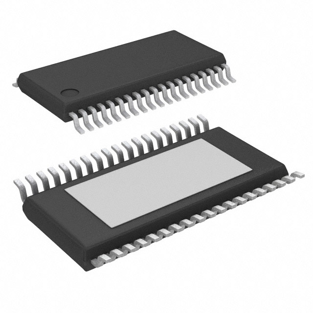
- Part No.:
- PCA9956BTWY
- Manufacturer:
- NXP Semiconductors
- Category:
- LED Drivers
- Package:
- 38-TFSOP (0.173", 4.40mm Width) Exposed Pad
- Datasheet:
-
 PCA9956BTWY.pdf
- Description:
- IC LED DRV LIN PWM 65MA 38HTSSOP
- Quantity:
- Payment:

- Shipping:

Inventory:12,531
Please send an inquiry. Send us your inquiry, and we will respond immediately.
Product details
Overview
The PCA9956BTWY from NXP Semiconductors is a 24-channel, I²C-bus controlled constant-current LED driver optimized for RGBA LED dimming and blinking in amusement products. It delivers up to 57 mA per channel with 20 V LED supply tolerance, features dual 8-bit PWM control (31.25 kHz individual + 122 Hz group), and supports hardware blinking via active-low OE pin.
For engineers reviewing the PCA9956BTWY datasheet, PCA9956BTWY pinout, PCA9956BTWY application, or PCA9956BTWY equivalent, key selection criteria include its 24-channel sink architecture, Fast-mode Plus (1 MHz) I²C interface, thermal/short/open-load diagnostics, programmable group/sub-call addressing, and HTSSOP38 package with exposed thermal pad.
Technical Context
The PCA9956BTWY integrates an internal 8 MHz oscillator and uses a two-tiered PWM architecture: 24 independent 8-bit channels at 31.25 kHz for per-LED brightness control, plus a shared 8-bit group controller supporting adjustable blink frequency (15 Hz to 16.8 s period) and 0–99.6% duty cycle. Its output current is set by an external REXT resistor and digitally trimmed via 24 dedicated IREF registers.
Control logic includes software reset (SWRST), power-on reset, noise-filtered SDA/SCL inputs, and register auto-increment modes for efficient bulk writes. Error detection (open/short load, overtemperature) is reported through dedicated EFLAG registers readable over I²C, while thermal shutdown protects against junction temperature exceedance.
Key Specifications
| Parameter | Value and Actual Design Meaning |
|---|---|
| LED Channels | 24 constant-current sink outputs, each programmable for off/on/PWM/brightness+group mode |
| Max Output Current | 57 mA per channel, adjustable from 225 µA to 57 mA via 8-bit linear DAC and REXT |
| PWM Frequency | Individual: fixed 31.25 kHz; Group: fixed 122 Hz or programmable 15 Hz to 16.8 s period |
| I²C Interface | Fast-mode Plus (Fm+) compliant, up to 1 MHz, with 30 mA SDA drive strength for high-capacitance buses |
| Supply Range | VDD = 3.0 V to 5.5 V; LED supply up to 20 V (sink configuration) |
| Operating Temp | −40 °C to +85 °C ambient; thermal shutdown activates above process-limited junction temperature |
| Accuracy | ±4 % current matching between channels; ±6 % device-to-device output current variation |
Pinout & Package
Package: HTSSOP38 (SOT1331-1), 38-pin thermally enhanced thin shrink small outline package with 0.5 mm pitch and exposed center thermal pad connected to VSS.
| Pin/Terminal | Circuit Role | Design Meaning |
|---|---|---|
| REXT (1) | Current set reference input | Connects external resistor to ground to define full-scale output current (225 µA–57 mA range) |
| AD0–AD2 (2–4) | Quinary hardware address inputs | Each accepts GND/PD/FLT/PU/VDD for 125 unique I²C slave addresses (no pull-up resistors required) |
| OE (5) | Active-low output enable | Hardware blink/dim control; overrides all LED states when asserted low |
| LED0–LED23 (6–13,15–20,22–24,26–33) | Constant-current LED sink outputs | 24 individually controllable channels; tolerate up to 20 V when OFF; support PWM dimming and delay programming |
| RESET (35) | Active-low hardware reset | Asynchronous reset with external 10 kΩ pull-up; initializes registers to default state (all LEDs OFF) |
| SCL/SDA (36/37) | I²C serial clock/data | Fm+ interface pins with integrated noise filters; SDA supports 30 mA drive for bus capacitance up to 4000 pF |
| VDD (38) | Power supply input | 3.0 V to 5.5 V digital/analog supply; powers internal oscillator, logic, and drivers |
| VSS (14,18,21,25,34) + thermal pad | Ground reference | All VSS pins and exposed pad must be connected to system ground; thermal pad requires soldering and vias for thermal performance |
Key Features
| Feature | Design Value |
|---|---|
| 24-channel independent PWM control | 8-bit resolution (256 steps) at 31.25 kHz enables precise, flicker-free brightness tuning per LED |
| Programmable group dimming/blinking | 8-bit group PWM with selectable frequency (15 Hz–16.8 s) allows synchronized visual effects across all 24 channels |
| Hardware blink/dim via OE pin | Active-low OE enables external PWM control without I²C traffic-critical for multi-device synchronization |
| 125-device I²C addressing | Three quinary AD pins (GND/PD/FLT/PU/VDD) yield 5³ = 125 unique slave addresses on one bus |
| Diagnostic feedback | On-chip open/short load and overtemperature detection with register-accessible error flags (EFLAG0–EFLAG5) |
| Software Reset (SWRST) | I²C-commanded reset replicates Power-On Reset behavior-reinitializes all registers to defaults without power cycle |
Applications
| Amusement Lighting Control | RGB/RGBA LED Displays |
|---|---|
Use Scenario: Dynamic lighting in arcade cabinets, prize wheels, and interactive game panels requiring synchronized color transitions and blinking sequences. IC Role / Device Role / Timing Role: 24-channel constant-current sink driving discrete RGBA LEDs with independent brightness and coordinated group blink timing. Use Value: Eliminates need for external MOSFETs or current-limiting resistors; enables smooth 31.25 kHz PWM dimming and programmable 15 Hz–16.8 s group blink for attention-grabbing effects. |
Use Scenario: Full-color signage and decorative displays using RGB or RGBA LED arrays where uniform color mixing and intensity control are critical. IC Role / Device Role / Timing Role: Per-channel current regulation and dual-level PWM (individual + group) for accurate color point maintenance and global intensity scaling. Use Value: ±4% channel-to-channel current matching ensures consistent luminance across pixels; group PWM allows real-time white-point adjustment without recalibrating individual channels. |
| Keypad & Status Backlighting | Industrial HMI Panels |
Use Scenario: Backlighting for membrane keypads and status indicators in handheld devices and consumer electronics requiring low-power, reliable illumination. IC Role / Device Role / Timing Role: Constant-current driver with hardware OE control enabling rapid on/off cycling and low-duty-cycle blinking for battery-sensitive applications. Use Value: Active-low OE pin permits external microcontroller PWM dimming at any frequency-extending battery life while maintaining visual clarity. |
Use Scenario: Operator interface panels in factory automation systems needing robust LED indication under wide temperature (-40°C to +85°C) and EMI-prone conditions. IC Role / Device Role / Timing Role: Fault-tolerant LED driver with built-in open/short load detection and thermal shutdown for unattended operation. Use Value: Real-time error flag registers (EFLAG0–EFLAG5) allow firmware to detect and isolate failed LEDs without external sensing circuitry. |
Equivalent & Alternatives
The following parts are listed as comparable options for similar 24-channel constant-current LED driver applications.
| Alternative Part | Technical Difference | Application Difference | Selection Advice |
|---|---|---|---|
| TLC5947 | 24-channel, 12-bit PWM (4096 steps), 30 MHz SPI interface, no I²C, max 120 mA/channel | Requires SPI host; higher resolution but no group blink or diagnostic registers | Choose TLC5947 for higher PWM resolution and higher current needs; avoid if I²C bus integration or fault reporting is required |
| IS31FL3731 | 28-channel, I²C, 8-bit PWM at 1.3 kHz, integrated frame buffer, no group blink, max 40 mA/channel | Lacks programmable group blink frequency and open/short load detection; optimized for matrix scanning | Choose IS31FL3731 for LED matrix applications with frame buffering; PCA9956BTWY preferred for discrete RGBA string control with diagnostics |
Compared with TLC5947 and IS31FL3731, the PCA9956BTWY uniquely combines I²C-based group blink programmability (15 Hz–16.8 s), on-die open/short/thermal diagnostics, and hardware OE synchronization-making it optimal for amusement and industrial status lighting where reliability and visual coordination are prioritized over raw resolution or matrix support.
Availability
The PCA9956BTWY is available at Aetrix Electronics and suitable for amusement lighting control, RGB/RGBA LED displays, keypad backlights, and industrial HMI panels requiring stable component supply and long-term production continuity.
Supply support for PCA9956BTWY includes scheduled delivery planning, volume procurement assistance, BOM continuity management, traceable sourcing, and lifecycle availability coordination for OEM customers, industrial embedded developers, connected-device designers, and electronics production programs.
Manufacturer
NXP Semiconductors is a global semiconductor company specializing in secure connectivity solutions for automotive, industrial, and IoT applications, with leadership in interface, power management, and LED driver ICs.
The PCA9956BTWY belongs to NXP's PCA99xx family of I²C-controlled LED drivers, designed specifically for high-reliability, multi-channel RGBA lighting in entertainment and human-machine interface systems.
FAQ
What is the maximum LED supply voltage supported by the PCA9956BTWY?
The PCA9956BTWY LED outputs are constant-current sinks rated for up to 20 V when in the OFF state. This allows direct connection to common 12 V or 24 V LED strings without external voltage translation, provided the VDD supply remains within 3.0 V to 5.5 V. The 20 V rating ensures safe operation during transient conditions and simplifies board-level power architecture for multi-voltage systems.
How does the PCA9956BTWY handle LED fault detection?
The PCA9956BTWY integrates on-die open-load, short-load, and overtemperature detection circuits. Fault status is reported through five dedicated read-only EFLAG registers (EFLAG0–EFLAG5), each covering a subset of the 24 LED channels. These flags are accessible via the I²C interface, enabling firmware to identify and isolate faulty LEDs without external sensing components-critical for maintenance-free operation in amusement and industrial applications.
Can multiple PCA9956BTWY devices be synchronized for simultaneous blinking?
Yes. The PCA9956BTWY supports hardware synchronization via its active-low OE (Output Enable) pin. Driving OE low across multiple devices simultaneously forces all LED outputs to blink in unison, independent of I²C commands. This eliminates timing skew and software overhead-enabling precise visual coordination in large-scale installations like arcade cabinets or architectural lighting arrays.
What is the purpose of the REXT pin on the PCA9956BTWY?
The REXT pin on the PCA9956BTWY connects to an external resistor that sets the full-scale output current for all 24 channels. By selecting an appropriate resistor value (e.g., 10 kΩ yields ~57 mA), designers establish the current range (225 µA to 57 mA) before fine-tuning individual channels via the 8-bit IREF registers. This analog calibration step ensures predictable, repeatable LED brightness across production units.
Does the PCA9956BTWY support both individual and group PWM control simultaneously?
Yes. Each of the 24 LED outputs can operate in four modes: OFF, ON (DC), individual PWM (31.25 kHz), or combined individual + group PWM. When both are active, the group PWM duty cycle modulates the amplitude of the individual PWM waveform-enabling layered effects such as pulsing brightness (group) overlaid on static color balance (individual). This dual-PWM architecture is explicitly defined in the PCA9956BTWY datasheet and verified in functional testing.
PCA9956BTWY Specifications
- Product attributes
- Attribute value
- Manufacturer:
- NXP Semiconductors
- Series:
- -
- Package/Case:
- 38-TFSOP (0.173", 4.40mm Width) Exposed Pad
- Packaging:
- Tape & Reel (TR)
- Product Status:
- Active
- Type:
- Linear
- Topology:
- -
- Internal Switch(s):
- Yes
- Number of Outputs:
- 24
- Voltage - Supply (Min):
- 3V
- Voltage - Supply (Max):
- 5.5V
- Voltage - Output:
- -
- Current - Output / Channel:
- 65mA
- Frequency:
- -
- Dimming:
- PWM
- Applications:
- Backlight
- Operating Temperature:
- -40°C ~ 85°C (TA)
- Grade:
- -
- Qualification:
- -
- Mounting Type:
- Surface Mount
- Supplier Device Package:
- 38-HTSSOP
PCA9956BTWY FAQ
1.How can I place an order for PCA9956BTWY through Aetrix?
Please submit a Request for Quotation (RFQ) for PCA9956BTWY on Aetrix. Our sales agent will provide a competitive quotation and guide you through the order confirmation once you accept the terms.
2.Are the price and stock information for PCA9956BTWY reliable?
The price and inventory of PCA9956BTWY are updated periodically and may fluctuate due to market conditions. Stock and pricing data are typically refreshed every 24 hours. Quotation validity for PCA9956BTWY is usually 5 days.
3.What payment methods are accepted for PCA9956BTWY?
We accept Wire Transfer, PayPal, Credit Card, Western Union, MoneyGram, and Escrow for PCA9956BTWY transactions.
Note: Certain payment methods may incur a processing fee.
4.How is shipping managed for PCA9956BTWY?
PCA9956BTWY orders can be shipped via leading logistics carriers, including DHL, UPS, FedEx, TNT, or Registered Mail.
Once your PCA9956BTWY order is processed, you will receive an email with the shipment details and tracking number.
Note: Tracking information may take up to 24 hours to appear. Express delivery typically takes 3–5 business days.
5.How can I obtain technical support or documentation for PCA9956BTWY?
For technical support, including PCA9956BTWY datasheets, pinout diagrams, or application guidance, please contact our engineering support team. They can provide detailed documentation and assistance for your PCA9956BTWY requirements.
6.How does Aetrix verify that PCA9956BTWY is sourced from the original manufacturer or authorized distributors?
All PCA9956BTWY products on Aetrix are procured from qualified distributors and authorized channels. Our dedicated quality assurance team conducts strict verification, including traceability checks and, if necessary, third-party testing. This ensures that PCA9956BTWY meets industry standards.
7.What is the process for return or replacement of PCA9956BTWY?
All PCA9956BTWY units undergo pre-shipment inspection (PSI). If there is an issue with PCA9956BTWY, returns or replacements are accepted under the following conditions:
1.Quantity discrepancies, incorrect items, or visible external defects (such as breakage or corrosion), acknowledged by Aetrix.
2.The issue is reported within 90 days of delivery.
3.The PCA9956BTWY part is unused and in its original packaging.
Return procedure for PCA9956BTWY:
1.Submit a request within 90 days.
2.Obtain a Return Material Authorization (RMA) from Aetrix.
PCA9956BTWY Tags

-
BCR402RE6327HTSA1
Infineon Technologies

-
BCR430UXTSA2
Infineon Technologies

-
BCR420UE6433HTMA1
Infineon Technologies
-
BCR420UE6327HTSA1
Infineon Technologies
-
BCR421UE6327HTSA1
Infineon Technologies

-
LYT1604D-TL
Power Integrations

-
HV9910CLG-G
Microchip Technology

-
CL2N8-G
Microchip Technology

-
BCR420UW6-7
Diodes Incorporated
-
BCR421UW6-7
Diodes Incorporated

-
BCR420UFD-7
Diodes Incorporated
-
BCR421UFD-7
Diodes Incorporated
Tech Hub

A practical engineering guide to 3.3V and 5V logic compatibility, input thresholds, resistor dividers, translator ICs, MOSFET level shifting, I2C pull-ups, timing limits and power-sequencing risks.

The 74HC595 uses push-pull logic outputs, while the TPIC6B595 uses 50 V open-drain DMOS sinks for higher-power loads. This guide compares timing, current limits, 3.3 V interfacing, load wiring, thermal…

The 74HC595 converts serial data into eight stable parallel outputs. This guide covers pin functions, shift and storage timing, OE and MR behavior, drive-current limits, cascading, voltage compatibilit…

A technical comparison of level-sensitive latches and edge-triggered flip-flops, covering timing windows, setup and hold limits, master–slave operation, time borrowing, race-through, HDL inference and…

A D latch stores one bit while Enable controls when data can pass. This reference covers gate-level operation, truth tables, transparency, setup and hold timing, LE versus OE, common ICs and practical …

An SR latch stores one bit through cross-coupled feedback. This engineering reference covers NOR and NAND implementations, truth tables, forbidden-state recovery, gated operation, switch debouncing, fa…

Latch circuits retain one bit through feedback. This technical reference covers SR and D latches, truth tables, transparency, timing limits, latch-versus-flip-flop behavior, applications and common log…

An engineering guide to LED driver operation, constant-current and constant-voltage outputs, linear and switching topologies, dimming, IC selection, calculations, replacement compatibility, and fault c…

Operational amplifier guide covering op amp basics, feedback, ideal vs real op amps, common configurations, buffer circuits, offset, bias current, gain-bandwidth, slew rate, rail-to-rail limits and sel…

Jumper cables guide covering safe connection order, red and black clamp placement, final ground connection, cable gauge, length, clamp quality, copper vs CCA cables, jump starter comparison and battery…


