
 My Inquiry
 My Account


NXP Semiconductors PCF1175CT/S420/2:1
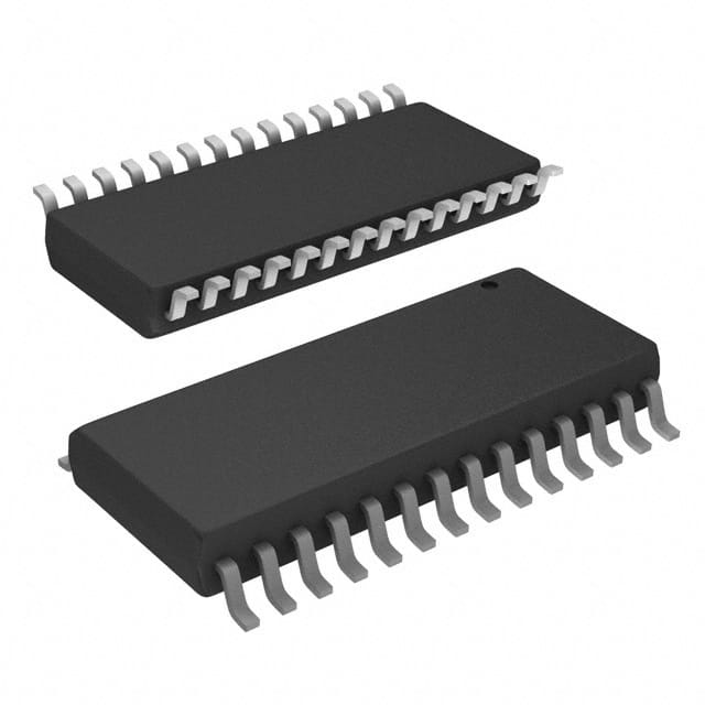
- Part No.:
- PCF1175CT/S420/2:1
- Manufacturer:
- NXP Semiconductors
- Category:
- Display Drivers
- Package:
- 28-SOIC (0.295", 7.50mm Width)
- Datasheet:
-
 PCF1175CT/S420/2:1.pdf
- Description:
- IC DRVR 7 SEGMENT 4 DIGIT 28SO
- Quantity:
- Payment:

- Shipping:

Inventory:2,884
Please send an inquiry. Send us your inquiry, and we will respond immediately.
Product details
Overview
PCF1175CT/S420/2:1 from Philips Semiconductors is a CMOS 4-digit duplex LCD car clock IC with integrated 4.19 MHz oscillator, electrically programmable voltage regulator (adjustable 3–6 V), and EEPROM-based time calibration. It drives automotive dashboard displays in 12- or 24-hour mode across −40 to +85 °C, supporting battery-powered operation via external resistor and 47 µF capacitor.
For engineers reviewing the PCF1175CT/S420/2:1 datasheet, PCF1175CT/S420/2:1 pinout, PCF1175CT/S420/2:1 application, or PCF1175CT/S420/2:1 equivalent, key selection considerations include its SO28 package, LCD segment/backplane drive architecture, temperature-compensated VDD regulation, EEPROM-programmable calibration, and dual-switch time-setting interface.
Technical Context
The PCF1175CT/S420/2:1 implements a 1:2 multiplexed duplex LCD driver with three-level backplane signals (BP1/BP2) generating VON(RMS) = 0.79 VDD and VOFF(RMS) = 0.35 VDD. Its internal 4.194304 MHz oscillator feeds a programmable divider chain for seconds/minutes/hours counting, with EEPROM-stored calibration pulses (0–31) to correct crystal frequency deviation up to +117.8 × 10⁻⁶.
Time setting uses two debounced SPST switch inputs (S1/S2) with auto-increment logic and enable control (ENABLE), while mode selection (12/24-hour) is determined by MODE pin level. LCD contrast is maintained via temperature-dependent VDD regulation-e.g., 4.5 V at 25 °C shifts to 3–4 V at +85 °C and 5–6 V at −40 °C.
Key Specifications
| Parameter | Value and Actual Design Meaning |
|---|---|
| Oscillator Frequency | 4.194304 MHz - fixed crystal reference enabling precise timekeeping without external timing components. |
| Operating Temperature | −40 to +85 °C - qualified for under-hood and dashboard automotive environments. |
| Supply Voltage Range | 3 to 6 V - supports wide battery voltage variation; regulated internally with temperature compensation. |
| Supply Current | 700–950 µA - ultra-low power consumption suitable for vehicle battery standby operation. |
| LCD Drive Architecture | 1:2 duplex multiplexing with BP1/BP2 backplanes - enables 4-digit display with reduced pin count and optimized contrast. |
| EEPROM Functions | Electrically programmable LCD voltage and time calibration - eliminates trimming capacitors and manual calibration. |
| Pin Count & Package | 28-pin SO28 (SOT136-1), 7.5 mm body width - surface-mount compatible with standard reflow/wave soldering processes. |
Pinout & Package
PCF1175CT/S420/2:1 is housed in a plastic small outline package (SO28, SOT136-1) with 28 leads, 7.5 mm body width, and 1.27 mm lead pitch. Pin 1 index is marked on the package per JEDEC MS-013AE.
| Pin/Terminal | Circuit Role | Design Meaning |
|---|---|---|
| S1 | Hour adjustment input | Debounced SPST switch input for hour increment; pull-up enabled; auto-increment on hold. |
| DATA | EEPROM data input | Serial programming interface for voltage and calibration settings; accepts pulse-width-encoded commands. |
| OSC IN / OSC OUT | Crystal oscillator terminals | Connects to 4.194304 MHz quartz; internal feedback resistor (300–3000 kΩ) eliminates external component. |
| VSS / VDD | Negative / positive supply | Ground and main supply pins; internal regulator derives LCD voltage from VDD via external resistor. |
| MODE | 12/24-hour mode select | Logic level determines time format: VDD = 12-hour, VSS = 24-hour, open = toggles on reset. |
| FLASH | Colon display control | VDD enables 1 Hz colon blinking; VSS holds colon static - direct visual mode indicator. |
| BP1 / BP2 | Three-level backplane outputs | Generate multiplexed AC waveforms for duplex LCD; define RMS segment voltages (0.79/0.35 × VDD). |
| A2/ADEG1 to F4/E4 | Segment drivers | 20 dedicated segment outputs mapped to 4-digit display including AM/PM, colon, and degree symbol. |
Key Features
| Feature | Design Value |
|---|---|
| Temperature-compensated LCD voltage regulation | Adjusts VDD output from 3–4 V at +85 °C to 5–6 V at −40 °C to maintain consistent LCD contrast across automotive thermal range. |
| EEPROM-based time calibration | Stores 0–31 correction pulses (each ~7.63 µs) to compensate crystal tolerance; eliminates manual trimmer capacitor. |
| Dual SPST switch time setting | Enables full time configuration (hours/minutes) using only two mechanical switches with built-in debounce and auto-increment. |
| 1 Hz colon blink control | Direct hardware control of colon visibility via FLASH pin - no firmware or timing logic required. |
| Low-power battery operation | Typical 950 µA supply current with 47 µF external capacitor enables multi-year operation from vehicle backup battery. |
Applications
| Automotive Dashboard Clock | Aftermarket Car Stereo Display |
|---|---|
|
Use Scenario: Integrated into OEM instrument clusters or center console modules requiring accurate, low-power timekeeping with LCD readout. IC Role / Device Role / Timing Role: Primary real-time clock generator and LCD segment/backplane driver with EEPROM-stored calibration and temperature-adaptive contrast. Use Value: Eliminates external crystal load capacitors, trimming components, and contrast-adjust potentiometers - reducing BOM cost and board space. |
Use Scenario: Embedded in third-party car audio head units where compact size and compatibility with existing 4-digit duplex LCD panels are critical. IC Role / Device Role / Timing Role: Standalone clock controller providing 12/24-hour mode, colon blink, and AM/PM indication without MCU intervention. Use Value: Enables rapid integration via simple switch inputs and fixed 28-pin SO28 footprint - avoids custom firmware development for basic time functions. |
| Commercial Vehicle Telematics Display | Industrial Fleet Management Terminal |
|
Use Scenario: Used in GPS-enabled truck dash displays needing reliable time stamping for log entries and event recording. IC Role / Device Role / Timing Role: Battery-backed RTC source synchronized to crystal reference; maintains time during ignition-off periods. Use Value: Internal voltage regulator sustains operation down to 3 V; EEPROM retains calibration across power cycles - ensuring long-term accuracy. |
Use Scenario: Deployed in ruggedized fleet terminals operating in extreme ambient temperatures (−40 to +85 °C). IC Role / Device Role / Timing Role: Automotive-qualified clock IC delivering stable segment drive and backplane timing despite thermal cycling. Use Value: Temperature-compensated VDD regulation ensures consistent LCD contrast without active thermal management or recalibration. |
Equivalent & Alternatives
The following parts are listed as comparable options for similar LCD car clock applications.
| Alternative Part | Technical Difference | Application Difference | Selection Advice |
|---|---|---|---|
| PCF1174CT | Same SO28 package and pinout; lacks EEPROM-based voltage regulation - requires external trimming capacitor for LCD bias. | Requires manual contrast adjustment; less suited for production environments demanding zero-calibration assembly. | Select when legacy design reuse is prioritized and contrast stability over temperature is managed externally. |
| PCF1176CT | Includes additional alarm function and buzzer driver; identical clock core and LCD drive architecture. | Supports audible time alerts; adds one extra output pin (ALARM) not present on PCF1175CT/S420/2:1. | Choose when alarm capability is needed without redesigning clock subsystem or changing display interface. |
Compared with PCF1175CT/S420/2:1, PCF1174CT trades EEPROM programmability for simpler analog biasing, while PCF1176CT extends functionality with alarm output - both retain identical timing accuracy, temperature range, and 4-digit duplex LCD drive capability.
Availability
PCF1175CT/S420/2:1 is available at Aetrix Electronics and suitable for automotive dashboard systems, aftermarket infotainment displays, and commercial vehicle telematics requiring stable component supply, long-lifecycle support, and guaranteed traceable sourcing.
Supply support for PCF1175CT/S420/2:1 includes scheduled delivery planning, volume procurement assistance, BOM continuity management, traceable sourcing, and lifecycle availability coordination for OEM customers, industrial embedded developers, connected-device designers, and electronics production programs.
Manufacturer
Philips Semiconductors (now NXP Semiconductors) is a global semiconductor innovator with leadership in automotive, consumer, and industrial ICs, emphasizing reliability, qualification rigor, and system-level integration.
The PCF1175CT/S420/2:1 belongs to Philips' car clock IC product line, designed specifically for cost-sensitive, high-volume automotive LCD time displays requiring zero-trim operation, wide temperature resilience, and minimal external components.
FAQ
What is the primary function of the PCF1175CT/S420/2:1 in automotive systems?
The PCF1175CT/S420/2:1 serves as a fully integrated 4-digit duplex LCD car clock IC, providing real-time hours/minutes/seconds counting, 12- or 24-hour mode selection, colon blink control, and direct segment/backplane drive. Its internal 4.194304 MHz oscillator, EEPROM-programmable calibration, and temperature-compensated voltage regulator eliminate external timing and contrast components - making PCF1175CT/S420/2:1 ideal for automotive dashboard and infotainment displays.
How does the PCF1175CT/S420/2:1 achieve temperature-stable LCD contrast?
The PCF1175CT/S420/2:1 achieves temperature-stable LCD contrast through an internal adjustable voltage regulator whose output varies with ambient temperature: e.g., programmed to 4.5 V at 25 °C, it delivers 3–4 V at +85 °C and 5–6 V at −40 °C. This automatic scaling maintains optimal RMS segment voltages (VON = 0.79 VDD, VOFF = 0.35 VDD) across the full −40 to +85 °C operating range - ensuring consistent contrast without user or system intervention in PCF1175CT/S420/2:1-based designs.
Can the PCF1175CT/S420/2:1 be used without an external crystal?
No - the PCF1175CT/S420/2:1 requires an external 4.194304 MHz quartz crystal connected between OSC IN and OSC OUT pins. The IC includes an internal feedback resistor (300–3000 kΩ) and oscillator circuitry but no built-in resonator; crystal load capacitance is set by internal design and does not require external capacitors. Omitting the crystal prevents oscillator startup and halts all timekeeping functions in the PCF1175CT/S420/2:1.
What are the time-setting interface requirements for the PCF1175CT/S420/2:1?
The PCF1175CT/S420/2:1 uses two SPST switch inputs (S1 for hours, S2 for minutes) with internal pull-up resistors (45–180 kΩ) and hardware debounce (30–100 ms). Time setting is enabled by connecting ENABLE to VDD; S1/S2 pulled to VSS initiate auto-increment (1 sec initial delay, then 1/sec). Both switches pressed simultaneously activates segment test mode. No microcontroller or external logic is needed - the complete time-setting interface for PCF1175CT/S420/2:1 consists of two switches, one enable line, and debounced inputs.
Is the PCF1175CT/S420/2:1 pin-compatible with other members of the PCF117x family?
Yes - the PCF1175CT/S420/2:1 shares identical SO28 (SOT136-1) packaging, pinout, and core functionality with PCF1174CT and PCF1176CT. Differences lie in feature set: PCF1174CT omits EEPROM voltage programming, while PCF1176CT adds ALARM output. All three support the same 4-digit duplex LCD drive, 4.19 MHz oscillator, and switch-based time setting - enabling drop-in substitution where feature alignment permits, as confirmed in Philips' official ordering information and package outline documentation for PCF1175CT/S420/2:1.
PCF1175CT/S420/2:1 Specifications
- Product attributes
- Attribute value
- Manufacturer:
- NXP Semiconductors
- Series:
- -
- Package/Case:
- 28-SOIC (0.295", 7.50mm Width)
- Packaging:
- Tape & Reel (TR)
- Product Status:
- Obsolete
- Display Type:
- LCD
- Configuration:
- 7 Segment
- Interface:
- -
- Digits or Characters:
- 4 Digits
- Current - Supply:
- 950 µA
- Voltage - Supply:
- 3V ~ 6V
- Operating Temperature:
- -40°C ~ 85°C
- Grade:
- -
- Qualification:
- -
- Mounting Type:
- Surface Mount
- Supplier Device Package:
- 28-SO
PCF1175CT/S420/2:1 FAQ
1.How can I place an order for PCF1175CT/S420/2:1 through Aetrix?
Please submit a Request for Quotation (RFQ) for PCF1175CT/S420/2:1 on Aetrix. Our sales agent will provide a competitive quotation and guide you through the order confirmation once you accept the terms.
2.Are the price and stock information for PCF1175CT/S420/2:1 reliable?
The price and inventory of PCF1175CT/S420/2:1 are updated periodically and may fluctuate due to market conditions. Stock and pricing data are typically refreshed every 24 hours. Quotation validity for PCF1175CT/S420/2:1 is usually 5 days.
3.What payment methods are accepted for PCF1175CT/S420/2:1?
We accept Wire Transfer, PayPal, Credit Card, Western Union, MoneyGram, and Escrow for PCF1175CT/S420/2:1 transactions.
Note: Certain payment methods may incur a processing fee.
4.How is shipping managed for PCF1175CT/S420/2:1?
PCF1175CT/S420/2:1 orders can be shipped via leading logistics carriers, including DHL, UPS, FedEx, TNT, or Registered Mail.
Once your PCF1175CT/S420/2:1 order is processed, you will receive an email with the shipment details and tracking number.
Note: Tracking information may take up to 24 hours to appear. Express delivery typically takes 3–5 business days.
5.How can I obtain technical support or documentation for PCF1175CT/S420/2:1?
For technical support, including PCF1175CT/S420/2:1 datasheets, pinout diagrams, or application guidance, please contact our engineering support team. They can provide detailed documentation and assistance for your PCF1175CT/S420/2:1 requirements.
6.How does Aetrix verify that PCF1175CT/S420/2:1 is sourced from the original manufacturer or authorized distributors?
All PCF1175CT/S420/2:1 products on Aetrix are procured from qualified distributors and authorized channels. Our dedicated quality assurance team conducts strict verification, including traceability checks and, if necessary, third-party testing. This ensures that PCF1175CT/S420/2:1 meets industry standards.
7.What is the process for return or replacement of PCF1175CT/S420/2:1?
All PCF1175CT/S420/2:1 units undergo pre-shipment inspection (PSI). If there is an issue with PCF1175CT/S420/2:1, returns or replacements are accepted under the following conditions:
1.Quantity discrepancies, incorrect items, or visible external defects (such as breakage or corrosion), acknowledged by Aetrix.
2.The issue is reported within 90 days of delivery.
3.The PCF1175CT/S420/2:1 part is unused and in its original packaging.
Return procedure for PCF1175CT/S420/2:1:
1.Submit a request within 90 days.
2.Obtain a Return Material Authorization (RMA) from Aetrix.
PCF1175CT/S420/2:1 Tags

-
PCA8561AHN/AY
NXP Semiconductors

-
SN74LS47N
Texas Instruments

-
PCF85176T/1Y
NXP Semiconductors
-
PCF85176H/1,518
NXP Semiconductors

-
BU9796AMUV-E2
Rohm Semiconductor
-
PCA85176H/Q900/1,5
NXP Semiconductors
-
PCF8537AH/1,518
NXP Semiconductors

-
LM3914VX/NOPB
Texas Instruments

-
PCF85134HL/1,118
NXP Semiconductors

-
AS1115-BSST
ams-OSRAM USA INC.
-
PCA8534AH/Q900/1,5
NXP Semiconductors
-
LM3914V/NOPB
Texas Instruments
Tech Hub

A practical engineering guide to 3.3V and 5V logic compatibility, input thresholds, resistor dividers, translator ICs, MOSFET level shifting, I2C pull-ups, timing limits and power-sequencing risks.

The 74HC595 uses push-pull logic outputs, while the TPIC6B595 uses 50 V open-drain DMOS sinks for higher-power loads. This guide compares timing, current limits, 3.3 V interfacing, load wiring, thermal…

The 74HC595 converts serial data into eight stable parallel outputs. This guide covers pin functions, shift and storage timing, OE and MR behavior, drive-current limits, cascading, voltage compatibilit…

A technical comparison of level-sensitive latches and edge-triggered flip-flops, covering timing windows, setup and hold limits, master–slave operation, time borrowing, race-through, HDL inference and…

A D latch stores one bit while Enable controls when data can pass. This reference covers gate-level operation, truth tables, transparency, setup and hold timing, LE versus OE, common ICs and practical …

An SR latch stores one bit through cross-coupled feedback. This engineering reference covers NOR and NAND implementations, truth tables, forbidden-state recovery, gated operation, switch debouncing, fa…

Latch circuits retain one bit through feedback. This technical reference covers SR and D latches, truth tables, transparency, timing limits, latch-versus-flip-flop behavior, applications and common log…

An engineering guide to LED driver operation, constant-current and constant-voltage outputs, linear and switching topologies, dimming, IC selection, calculations, replacement compatibility, and fault c…

Operational amplifier guide covering op amp basics, feedback, ideal vs real op amps, common configurations, buffer circuits, offset, bias current, gain-bandwidth, slew rate, rail-to-rail limits and sel…

Jumper cables guide covering safe connection order, red and black clamp placement, final ground connection, cable gauge, length, clamp quality, copper vs CCA cables, jump starter comparison and battery…


