
 My Inquiry
 My Account


NXP Semiconductors PCF2111CT/1,118
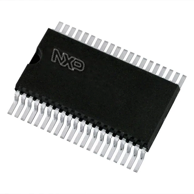
- Part No.:
- PCF2111CT/1,118
- Manufacturer:
- NXP Semiconductors
- Category:
- Display Drivers
- Package:
- 40-BSOP (0.295", 7.50mm Width)
- Datasheet:
-
 PCF2111CT/1,118.pdf
- Description:
- IC DRVR 64 SEGMENT 40VSOP
- Quantity:
- Payment:

- Shipping:

Inventory:3,351
Please send an inquiry. Send us your inquiry, and we will respond immediately.
Product details
Overview
PCF2111CT/1,118 from NXP Semiconductors is a single-chip CMOS LCD driver IC designed for 64-segment, 1:2 multiplexed LCD displays. It operates from 2.25 V to 6.0 V, consumes as low as 20 µA typical supply current at 25 °C, and features an integrated oscillator with C-bus serial interface for microcontroller connectivity - used in portable instrumentation and industrial panel meters.
For engineers reviewing the PCF2111CT/1,118 datasheet, PCF2111CT/1,118 pinout, PCF2111CT/1,118 application, or PCF2111CT/1,118 equivalent, key selection criteria include segment count (64), multiplex ratio (1:2), C-bus timing compliance (tCLB min 10 µs), oscillator start-up current (0.5–5.0 µA), and VSO40 package compatibility with fine-pitch PCB layouts.
Technical Context
The PCF2111CT/1,118 implements a 34-bit C-bus shift register with dual backplane latches (BP1/BP2) controlled by DATA bit 33 and CLB pulse 35. Its internal oscillator drives LCD bias generation without external components, supporting standalone operation or expansion via BP synchronization across multiple PCF21xxC devices.
Bus control logic performs real-time validation of leading zero, bit count, and signal integrity on DLEN/DATA lines - rejecting invalid frames and maintaining readiness for next valid load pulse. Output impedance is specified at 0.5–5.0 kΩ for BP pins and 1–7 kΩ for segment drivers under 5 V supply.
Key Specifications
| Parameter | Value and Actual Design Meaning |
|---|---|
| LCD Segments | 64 segments - supports alphanumeric or graphical 1:2 multiplexed displays up to 64 active elements |
| Multiplex Ratio | 1:2 - enables reduced component count and lower power vs. static drive; requires external resistive divider for VLCD |
| Supply Voltage | 2.25 V to 6.0 V - compatible with single-cell Li-ion, 3.3 V, and 5 V systems without level-shifting |
| Supply Current | 20 µA typical at 25 °C - enables battery life extension in portable metering applications |
| C-bus Timing | tCLB min 10 µs - defines minimum clock cycle for reliable 34-bit serial data transfer from MCU |
| Oscillator Start-up | 0.5–5.0 µA - ensures stable oscillation initiation across voltage and temperature range |
| Operating Temp | −40 °C to +85 °C - qualified for industrial environments including factory HMIs and outdoor instrumentation |
Pinout & Package
PCF2111CT/1,118 is housed in a plastic very small outline package (VSO40) with 40 leads and body width 5.4 mm (SOT158-1). Pin pitch is 0.5 mm, suitable for high-density SMT assembly using reflow soldering.
| Pin/Terminal | Circuit Role | Design Meaning |
|---|---|---|
| CLB (Pin 1) | C-bus clock burst input | Triggers latch loading after 34-bit shift register fill; tCLB ≥10 µs required for reliable frame transfer |
| VDD (Pin 2) | Positive supply rail | Power source for logic and driver stages; must be decoupled locally per layout guidelines |
| OSC (Pin 3) | Oscillator input | Connects to internal oscillator circuit; shorting to VSS enables master/slave expansion mode |
| VSS (Pin 4) | Ground reference | Common return for all analog/digital sections; must be low-impedance plane connection |
| S1–S32 (Pins 17–40) | Segment driver outputs | Drive LCD segments directly; each has 1–7 kΩ output impedance at 5 V for controlled waveform shaping |
| BP1 (Pin 37), BP2 (Pin 38) | Backplane driver outputs | Provide complementary AC bias for 1:2 multiplex; ZO = 0.5–5.0 kΩ enables precise duty-cycle control |
| DATA (Pin 39) | C-bus serial data input | Accepts 34-bit frame with bit 33 selecting BP1/BP2 latch; VIH ≥2.0 V, VIL ≤0.8 V |
| DLEN (Pin 40) | Data enable input | Active-low signal enabling C-bus frame capture; tSUEN ≥1 µs setup required before first CLB edge |
Key Features
| Feature | Design Value |
|---|---|
| Integrated oscillator | Eliminates external crystal/capacitor - reduces BOM count and board space in cost-sensitive metering designs |
| Power-on reset (POR) | Resets internal logic when VDD falls below 1.0–1.6 V - prevents undefined display states during brown-out |
| C-bus serial interface | 3-line bus (DLEN, DATA, CLB) minimizes MCU GPIO usage and simplifies firmware integration vs. parallel interfaces |
| Expansion capability | BP synchronization allows cascading multiple PCF2111CT/1,118 units to drive >64 segments without additional controllers |
| Low-power operation | 20 µA typical IDD at 25 °C enables multi-year battery life in portable handheld instruments |
Applications
| Portable Multimeters | Industrial Panel Meters |
|---|---|
Use Scenario: Handheld digital multimeter with 4-digit LCD and bar-graph display. IC Role / Device Role / Timing Role: Primary LCD driver managing 64 segments across main digits and auxiliary indicators using 1:2 multiplexing. Use Value: Low 20 µA supply current extends alkaline battery life beyond 1,000 hours; integrated oscillator removes timing component dependency. | Use Scenario: DIN-rail mounted process monitor displaying pressure, temperature, and flow parameters. IC Role / Device Role / Timing Role: Standalone LCD controller interfacing to 8-bit MCU via C-bus, driving segmented display with backlight control. Use Value: −40 °C to +85 °C rating ensures reliability in unconditioned industrial cabinets; VSO40 package supports automated SMT assembly. |
| Gas Detector Displays | Medical Patient Monitors |
Use Scenario: Battery-powered portable gas detector with hazard warning icons and concentration readout. IC Role / Device Role / Timing Role: Segment driver handling 64-element display including alarm symbols and numeric fields under strict power budget. Use Value: 2.25 V minimum VDD enables operation down to near-dead battery; POR prevents ghosting during wake-up transitions. | Use Scenario: Bedside vital signs monitor with segmented display for SpO₂, pulse rate, and battery status. IC Role / Device Role / Timing Role: Secondary display driver synchronized to main controller, updating critical parameters every 200 ms. Use Value: C-bus timing compliance (tCLB ≥10 µs) ensures deterministic update latency; ESD rating ±2000 V HBM protects against clinical environment discharge events. |
Equivalent & Alternatives
The following parts are listed as comparable options for similar LCD driver applications.
| Alternative Part | Technical Difference | Application Difference | Selection Advice |
|---|---|---|---|
| PCF2112CT/1,118 | 32-segment capacity, 1:1 multiplex, 34-bit word length, same VSO40 package | Targeted at simpler displays (e.g., basic timers); lacks BP2 output and expansion flexibility | Select when segment count ≤32 and static drive suffices; not interchangeable due to different pin mapping and timing |
| PCF2100CT/1,112 | 40-segment capacity, 1:2 multiplex, 22-bit word length, SO28 package (SOT136-1) | Requires larger PCB footprint; lower segment density limits display complexity | Choose for legacy SO28 layouts or where 40 segments meet UI requirements; incompatible pinout prevents drop-in replacement |
Compared with PCF2111CT/1,118, PCF2112CT/1,118 offers half the segment count but identical package and bus interface, while PCF2100CT/1,112 uses a different package and supports fewer segments - both require PCB redesign and firmware adaptation.
Availability
PCF2111CT/1,118 is available at Aetrix Electronics and suitable for portable instrumentation, industrial panel meters, and gas detection systems requiring stable component supply across extended product lifecycles.
Supply support for PCF2111CT/1,118 includes scheduled delivery planning, volume procurement assistance, BOM continuity management, traceable sourcing, and lifecycle availability coordination for OEM customers, industrial embedded developers, connected-device designers, and electronics production programs.
Manufacturer
NXP Semiconductors is a global semiconductor company specializing in secure connectivity solutions for automotive, industrial, and IoT applications.
The PCF21xxC family was developed specifically for low-power, microcontroller-connected LCD display systems in portable and industrial equipment - emphasizing integration, reliability, and ease of system-level timing design.
FAQ
What is the maximum LCD display frequency supported by the PCF2111CT/1,118?
The PCF2111CT/1,118 supports a maximum LCD display frequency of 100 Hz under typical conditions (VDD = 5 V, CO = 680 pF). This value scales with supply voltage and load capacitance - dropping to 60 Hz minimum at VDD = 2.25 V. The internal oscillator sets this frequency, and no external timing components are required for basic operation of the PCF2111CT/1,118.
Does the PCF2111CT/1,118 require external components for oscillator operation?
No, the PCF2111CT/1,118 includes a built-in one-point oscillator that operates without external crystals or capacitors. When OSC is left unconnected or tied to VSS, the internal oscillator runs autonomously. External components are only needed if custom frequency tuning or master-slave expansion is implemented - the base functionality of the PCF2111CT/1,118 is fully self-contained.
How many LCD segments can the PCF2111CT/1,118 drive, and what multiplex ratio does it use?
The PCF2111CT/1,118 drives exactly 64 LCD segments using a 1:2 multiplex ratio. This configuration requires two backplane outputs (BP1 and BP2), which are provided on pins 37 and 38. The 1:2 ratio halves the number of required interconnects versus static drive and reduces average segment current - a key advantage for battery-powered applications using the PCF2111CT/1,118.
What package type is used for the PCF2111CT/1,118, and what are its key mechanical features?
The PCF2111CT/1,118 uses the VSO40 package (SOT158-1): a plastic very small outline package with 40 leads, 0.5 mm pitch, and 5.4 mm body width. It is designed for surface-mount reflow assembly and complies with moisture sensitivity level (MSL) requirements for standard handling. The compact footprint supports high-density PCB layouts essential for portable devices using the PCF2111CT/1,118.
Can multiple PCF2111CT/1,118 devices be synchronized for larger displays?
Yes, the PCF2111CT/1,118 supports expansion via BP synchronization: connecting the OSC pin of slave units to the BP1/BP2 outputs of a master unit aligns their display timing. This allows cascading multiple PCF2111CT/1,118 ICs to drive displays exceeding 64 segments while maintaining coherent flicker-free operation - a capability confirmed in the functional description section of the PCF2111CT/1,118 datasheet.
PCF2111CT/1,118 Specifications
- Product attributes
- Attribute value
- Manufacturer:
- NXP Semiconductors
- Series:
- -
- Package/Case:
- 40-BSOP (0.295", 7.50mm Width)
- Packaging:
- Tape & Reel (TR)
- Product Status:
- Obsolete
- Display Type:
- LCD
- Configuration:
- 64 Segment
- Interface:
- Serial
- Digits or Characters:
- -
- Current - Supply:
- 20 µA
- Voltage - Supply:
- 2.25V ~ 6V
- Operating Temperature:
- -40°C ~ 85°C
- Grade:
- -
- Qualification:
- -
- Mounting Type:
- Surface Mount
- Supplier Device Package:
- 40-VSO
PCF2111CT/1,118 FAQ
1.How can I place an order for PCF2111CT/1,118 through Aetrix?
Please submit a Request for Quotation (RFQ) for PCF2111CT/1,118 on Aetrix. Our sales agent will provide a competitive quotation and guide you through the order confirmation once you accept the terms.
2.Are the price and stock information for PCF2111CT/1,118 reliable?
The price and inventory of PCF2111CT/1,118 are updated periodically and may fluctuate due to market conditions. Stock and pricing data are typically refreshed every 24 hours. Quotation validity for PCF2111CT/1,118 is usually 5 days.
3.What payment methods are accepted for PCF2111CT/1,118?
We accept Wire Transfer, PayPal, Credit Card, Western Union, MoneyGram, and Escrow for PCF2111CT/1,118 transactions.
Note: Certain payment methods may incur a processing fee.
4.How is shipping managed for PCF2111CT/1,118?
PCF2111CT/1,118 orders can be shipped via leading logistics carriers, including DHL, UPS, FedEx, TNT, or Registered Mail.
Once your PCF2111CT/1,118 order is processed, you will receive an email with the shipment details and tracking number.
Note: Tracking information may take up to 24 hours to appear. Express delivery typically takes 3–5 business days.
5.How can I obtain technical support or documentation for PCF2111CT/1,118?
For technical support, including PCF2111CT/1,118 datasheets, pinout diagrams, or application guidance, please contact our engineering support team. They can provide detailed documentation and assistance for your PCF2111CT/1,118 requirements.
6.How does Aetrix verify that PCF2111CT/1,118 is sourced from the original manufacturer or authorized distributors?
All PCF2111CT/1,118 products on Aetrix are procured from qualified distributors and authorized channels. Our dedicated quality assurance team conducts strict verification, including traceability checks and, if necessary, third-party testing. This ensures that PCF2111CT/1,118 meets industry standards.
7.What is the process for return or replacement of PCF2111CT/1,118?
All PCF2111CT/1,118 units undergo pre-shipment inspection (PSI). If there is an issue with PCF2111CT/1,118, returns or replacements are accepted under the following conditions:
1.Quantity discrepancies, incorrect items, or visible external defects (such as breakage or corrosion), acknowledged by Aetrix.
2.The issue is reported within 90 days of delivery.
3.The PCF2111CT/1,118 part is unused and in its original packaging.
Return procedure for PCF2111CT/1,118:
1.Submit a request within 90 days.
2.Obtain a Return Material Authorization (RMA) from Aetrix.
PCF2111CT/1,118 Tags

-
PCA8561AHN/AY
NXP Semiconductors

-
SN74LS47N
Texas Instruments

-
PCF85176T/1Y
NXP Semiconductors
-
PCF85176H/1,518
NXP Semiconductors

-
BU9796AMUV-E2
Rohm Semiconductor
-
PCA85176H/Q900/1,5
NXP Semiconductors
-
PCF8537AH/1,518
NXP Semiconductors

-
LM3914VX/NOPB
Texas Instruments

-
PCF85134HL/1,118
NXP Semiconductors

-
AS1115-BSST
ams-OSRAM USA INC.
-
PCA8534AH/Q900/1,5
NXP Semiconductors
-
LM3914V/NOPB
Texas Instruments
Tech Hub

A practical engineering guide to 3.3V and 5V logic compatibility, input thresholds, resistor dividers, translator ICs, MOSFET level shifting, I2C pull-ups, timing limits and power-sequencing risks.

The 74HC595 uses push-pull logic outputs, while the TPIC6B595 uses 50 V open-drain DMOS sinks for higher-power loads. This guide compares timing, current limits, 3.3 V interfacing, load wiring, thermal…

The 74HC595 converts serial data into eight stable parallel outputs. This guide covers pin functions, shift and storage timing, OE and MR behavior, drive-current limits, cascading, voltage compatibilit…

A technical comparison of level-sensitive latches and edge-triggered flip-flops, covering timing windows, setup and hold limits, master–slave operation, time borrowing, race-through, HDL inference and…

A D latch stores one bit while Enable controls when data can pass. This reference covers gate-level operation, truth tables, transparency, setup and hold timing, LE versus OE, common ICs and practical …

An SR latch stores one bit through cross-coupled feedback. This engineering reference covers NOR and NAND implementations, truth tables, forbidden-state recovery, gated operation, switch debouncing, fa…

Latch circuits retain one bit through feedback. This technical reference covers SR and D latches, truth tables, transparency, timing limits, latch-versus-flip-flop behavior, applications and common log…

An engineering guide to LED driver operation, constant-current and constant-voltage outputs, linear and switching topologies, dimming, IC selection, calculations, replacement compatibility, and fault c…

Operational amplifier guide covering op amp basics, feedback, ideal vs real op amps, common configurations, buffer circuits, offset, bias current, gain-bandwidth, slew rate, rail-to-rail limits and sel…

Jumper cables guide covering safe connection order, red and black clamp placement, final ground connection, cable gauge, length, clamp quality, copper vs CCA cables, jump starter comparison and battery…


