
 My Inquiry
 My Account


NXP Semiconductors PCF8583BS,518
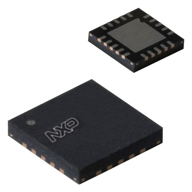
- Part No.:
- PCF8583BS,518
- Manufacturer:
- NXP Semiconductors
- Category:
- Real Time Clocks
- Package:
- 20-VQFN Exposed Pad
- Datasheet:
-
 PCF8583BS,518.pdf
- Description:
- IC RTC CLK/CALENDAR I2C 20HVQFN
- Quantity:
- Payment:

- Shipping:

Inventory:2,618
Please send an inquiry. Send us your inquiry, and we will respond immediately.
Product details
Overview
PCF8583BS,518 from NXP Semiconductors is a serial real-time clock and calendar IC with 240 × 8-bit low-voltage RAM, I²C-bus interface (2.5–6.0 V), integrated 32.768 kHz oscillator circuit, and programmable alarm/timer functions. It supports 24/12-hour format, four-year calendar, and event counting up to 1 million pulses - deployed in industrial control panels and embedded metering systems requiring battery-backed timekeeping.
For engineers reviewing the PCF8583BS,518 datasheet, PCF8583BS,518 pinout, PCF8583BS,518 application, or PCF8583BS,518 equivalent, key selection criteria include its HVQFN20 package compatibility, dual I²C slave addresses (A0h/A2h write, A1h/A3h read), 1.0 V data retention capability, interrupt-driven alarm signaling, and BCD-encoded counter registers for direct calendar readout without software conversion.
Technical Context
The PCF8583BS,518 implements a dedicated clock/calendar subsystem using an on-chip 32.768 kHz oscillator driving a frequency divider to generate 1 Hz and sub-second timing signals. Its 256 × 8-bit RAM includes 8 bytes for clock counters (00h–07h), 8 bytes for alarm/timer control (08h–0Fh), and 240 bytes of general-purpose RAM - all accessed via auto-incrementing I²C address register.
It operates in three functional modes: 32.768 kHz clock mode (default), 50 Hz reference input mode, and external event-counter mode. Alarm logic compares BCD values across date/time registers with maskable bits (e.g., year/weekday ignored in daily alarms), while the open-drain INT pin asserts active-low on alarm flag, timer overflow, or event match - all software-resettable via control/status register (00h).
Key Specifications
| Parameter | Value and Actual Design Meaning |
|---|---|
| I²C Supply Voltage | 2.5 V to 6.0 V - enables direct interfacing with 3.3 V or 5 V microcontrollers without level-shifting. |
| Clock Supply Voltage | 1.0 V to 6.0 V at 0 °C to +70 °C - supports battery backup down to 1.0 V for continuous timekeeping during main power loss. |
| RAM Capacity | 240 × 8-bit - provides nonvolatile storage space for application data, configuration, or logging alongside timekeeping registers. |
| Operating Current | Max 50 μA at fSCL = 0 Hz - ensures ultra-low power consumption in sleep or standby states for extended battery life. |
| Time Base Options | 32.768 kHz crystal or 50 Hz AC line - allows flexible time source selection for precision or cost-sensitive applications. |
| Alarm Types | Dated, daily, weekday, and timer alarms - enables scheduling of maintenance alerts, energy tariff switching, or periodic system wake-up. |
| Interrupt Output | Open-drain INT pin - simplifies connection to microcontroller GPIO with external pull-up; supports 1 Hz calibration toggle when alarm disabled. |
Pinout & Package
HVQFN20 package (SOT662-1), 5 × 5 × 0.85 mm body, thermally enhanced, no leads, exposed die paddle connected to VSS.
| Pin/Terminal | Circuit Role | Design Meaning |
|---|---|---|
| OSCI | Oscillator input | Accepts 32.768 kHz crystal or 50 Hz external signal; high-impedance in event-counter mode. |
| OSCO | Oscillator output | Drives crystal; left open-circuit in event-counter mode to enable external pulse counting on OSCI. |
| A0 | Hardware address input | Configures I²C slave address: A0 = LOW → write address A0h/read A1h; A0 = HIGH → write A2h/read A3h. |
| VSS | Ground supply | Reference for all signals; die paddle must be electrically isolated and tied to VSS per mechanical spec. |
| SDA | Serial data line | Bi-directional I²C data pin; requires external pull-up resistor; supports standard-mode (100 kHz) communication. |
| SCL | Serial clock line | Input-only I²C clock; synchronizes data transfer; driven by master controller. |
| INT | Interrupt output | Open-drain, active-low signal indicating alarm, timer overflow, or event match; requires external pull-up. |
| VDD | Supply voltage | Power rail for I²C interface and RAM; supports 2.5–6.0 V operation; decoupling capacitor recommended near pin. |
| n.c. | No connect | 12 terminals (pins 1, 6–11, 16–20) are unconnected; must remain floating and not used as vias or traces. |
Key Features
| Feature | Design Value |
|---|---|
| Auto-incrementing I²C address register | Eliminates manual address management during sequential read/write of time registers (00h–07h), reducing firmware overhead. |
| BCD-encoded time registers | Enables direct human-readable time/date access (e.g., 0x23 for 23 seconds) without binary-to-BCD conversion in host MCU. |
| Programmable alarm masking | Control/status register bit 3 allows masked reads of date/month (05h/06h) to avoid carry-related corruption during updates. |
| Event counter with 6-digit capacity | Counts up to 999,999 pulses on OSCI in event mode; stores values in BCD across registers 01h–03h for easy parsing. |
| 1 Hz calibration output | When alarm disabled, INT toggles at precise 1 Hz with 50% duty cycle - usable for system clock calibration or LED blink timing. |
Applications
| Industrial Control Panel | Smart Energy Meter |
|---|---|
Use Scenario: Time-stamping of process events and operator actions in PLC-based HMI systems. IC Role / Device Role / Timing Role: Primary real-time clock and calendar with battery-backed RAM for persistent timestamp storage. Use Value: Ensures traceability of operational logs across power cycles using 1.0 V data retention and BCD register structure. |
Use Scenario: Recording kWh consumption with tariff period switching (peak/off-peak) based on local time. IC Role / Device Role / Timing Role: Calendar-aware scheduler triggering relay control and data upload at defined intervals. Use Value: Enables accurate billing via four-year calendar and programmable daily alarms synchronized to utility rate schedules. |
| Embedded HVAC Controller | Medical Device Log Module |
Use Scenario: Scheduling fan speed changes, filter alerts, and temperature setpoint adjustments over weekly cycles. IC Role / Device Role / Timing Role: Weekday- and date-aware alarm generator driving system-level state transitions. Use Value: Supports complex recurring schedules (e.g., "every Monday at 08:00") using weekday mask register (0Eh) and BCD time matching. |
Use Scenario: Timestamping diagnostic events and sensor readings in portable patient monitors with battery backup. IC Role / Device Role / Timing Role: Low-power RTC maintaining accurate time during standby using 50 μA max operating current. Use Value: Guarantees regulatory-compliant audit trails with tamper-resistant time stamps stored in on-chip RAM. |
Equivalent & Alternatives
The following parts are listed as comparable options for similar real-time clock and calendar applications.
| Alternative Part | Technical Difference | Application Difference | Selection Advice |
|---|---|---|---|
| DS1307+T&R | Lacks event counter; uses external crystal load capacitors; no 50 Hz input mode; 128 × 8-bit RAM. | Not suitable for pulse-counting applications; limited alarm flexibility (no weekday/dated alarms). | Select DS1307+T&R only if basic RTC functionality suffices and board layout lacks space for trimmer capacitor. |
| PCF8563T | Successor IC with identical HVQFN20 package; lower typical current (0.25 μA); added century bit; improved oscillator stability. | Direct drop-in replacement where extended battery life and enhanced calendar accuracy are required. | Choose PCF8563T for new designs needing longer backup duration and backward-compatible register mapping. |
Compared with DS1307+T&R, PCF8583BS,518 offers superior alarm granularity and event counting; versus PCF8563T, it trades lower power for broader legacy support and simpler initialization - making it optimal for cost-sensitive industrial retrofits requiring dated alarms and 50 Hz line synchronization.
Availability
PCF8583BS,518 is available at Aetrix Electronics and suitable for industrial control panels, smart energy meters, embedded HVAC controllers, and medical device log modules requiring stable component supply across extended product lifecycles.
Supply support for PCF8583BS,518 includes scheduled delivery planning, volume procurement assistance, BOM continuity management, traceable sourcing, and lifecycle availability coordination for OEM customers, industrial embedded developers, connected-device designers, and electronics production programs.
Manufacturer
NXP Semiconductors is a global semiconductor company headquartered in Eindhoven, Netherlands, specializing in secure connectivity solutions for automotive, industrial, and IoT applications.
The PCF8583BS,518 belongs to NXP's legacy real-time clock family designed for robust, low-power timekeeping in resource-constrained embedded systems - emphasizing long-term reliability, wide voltage operation, and I²C simplicity over advanced features like temperature compensation.
FAQ
What is the primary function of the PCF8583BS,518?
The PCF8583BS,518 is a dedicated real-time clock and calendar IC with integrated 240 × 8-bit RAM, I²C interface, and programmable alarm/timer functions. It maintains accurate time and date using a 32.768 kHz crystal or 50 Hz input, stores timestamps and application data, and generates interrupt-driven alerts - all within the PCF8583BS,518's HVQFN20 package.
Does the PCF8583BS,518 support battery backup operation?
Yes, the PCF8583BS,518 supports data retention down to 1.0 V supply voltage, enabling continuous timekeeping during main power loss when backed by a coin cell or supercapacitor. Its low operating current (max 50 μA at 0 Hz) extends backup runtime, and the internal oscillator remains functional across the 1.0–6.0 V range specified for clock operation at 0 °C to +70 °C.
How does the PCF8583BS,518 handle alarm conditions?
The PCF8583BS,518 supports dated, daily, weekday, and timer alarms via BCD-matching logic against registers 01h–07h. When triggered, it sets the alarm flag (bit 1 of control/status register 00h) and drives the open-drain INT pin low. The flag persists until cleared by software write, and alarm registers 08h–0Fh become free RAM when alarm is disabled - a behavior confirmed in the PCF8583BS,518 datasheet Section 7.2.
Can the PCF8583BS,518 operate without an external crystal?
Yes, the PCF8583BS,518 can operate in 50 Hz clock mode or event-counter mode with the oscillator disabled. In these modes, OSCI accepts an external 50 Hz AC signal or pulse train, while OSCO is left open-circuit. This eliminates the need for a crystal and associated load capacitors - a verified capability documented in PCF8583BS,518 Section 7.10 and Table 4.
What are the I²C slave addresses for the PCF8583BS,518?
The PCF8583BS,518 uses hardware-addressable I²C slave addresses determined by the A0 pin: A0 = LOW yields write address 0xA0 and read address 0xA1; A0 = HIGH yields write address 0xA2 and read address 0xA3. These fixed 7-bit addresses (with R/W bit appended) are defined in Table 5 of the PCF8583BS,518 datasheet and allow two devices on the same bus without additional logic.
PCF8583BS,518 Specifications
- Product attributes
- Attribute value
- Manufacturer:
- NXP Semiconductors
- Series:
- -
- Package/Case:
- 20-VQFN Exposed Pad
- Packaging:
- Tape & Reel (TR)
- Product Status:
- Obsolete
- Programmable:
- Not Verified
- Type:
- Clock/Calendar
- Features:
- Alarm, NVSRAM, Square Wave Output
- Memory Size:
- 240B
- Time Format:
- HH:MM:SS:hh (12/24 hr)
- Date Format:
- YY-MM-DD
- Interface:
- I2C, 2-Wire Serial
- Voltage - Supply:
- 2.5V ~ 6V
- Voltage - Supply, Battery:
- -
- Current - Timekeeping (Max):
- 10µA ~ 50µA @ 1V ~ 5V
- Operating Temperature:
- -40°C ~ 85°C
- Mounting Type:
- Surface Mount
- Grade:
- -
- Qualification:
- -
- Supplier Device Package:
- 20-HVQFN (5x5)
PCF8583BS,518 FAQ
1.How can I place an order for PCF8583BS,518 through Aetrix?
Please submit a Request for Quotation (RFQ) for PCF8583BS,518 on Aetrix. Our sales agent will provide a competitive quotation and guide you through the order confirmation once you accept the terms.
2.Are the price and stock information for PCF8583BS,518 reliable?
The price and inventory of PCF8583BS,518 are updated periodically and may fluctuate due to market conditions. Stock and pricing data are typically refreshed every 24 hours. Quotation validity for PCF8583BS,518 is usually 5 days.
3.What payment methods are accepted for PCF8583BS,518?
We accept Wire Transfer, PayPal, Credit Card, Western Union, MoneyGram, and Escrow for PCF8583BS,518 transactions.
Note: Certain payment methods may incur a processing fee.
4.How is shipping managed for PCF8583BS,518?
PCF8583BS,518 orders can be shipped via leading logistics carriers, including DHL, UPS, FedEx, TNT, or Registered Mail.
Once your PCF8583BS,518 order is processed, you will receive an email with the shipment details and tracking number.
Note: Tracking information may take up to 24 hours to appear. Express delivery typically takes 3–5 business days.
5.How can I obtain technical support or documentation for PCF8583BS,518?
For technical support, including PCF8583BS,518 datasheets, pinout diagrams, or application guidance, please contact our engineering support team. They can provide detailed documentation and assistance for your PCF8583BS,518 requirements.
6.How does Aetrix verify that PCF8583BS,518 is sourced from the original manufacturer or authorized distributors?
All PCF8583BS,518 products on Aetrix are procured from qualified distributors and authorized channels. Our dedicated quality assurance team conducts strict verification, including traceability checks and, if necessary, third-party testing. This ensures that PCF8583BS,518 meets industry standards.
7.What is the process for return or replacement of PCF8583BS,518?
All PCF8583BS,518 units undergo pre-shipment inspection (PSI). If there is an issue with PCF8583BS,518, returns or replacements are accepted under the following conditions:
1.Quantity discrepancies, incorrect items, or visible external defects (such as breakage or corrosion), acknowledged by Aetrix.
2.The issue is reported within 90 days of delivery.
3.The PCF8583BS,518 part is unused and in its original packaging.
Return procedure for PCF8583BS,518:
1.Submit a request within 90 days.
2.Obtain a Return Material Authorization (RMA) from Aetrix.
PCF8583BS,518 Tags

-
MCP7940N-I/SN
Microchip Technology

-
MCP7940MT-I/MNY
Microchip Technology

-
PCF85063ATL/1,118
NXP USA Inc.
-
MCP7940NT-I/SN
Microchip Technology

-
MCP7940NT-I/MS
Microchip Technology
-
MCP7940N-I/MS
Microchip Technology

-
PCF85063AT/AY
NXP USA Inc.

-
PCF85063TP/1Z
NXP Semiconductors

-
PCF85063ATT/AJ
NXP USA Inc.
-
MCP7940NT-E/SN
Microchip Technology
-
MCP7940NT-I/MNY
Microchip Technology
-
MCP79400T-I/SN
Microchip Technology
Tech Hub

A practical engineering guide to 3.3V and 5V logic compatibility, input thresholds, resistor dividers, translator ICs, MOSFET level shifting, I2C pull-ups, timing limits and power-sequencing risks.

The 74HC595 uses push-pull logic outputs, while the TPIC6B595 uses 50 V open-drain DMOS sinks for higher-power loads. This guide compares timing, current limits, 3.3 V interfacing, load wiring, thermal…

The 74HC595 converts serial data into eight stable parallel outputs. This guide covers pin functions, shift and storage timing, OE and MR behavior, drive-current limits, cascading, voltage compatibilit…

A technical comparison of level-sensitive latches and edge-triggered flip-flops, covering timing windows, setup and hold limits, master–slave operation, time borrowing, race-through, HDL inference and…

A D latch stores one bit while Enable controls when data can pass. This reference covers gate-level operation, truth tables, transparency, setup and hold timing, LE versus OE, common ICs and practical …

An SR latch stores one bit through cross-coupled feedback. This engineering reference covers NOR and NAND implementations, truth tables, forbidden-state recovery, gated operation, switch debouncing, fa…

Latch circuits retain one bit through feedback. This technical reference covers SR and D latches, truth tables, transparency, timing limits, latch-versus-flip-flop behavior, applications and common log…

An engineering guide to LED driver operation, constant-current and constant-voltage outputs, linear and switching topologies, dimming, IC selection, calculations, replacement compatibility, and fault c…

Operational amplifier guide covering op amp basics, feedback, ideal vs real op amps, common configurations, buffer circuits, offset, bias current, gain-bandwidth, slew rate, rail-to-rail limits and sel…

Jumper cables guide covering safe connection order, red and black clamp placement, final ground connection, cable gauge, length, clamp quality, copper vs CCA cables, jump starter comparison and battery…


