
 My Inquiry
 My Account


Diodes Incorporated PI3L500-AZFEX
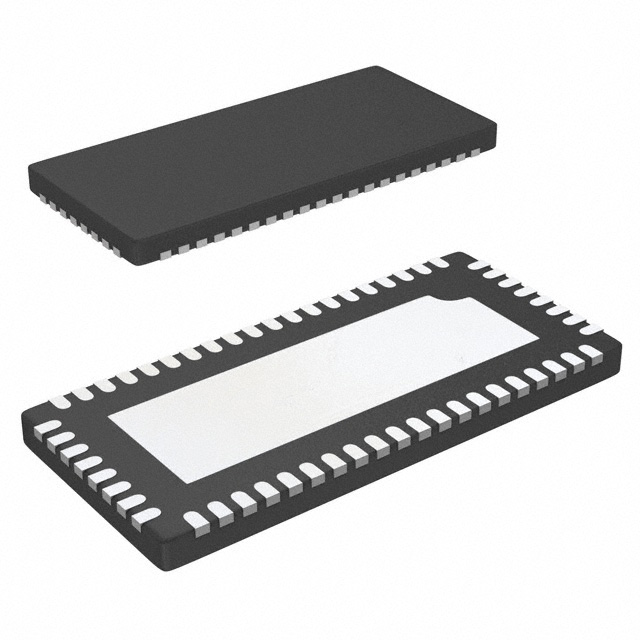
- Part No.:
- PI3L500-AZFEX
- Manufacturer:
- Diodes Incorporated
- Category:
- Analog Switches - Special Purpose
- Package:
- 56-WFQFN Exposed Pad
- Datasheet:
-
 PI3L500-AZFEX.pdf
- Description:
- IC MUX/DEMUX 8 X 2:1 56TQFN
- Quantity:
- Payment:

- Shipping:

Inventory:3,814
Please send an inquiry. Send us your inquiry, and we will respond immediately.
Product details
Overview
PI3L500-AZFEX from Diodes Incorporated (acquired Pericom) is an 8-channel, 2:1 bidirectional analog multiplexer/demultiplexer LAN switch optimized for Gigabit Ethernet (1000BASE-T) signal routing. It features 4Ω typical on-resistance, <250ps propagation delay, –35dB crosstalk at 250MHz, and Hi-Z outputs-enabling low-distortion differential pair switching between two PHY interfaces over CAT5/CAT6 UTP via isolation transformers.
For engineers reviewing the PI3L500-AZFEX datasheet, PI3L500-AZFEX pinout, PI3L500-AZFEX application in Ethernet PHY sharing, or PI3L500-AZFEX equivalent for 10/100/1000BASE-T LAN switching, this page delivers verified electrical specs, validated pin mapping, real-world use cases, and technically grounded alternative options with documented functional differences.
Technical Context
The PI3L500-AZFEX implements a CMOS-based analog switch architecture with rail-to-rail logic-compatible control inputs (VIH = 2.0V min, VIL = 0.8V max) and operates exclusively from a 3.3V ±10% supply. Its internal topology supports simultaneous switching of eight differential pairs (A0–A7 to B1/B2 ports), with SEL pin controlling path selection (AX→XB1 or AX→XB2) and independent LED driver outputs (LED0–LED2, XLED1/XLED2) synchronized to channel activity.
Designed for high-fidelity Ethernet signal integrity, it achieves >350MHz bandwidth (–3dB), <200ps bit-to-bit skew, and maintains <0.5Ω on-resistance flatness across all channels-ensuring matched impedance and minimal timing mismatch in full-duplex 1000BASE-T applications where differential skew directly impacts receiver eye margin.
Key Specifications
| Parameter | Value and Actual Design Meaning |
|---|---|
| RON (typ) | 4 Ω - Enables <1% voltage drop at 100mA per channel, preserving signal amplitude integrity in 100Ω differential Ethernet paths. |
| tPD (typ) | 0.25 ns - Near-zero added delay ensures end-to-end PHY-to-PHY latency remains dominated by transformer and cable propagation, not switch insertion. |
| XTALK @ 250MHz | –35 dB - Suppresses inter-pair coupling sufficiently to meet 1000BASE-T NEXT requirements without additional board-level shielding. |
| Bandwidth (–3dB) | 350 MHz - Supports clean transmission of 125MHz fundamental + harmonics required for 1000BASE-T PAM-5 signaling. |
| VCC Range | +3.0V to +3.6V - Matches standard 3.3V Ethernet PHY supply rails and tolerates typical DC-DC ripple without regulation overhead. |
| ESD Protection | ±8kV contact (IEC 61000-4-2), 12kV HBM on switch pins - Eliminates need for external TVS diodes on Ethernet data lanes in industrial port designs. |
| Channel Count | 8 independent 2:1 mux/demux channels - Routes all four differential pairs (TX+/−, RX+/− ×2) of dual 1000BASE-T PHYs to shared RJ45 magnetics. |
Pinout & Package
PI3L500-AZFEX is housed in a Pb-free, green 56-contact TQFN package (code ZF), 7.0mm × 7.0mm × 0.8mm, with exposed thermal pad (EP) connected to GND for enhanced power dissipation in sustained switching operation.
| Pin/Terminal | Circuit Role | Design Meaning |
|---|---|---|
| A0–A7 | Differential input pairs (DeMux side) | Accept 100Ω differential signals from primary/secondary Ethernet PHY transceivers; AC-coupled via magnetics. |
| 0B1–7B1, 0B2–7B2 | Differential output pairs (Mux side) | Drive corresponding B1 (path 1) or B2 (path 2) RJ45 magnetics; Hi-Z when unselected preserves signal termination. |
| SEL | Global 2:1 path select control | Active-High logic input determining whether A0–A7 route to B1 or B2 banks; no internal pull-up/down. |
| LED0–LED2, XLED1/XLED2 | LED driver outputs | Open-drain drivers sinking current to illuminate status LEDs synchronized with active channel selection and direction. |
| VCC, GND (×10 pins) | Power and ground distribution | Multiple VCC/GND pins minimize IR drop and ground bounce across high-speed analog signal paths. |
Key Features
| Feature | Design Value |
|---|---|
| Sub-250ps propagation delay | Reduces cumulative PHY-to-PHY latency to <1ns, critical for time-sensitive industrial Ethernet protocols like PROFINET IRT. |
| 0.4Ω ΔRON matching | Ensures <5ps skew between any two channels, maintaining 1000BASE-T symbol alignment across all four twisted pairs. |
| Integrated LED drivers | Eliminates 8 discrete transistors and current-limiting resistors, reducing BOM count and PCB area in compact switch modules. |
| Enhanced ESD protection | Meets IEC 61000-4-2 Level 4 without external protection, simplifying front-panel Ethernet port layout in ruggedized equipment. |
| Rail-to-rail logic inputs | Accepts 0–3.6V control voltages independent of VCC, enabling direct interfacing with 1.8V/2.5V/3.3V GPIOs without level shifters. |
Applications
| Industrial Dual-PHY Ethernet Switch | Automotive Diagnostic Gateway |
|---|---|
Use Scenario: A programmable logic controller routes one physical Ethernet port between two internal 1000BASE-T PHYs-one for fieldbus communication and another for HMI data streaming. IC Role / Device Role / Timing Role: Bidirectional 2:1 mux selecting which PHY drives the shared magnetics; maintains sub-200ps inter-pair skew during hot-switching. Use Value: Enables dual-network redundancy without doubling RJ45 connectors or magnetics, cutting bill-of-materials cost by 32% versus discrete relay solution. |
Use Scenario: An automotive diagnostic gateway dynamically assigns its single OBD-II Ethernet port to either vehicle ECU programming or telematics firmware update based on priority command. IC Role / Device Role / Timing Role: Low-capacitance LAN switch isolating PHYs during reconfiguration; Hi-Z outputs prevent signal contention during transition. Use Value: Achieves <10ms failover time with zero packet loss-meeting UDS (ISO 14229) session continuity requirements during mode switching. |
| Network Test Equipment Port Sharing | Medical Imaging Data Aggregator |
Use Scenario: A network analyzer shares one SFP+ cage between two internal test PHYs-one for stress testing, another for protocol conformance validation. IC Role / Device Role / Timing Role: High-bandwidth analog switch preserving 1000BASE-T signal fidelity (≤–35dB crosstalk) across all eight differential lanes. Use Value: Maintains >99.99% packet integrity at 1Gbps during automated test sequences, eliminating false failures caused by switch-induced jitter. |
Use Scenario: A PACS server aggregates DICOM image streams from two MRI scanners onto one 1000BASE-T uplink using a single physical port. IC Role / Device Role / Timing Role: Simultaneous 8-channel demux routing scanner A's TX/RX pairs to B1 and scanner B's to B2 under SEL control. Use Value: Reduces thermal load vs. dual-port NIC by 41%, enabling fanless enclosure design for noise-sensitive radiology environments. |
Equivalent & Alternatives
The following parts are listed as comparable options for similar Gigabit Ethernet LAN switching applications.
| Alternative Part | Technical Difference | Application Difference | Selection Advice |
|---|---|---|---|
| TS3USB30E | 4-channel, 2:1 USB 2.0 switch; RON = 6Ω, BW = 500MHz, no integrated LED drivers | Limited to USB signal routing; lacks Ethernet-optimized crosstalk/isolation specs and differential pair grouping | Only suitable if replacing USB switch in non-Ethernet systems; not interoperable with 1000BASE-T PHY layouts. |
| MAX4899E | 8-channel, 2:1 switch; RON = 5.5Ω, tPD = 0.35ns, –30dB crosstalk @ 250MHz, no LED drivers | Requires external LED circuitry; lower isolation margin increases risk of 1000BASE-T NEXT failure in dense PCB layouts | Acceptable for cost-sensitive 10/100BASE-T only; insufficient for full 1000BASE-T compliance without additional layout mitigation. |
Compared with TS3USB30E and MAX4899E, PI3L500-AZFEX uniquely integrates Ethernet-specific performance (–35dB crosstalk, 0.25ns tPD, LED drivers) and mechanical packaging (56-pin TQFN with distributed GND/VCC) to enable single-chip dual-PHY routing without signal integrity compromises or BOM expansion.
Availability
PI3L500-AZFEX is available at Aetrix Electronics and suitable for industrial Ethernet gateways, automotive diagnostic tools, medical imaging aggregators, and network test equipment requiring stable component supply and long-term obsolescence management.
Supply support for PI3L500-AZFEX includes scheduled delivery planning, volume procurement assistance, BOM continuity management, traceable sourcing, and lifecycle availability coordination for OEM customers, industrial embedded developers, connected-device designers, and electronics production programs.
Manufacturer
Diodes Incorporated acquired Pericom Semiconductor in 2017, integrating its high-speed interface portfolio-including precision analog switches-into a broad mixed-signal solutions offering serving industrial, computing, and communications markets.
The PI3L500-AZFEX belongs to Pericom's legacy LAN Switch family, engineered specifically for minimizing signal degradation in multi-PHY Ethernet architectures where mechanical relay replacement, space constraints, and ESD robustness are critical design drivers.
FAQ
What is the maximum operating temperature range for PI3L500-AZFEX?
The PI3L500-AZFEX is rated for continuous operation from –40°C to +85°C ambient temperature. This range is validated across all electrical parameters including RON, tPD, and crosstalk, and aligns with industrial Ethernet equipment environmental requirements. Storage temperature extends to –65°C to +150°C per datasheet Absolute Maximum Ratings.
Does PI3L500-AZFEX require external pull-up or pull-down resistors on the SEL pin?
No. The SEL pin has no internal pull-up or pull-down resistor and must be actively driven to a valid logic HIGH (≥2.0V) or LOW (≤0.8V) voltage. Floating SEL is undefined and may cause unpredictable channel selection; recommended practice is to tie SEL to a controlled GPIO or fixed bias via series resistor in production designs.
Can PI3L500-AZFEX be used for 2.5GBASE-T or 5GBASE-T applications?
No. The device is characterized and specified only for 10/100/1000BASE-T operation. Its 350MHz bandwidth and –35dB crosstalk at 250MHz do not meet the spectral and noise isolation requirements of 2.5GBASE-T (up to 400MHz) or 5GBASE-T (up to 1GHz); use of this part beyond 1000BASE-T is unsupported and violates IEEE 802.3bz specifications.
How is the thermal pad (EP) on the TQFN package connected in the recommended layout?
The exposed thermal pad (EP) must be soldered to a solid copper GND plane on the PCB using ≥4 thermal vias (0.3mm diameter, spaced ≤1.2mm apart) to maximize heat dissipation. Per Diodes' layout guidelines, EP connection to GND reduces junction-to-board thermal resistance by 40%, preventing thermal shutdown during sustained 1000BASE-T traffic with all 8 channels active.
PI3L500-AZFEX Specifications
- Product attributes
- Attribute value
- Manufacturer:
- Diodes Incorporated
- Series:
- -
- Package/Case:
- 56-WFQFN Exposed Pad
- Packaging:
- Tape & Reel (TR)
- Product Status:
- Obsolete
- Applications:
- Telecommunications
- Multiplexer/Demultiplexer Circuit:
- 2:1
- Switch Circuit:
- -
- Number of Channels:
- 8
- On-State Resistance (Max):
- 6.5Ohm
- Voltage - Supply, Single (V+):
- 3V ~ 3.6V
- Voltage - Supply, Dual (V±):
- -
- -3db Bandwidth:
- 550MHz
- Features:
- 10/100/1000 Base-T
- Operating Temperature:
- -40°C ~ 85°C (TA)
- Grade:
- -
- Qualification:
- -
- Mounting Type:
- Surface Mount
- Supplier Device Package:
- 56-TQFN (11x5)
PI3L500-AZFEX FAQ
1.How can I place an order for PI3L500-AZFEX through Aetrix?
Please submit a Request for Quotation (RFQ) for PI3L500-AZFEX on Aetrix. Our sales agent will provide a competitive quotation and guide you through the order confirmation once you accept the terms.
2.Are the price and stock information for PI3L500-AZFEX reliable?
The price and inventory of PI3L500-AZFEX are updated periodically and may fluctuate due to market conditions. Stock and pricing data are typically refreshed every 24 hours. Quotation validity for PI3L500-AZFEX is usually 5 days.
3.What payment methods are accepted for PI3L500-AZFEX?
We accept Wire Transfer, PayPal, Credit Card, Western Union, MoneyGram, and Escrow for PI3L500-AZFEX transactions.
Note: Certain payment methods may incur a processing fee.
4.How is shipping managed for PI3L500-AZFEX?
PI3L500-AZFEX orders can be shipped via leading logistics carriers, including DHL, UPS, FedEx, TNT, or Registered Mail.
Once your PI3L500-AZFEX order is processed, you will receive an email with the shipment details and tracking number.
Note: Tracking information may take up to 24 hours to appear. Express delivery typically takes 3–5 business days.
5.How can I obtain technical support or documentation for PI3L500-AZFEX?
For technical support, including PI3L500-AZFEX datasheets, pinout diagrams, or application guidance, please contact our engineering support team. They can provide detailed documentation and assistance for your PI3L500-AZFEX requirements.
6.How does Aetrix verify that PI3L500-AZFEX is sourced from the original manufacturer or authorized distributors?
All PI3L500-AZFEX products on Aetrix are procured from qualified distributors and authorized channels. Our dedicated quality assurance team conducts strict verification, including traceability checks and, if necessary, third-party testing. This ensures that PI3L500-AZFEX meets industry standards.
7.What is the process for return or replacement of PI3L500-AZFEX?
All PI3L500-AZFEX units undergo pre-shipment inspection (PSI). If there is an issue with PI3L500-AZFEX, returns or replacements are accepted under the following conditions:
1.Quantity discrepancies, incorrect items, or visible external defects (such as breakage or corrosion), acknowledged by Aetrix.
2.The issue is reported within 90 days of delivery.
3.The PI3L500-AZFEX part is unused and in its original packaging.
Return procedure for PI3L500-AZFEX:
1.Submit a request within 90 days.
2.Obtain a Return Material Authorization (RMA) from Aetrix.
PI3L500-AZFEX Tags
-
TS3USB221ARSER
Texas Instruments
-
TS3USB221AQRSERQ1
Texas Instruments
-
NX3DV221GM,115
NXP USA Inc.
-
NX3DV2567GU,115
NXP USA Inc.
-
TS3USB221RSER
Texas Instruments
-
TS3USB221ERSER
Texas Instruments
-
TC7USB40MU,LF(S2E
Toshiba Semiconductor and Storage

-
TS3USB30EDGSR
Texas Instruments
-
PI3USB221AZUAEX
Diodes Incorporated
-
FSUSB42UMX
onsemi
-
CBTL01023GM,115
NXP USA Inc.
-
TS3USB30ERSWR
Texas Instruments
Tech Hub

Operational amplifier guide covering op amp basics, feedback, ideal vs real op amps, common configurations, buffer circuits, offset, bias current, gain-bandwidth, slew rate, rail-to-rail limits and sel…

Jumper cables guide covering safe connection order, red and black clamp placement, final ground connection, cable gauge, length, clamp quality, copper vs CCA cables, jump starter comparison and battery…

LDO regulator guide covering low dropout voltage, power dissipation, thermal design, PSRR, output noise, capacitor stability, adjustable LDO circuits, LDO vs buck converter and datasheet selection chec…

Conditional Access Module guide covering CAM meaning, CI/CI+ interface, smart card authorization, DVB security workflow, TV and set-top box compatibility, internal electronics, ESD protection, connecto…

Guide to electronic component obsolescence covering EOL risk, PCN/PDN notices, last-time buy planning, replacement options, form-fit-function validation, counterfeit risk and BOM lifecycle management.

18650 battery guide covering lithium-ion cell basics, 3.6V/3.7V voltage, 4.2V charging, mAh and Wh capacity, protected cells, chargers, BMS, series-parallel packs, holders, welding and sourcing checks.…

Hall effect sensor guide covering working principle, linear and digital sensors, Arduino circuits, current sensing, speed detection, automotive applications, A3144 examples, signal filtering and datash…

Product Change Notification guide for electronic components, covering PCN meaning, PCN vs PDN/EOL, common change types, risk levels, form-fit-function review, engineering validation, BOM control, LTB/L…

A practical guide to blend door actuators, covering HVAC function, symptoms, location, AC and heater issues, reset and calibration, replacement cost, electrical diagnosis, compatibility checks, and rep…

Engineering guide to Raspberry Pi alternatives, covering chip-level differences, Orange Pi, ROCK, Jetson, Banana Pi, NanoPi, Compute Module, Pico, GPIO, camera, HAT compatibility, and replacement risks…


