
 My Inquiry
 My Account


Diodes Incorporated PI6C20400ALE
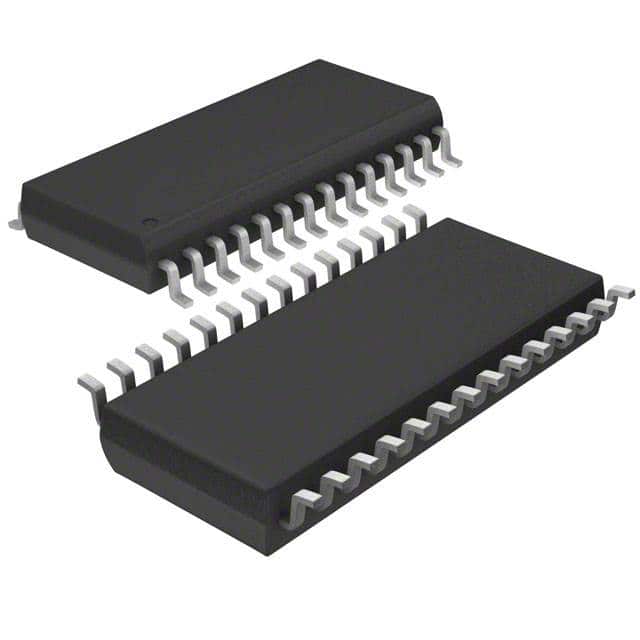
- Part No.:
- PI6C20400ALE
- Manufacturer:
- Diodes Incorporated
- Category:
- Application Specific Clock/Timing
- Package:
- 28-TSSOP (0.173", 4.40mm Width)
- Datasheet:
-
 PI6C20400ALE.pdf
- Description:
- IC CLOCK BUFFER 1:4 28TSSOP
- Quantity:
- Payment:

- Shipping:

Inventory:1,838
Please send an inquiry. Send us your inquiry, and we will respond immediately.
Product details
Overview
PI6C20400ALE from Pericom Semiconductor is a PCIe® 2.0-compliant differential clock buffer that distributes one differential SRC clock input to four differential output pairs, supporting both PLL (100 MHz) and bypass (100–400 MHz) modes. It features <1 ps additive RMS phase jitter, <50 ps cycle-to-cycle jitter, low skew (<50 ps), SMBus-controlled tristate outputs, and programmable PLL bandwidth. Used in Intel PCIe chipset companion clock distribution.
For engineers reviewing the PI6C20400ALE datasheet, PI6C20400ALE pinout, PI6C20400ALE application, or PI6C20400ALE equivalent, key selection criteria include PCIe 2.0 phase jitter compliance, differential output current control via IREF, dual-mode operation (PLL/BYPASS#), SMBus register access for output enable/inversion, and 28-pin TSSOP (L28) packaging with 3.3V supply.
Technical Context
The PI6C20400ALE implements a current-mode differential output stage with externally set output current (IREF = 2.32 mA, RREF = 475 Ω), delivering 0.7 V differential swing into 100 Ω loads. Its PLL supports 100 MHz operation with selectable bandwidth (high/low), while bypass mode enables wideband fanout from 100 MHz to 400 MHz.
Control logic integrates three independent enable paths: dedicated OE_0/OE_3 pins, global SRC_STOP#/PWRDWN# with OE_INV inversion option, and SMBus-configurable output enable/disable per channel. All outputs enter high-impedance state when PWRDWN# is asserted, with <300 µs drive disable timing and <1 ms stabilization on de-assertion.
Key Specifications
| Parameter | Value and Actual Design Meaning |
|---|---|
| Output Count | Four differential clock pairs (OUT0–OUT3 with complementary # signals) |
| Phase Jitter (Additive RMS) | <1 ps - meets PCIe 2.0 jitter budget for clean clock distribution |
| Jitter (Cycle-to-Cycle) | <50 ps - ensures tight timing margin in high-speed serial links |
| Skew (Output-to-Output) | <50 ps - maintains inter-pair alignment critical for multi-lane PCIe |
| Operating Modes | PLL mode (100 MHz) and bypass mode (100–400 MHz) - selectable via PLL/BYPASS# pin |
| Supply Voltage | 3.3 V ±5% for both core (VDD_A) and I/O (VDD) rails - standard PCIe voltage domain |
| Interface | SMBus slave with indexed block read/write - enables dynamic output control without hardware reconfiguration |
Pinout & Package
Package: 28-pin TSSOP (L28), 173-mil wide, Pb-free and RoHS-compliant.
| Pin/Terminal | Circuit Role | Design Meaning |
|---|---|---|
| SRC / SRC# | Differential clock input | Accepts 0.7 V differential SRC clock from companion synthesizer (e.g., PI6C410BS) |
| OUT0–OUT3 / OUT0#–OUT3# | Differential clock outputs | Eight pins delivering four 0.7 V differential pairs; current-mode buffered with IREF-set amplitude |
| OE_0 / OE_3 | Per-output enable inputs | 3.3 V LVTTL active-high enables for OUT0/OUT0# and OUT3/OUT3# respectively |
| OE_INV | Inversion control | Inverts logic polarity of OE_0, OE_3, SRC_STOP#, and PWRDWN# when high |
| PLL/BYPASS# | Mode select | Active-low selects PLL (100 MHz) or bypass (100–400 MHz) distribution path |
| SCLK / SDA | SMBus interface | Standard two-wire bus for reading/writing control registers (e.g., output enable, PLL BW) |
| IREF | Current reference | Connects external 475 Ω resistor to set nominal output current (2.32 mA → 13.9 mA per pair) |
| PWRDWN# / SRC_STOP# | Global output control | Active-low signals force all outputs to high-impedance; PWRDWN# also disables internal circuitry |
Key Features
| Feature | Design Value |
|---|---|
| PCIe 2.0 phase jitter compliance | <1 ps additive RMS jitter ensures signal integrity across Gen2 lanes without retiming |
| Programmable PLL bandwidth | Selectable high/low bandwidth via PLL_BW# pin or SMBus register - optimizes jitter suppression vs. lock time trade-off |
| Per-channel output enable | Independent OE_0/OE_3 + SMBus-configurable enable bits allow selective lane shutdown for power management |
| Current-mode differential outputs | Externally set output current (via IREF) delivers consistent 0.7 V swing into 100 Ω, minimizing trace-length sensitivity |
| Tristate control hierarchy | Hardware (SRC_STOP#, PWRDWN#) and software (SMBus) control layers provide robust system-level clock gating |
Applications
| PCIe Root Complex Clock Distribution | Server Backplane Timing Hub |
|---|---|
Use Scenario: Distributing reference clock from PI6C410BS to multiple PCIe slots in a server motherboard. IC Role / Device Role / Timing Role: Companion clock buffer providing four matched differential outputs with sub-50 ps skew for Gen2 link training. Use Value: Enables simultaneous initialization of up to four PCIe x16 slots while maintaining PCIe 2.0 jitter compliance across all lanes. | Use Scenario: Centralized clock fanout across modular backplane with hot-plug PCIe cards. IC Role / Device Role / Timing Role: High-reliability clock repeater with SMBus-configurable output enable per slot for dynamic power sequencing. Use Value: Reduces board-level routing complexity and eliminates point-to-point clock tree mismatches in multi-slot chassis designs. |
| Embedded Storage Controller Timing | Industrial PCIe-Based Data Acquisition |
Use Scenario: Driving clocks to NVMe controller and PCIe switch in compact storage appliance. IC Role / Device Role / Timing Role: Low-jitter buffer operating in bypass mode at 250 MHz to support high-bandwidth flash interfaces. Use Value: Maintains deterministic timing for concurrent PCIe transfers without PLL-induced latency or phase noise. | Use Scenario: Clocking FPGA-based PCIe endpoints in ruggedized test equipment with thermal cycling. IC Role / Device Role / Timing Role: Industrial-grade clock distributor with -40°C to +85°C operation and robust ESD protection (2 kV HBM). Use Value: Ensures long-term timing stability under temperature variation and electrical noise common in factory-floor environments. |
Equivalent & Alternatives
The following parts are listed as comparable options for similar PCIe clock buffer applications.
| Alternative Part | Technical Difference | Application Difference | Selection Advice |
|---|---|---|---|
| IDT 8T49N241 | Integrated PLL with fractional-N synthesis; higher integration but no bypass mode | Requires full clock synthesis; not drop-in for PI6C410BS companion use | Choose when needing programmable output frequencies beyond fixed 100/200/400 MHz points |
| ON Semi NB3N502 | Fixed 100 MHz PLL-only operation; no SMBus interface or bypass mode | Limited to single-frequency PCIe 2.0 distribution; no software-controlled output enable | Choose for cost-sensitive, static-clock applications where flexibility is not required |
Compared with IDT 8T49N241 and ON Semi NB3N502, the PI6C20400ALE uniquely combines PCIe 2.0-compliant jitter performance, hardware-selectable PLL/bypass operation, and SMBus-configurable per-output control-making it optimal for Intel chipset-based systems requiring both flexibility and deterministic timing.
Availability
PI6C20400ALE is available at Aetrix Electronics and suitable for PCIe root complex clock distribution, server backplane timing hubs, embedded storage controller timing, and industrial PCIe-based data acquisition requiring stable component supply and long-term lifecycle support.
Supply support for PI6C20400ALE includes scheduled delivery planning, volume procurement assistance, BOM continuity management, traceable sourcing, and lifecycle availability coordination for OEM customers, industrial embedded developers, connected-device designers, and electronics production programs.
Manufacturer
Pericom Semiconductor was a fabless provider of high-performance timing, interface, and signal integrity solutions, acquired by Diodes Incorporated in 2016; its clock products remain widely deployed in enterprise and industrial platforms.
The PI6C20400A series targets PCIe 2.0 clock distribution architectures, specifically designed as a companion device to Pericom's PI6C410BS clock synthesizer for Intel chipset platforms.
FAQ
What is the function of the IREF pin, and how is it configured?
The IREF pin sets the differential output current using an external 475 Ω ±1% resistor connected to VDD. This establishes a nominal 2.32 mA reference current, which scales output drive strength to deliver 0.7 V differential swing into 100 Ω loads. The resistor must be placed close to the pin with minimal trace length to maintain accuracy and noise immunity.
How does the PLL/BYPASS# pin affect clock distribution behavior?
When PLL/BYPASS# is high, the device operates in bypass mode, passing the SRC input directly to outputs across 100–400 MHz. When low, it engages the internal PLL locked to 100 MHz, filtering input jitter and providing frequency-stable outputs. This pin enables hardware-selectable trade-offs between bandwidth and jitter cleanup without firmware involvement.
Can all four output pairs be independently enabled or disabled?
Yes - OE_0 and OE_3 provide hardware enable control for OUT0/OUT0# and OUT3/OUT3#. Additionally, SMBus registers (Data Byte 1, bits 1,2,5,6) allow per-output enable/disable of all four pairs. This dual-layer control supports both board-level design flexibility and runtime power management in host firmware.
What happens to outputs during PWRDWN# assertion, and what is the recovery timing?
Asserting PWRDWN# forces all outputs to high-impedance within <300 µs and reduces supply current to ≤40 mA (driven outputs) or ≤12 mA (tristated). Upon de-assertion, outputs stabilize within <1 ms. During this state, SCLK and SDA must be tri-stated to prevent bus contention, as the device acts as an SMBus slave only when powered.
PI6C20400ALE Specifications
- Product attributes
- Attribute value
- Manufacturer:
- Diodes Incorporated
- Series:
- -
- Package/Case:
- 28-TSSOP (0.173", 4.40mm Width)
- Packaging:
- Tube
- Product Status:
- Obsolete
- Programmable:
- Not Verified
- PLL:
- Yes
- Main Purpose:
- PCI Express (PCIe)
- Input:
- HCSL
- Output:
- HCSL
- Number of Circuits:
- 1
- Ratio - Input:Output:
- 1:4
- Differential - Input:Output:
- Yes/Yes
- Frequency - Max:
- 400MHz
- Voltage - Supply:
- 3.135V ~ 3.465V
- Operating Temperature:
- -40°C ~ 85°C
- Mounting Type:
- Surface Mount
- Grade:
- -
- Qualification:
- -
- Supplier Device Package:
- 28-TSSOP
PI6C20400ALE FAQ
1.How can I place an order for PI6C20400ALE through Aetrix?
Please submit a Request for Quotation (RFQ) for PI6C20400ALE on Aetrix. Our sales agent will provide a competitive quotation and guide you through the order confirmation once you accept the terms.
2.Are the price and stock information for PI6C20400ALE reliable?
The price and inventory of PI6C20400ALE are updated periodically and may fluctuate due to market conditions. Stock and pricing data are typically refreshed every 24 hours. Quotation validity for PI6C20400ALE is usually 5 days.
3.What payment methods are accepted for PI6C20400ALE?
We accept Wire Transfer, PayPal, Credit Card, Western Union, MoneyGram, and Escrow for PI6C20400ALE transactions.
Note: Certain payment methods may incur a processing fee.
4.How is shipping managed for PI6C20400ALE?
PI6C20400ALE orders can be shipped via leading logistics carriers, including DHL, UPS, FedEx, TNT, or Registered Mail.
Once your PI6C20400ALE order is processed, you will receive an email with the shipment details and tracking number.
Note: Tracking information may take up to 24 hours to appear. Express delivery typically takes 3–5 business days.
5.How can I obtain technical support or documentation for PI6C20400ALE?
For technical support, including PI6C20400ALE datasheets, pinout diagrams, or application guidance, please contact our engineering support team. They can provide detailed documentation and assistance for your PI6C20400ALE requirements.
6.How does Aetrix verify that PI6C20400ALE is sourced from the original manufacturer or authorized distributors?
All PI6C20400ALE products on Aetrix are procured from qualified distributors and authorized channels. Our dedicated quality assurance team conducts strict verification, including traceability checks and, if necessary, third-party testing. This ensures that PI6C20400ALE meets industry standards.
7.What is the process for return or replacement of PI6C20400ALE?
All PI6C20400ALE units undergo pre-shipment inspection (PSI). If there is an issue with PI6C20400ALE, returns or replacements are accepted under the following conditions:
1.Quantity discrepancies, incorrect items, or visible external defects (such as breakage or corrosion), acknowledged by Aetrix.
2.The issue is reported within 90 days of delivery.
3.The PI6C20400ALE part is unused and in its original packaging.
Return procedure for PI6C20400ALE:
1.Submit a request within 90 days.
2.Obtain a Return Material Authorization (RMA) from Aetrix.
PI6C20400ALE Tags

-
LMK00334RTVRQ1
Texas Instruments
.jpg)
-
DSC557-0344FI0T
Microchip Technology

-
9FGV0241AKILFT
Renesas Electronics Corporation

-
9DBL0452CKILFT
Renesas Electronics Corporation
-
DSC557-0344FL1T
Microchip Technology

-
RC19008AGND#KB0
Renesas Electronics Corporation
-
RC19008AGND#BB0
Renesas Electronics Corporation

-
9DB403DGILFT
Renesas Electronics Corporation

-
9DB233AGILFT
Renesas Electronics Corporation

-
9DB803DGILFT
Renesas Electronics Corporation
-
9FGL0851DKILFT
Renesas Electronics Corporation

-
AB-557-03-HCHC-F-L-C-T
Abracon LLC
Tech Hub

An engineering guide to LED driver operation, constant-current and constant-voltage outputs, linear and switching topologies, dimming, IC selection, calculations, replacement compatibility, and fault c…

Operational amplifier guide covering op amp basics, feedback, ideal vs real op amps, common configurations, buffer circuits, offset, bias current, gain-bandwidth, slew rate, rail-to-rail limits and sel…

Jumper cables guide covering safe connection order, red and black clamp placement, final ground connection, cable gauge, length, clamp quality, copper vs CCA cables, jump starter comparison and battery…

LDO regulator guide covering low dropout voltage, power dissipation, thermal design, PSRR, output noise, capacitor stability, adjustable LDO circuits, LDO vs buck converter and datasheet selection chec…

Conditional Access Module guide covering CAM meaning, CI/CI+ interface, smart card authorization, DVB security workflow, TV and set-top box compatibility, internal electronics, ESD protection, connecto…

Guide to electronic component obsolescence covering EOL risk, PCN/PDN notices, last-time buy planning, replacement options, form-fit-function validation, counterfeit risk and BOM lifecycle management.

18650 battery guide covering lithium-ion cell basics, 3.6V/3.7V voltage, 4.2V charging, mAh and Wh capacity, protected cells, chargers, BMS, series-parallel packs, holders, welding and sourcing checks.…

Hall effect sensor guide covering working principle, linear and digital sensors, Arduino circuits, current sensing, speed detection, automotive applications, A3144 examples, signal filtering and datash…

Product Change Notification guide for electronic components, covering PCN meaning, PCN vs PDN/EOL, common change types, risk levels, form-fit-function review, engineering validation, BOM control, LTB/L…

A practical guide to blend door actuators, covering HVAC function, symptoms, location, AC and heater issues, reset and calibration, replacement cost, electrical diagnosis, compatibility checks, and rep…


