
 My Inquiry
 My Account


Diodes Incorporated PI6C20800SVE
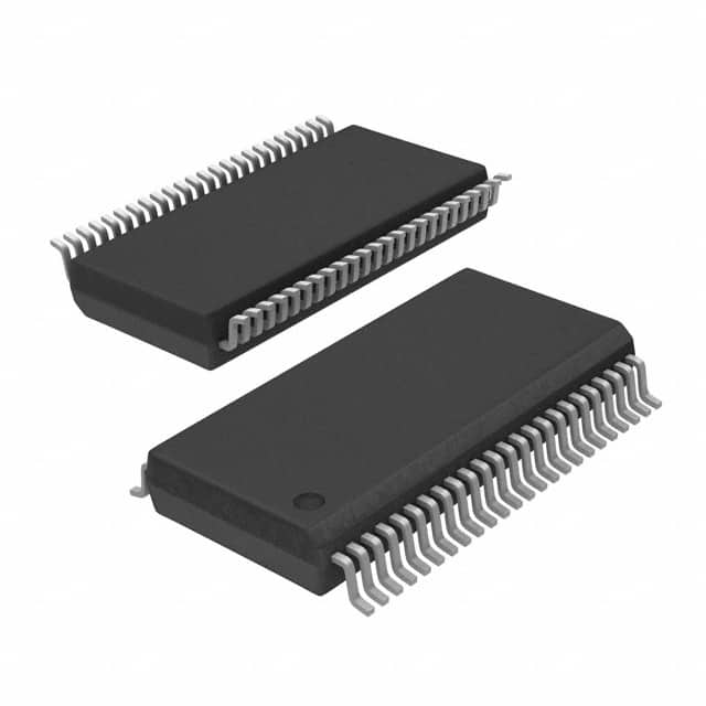
- Part No.:
- PI6C20800SVE
- Manufacturer:
- Diodes Incorporated
- Category:
- Application Specific Clock/Timing
- Package:
- 48-BSSOP (0.295", 7.50mm Width)
- Datasheet:
-
 PI6C20800SVE.pdf
- Description:
- IC CLOCK BUFFER 1:8 48TSSOP
- Quantity:
- Payment:

- Shipping:

Inventory:1,109
Please send an inquiry. Send us your inquiry, and we will respond immediately.
Product details
Overview
PI6C20800SVE from Pericom Semiconductor is a PCIe®-compliant 1:8 HCSL differential clock buffer with PLL/fanout mode selection, <50ps output skew (PI6C20800S), <70ps cycle-to-cycle jitter, and SMBus-controlled tristate outputs-designed as a companion to PI6C410BS for Intel server chipset clock distribution.
For engineers reviewing the PI6C20800SVE datasheet, PI6C20800SVE pinout, PI6C20800SVE application, or PI6C20800SVE equivalent, key selection criteria include differential HCSL output compliance, programmable PLL bandwidth, SRC_DIV# frequency division, SMBus-configurable OE control, and industrial-grade thermal operation up to +85°C.
Technical Context
This device operates in dual modes: PLL mode (95–105 MHz input, low additive jitter <1 ps RMS for PCIe 2.0) or bypass/fanout mode (95–400 MHz), with configurable PLL bandwidth via PLL_BW# and selectable input division by 2 when SRC_DIV# is asserted low.
It integrates an SMBus slave interface (7-bit address 0x6E) supporting indexed block read/write for register-level control of output enables, SRC_STOP#, PWRDWN#, and PLL/BYPASS selection-enabling dynamic power management and system-level clock gating without external logic.
Key Specifications
| Parameter | Value and Actual Design Meaning |
|---|---|
| Input Frequency Range | 95–105 MHz (PLL mode); 95–400 MHz (bypass mode)-supports PCIe Gen1/Gen2 reference clocks and flexible upstream source options. |
| Output Skew | <50 ps (PI6C20800S)-ensures timing alignment across eight HCSL differential pairs for multi-lane PCIe slot fanout. |
| Cycle-to-Cycle Jitter | <70 ps (differential waveform)-meets PCIe Gen2 jitter budget for stable high-speed serial link initialization. |
| Additive RMS Phase Jitter | <1 ps (PCIe 2.0 filter)-critical for maintaining eye margin in backplane and midplane clock distribution. |
| Supply Voltage | 3.3 V ±5% (VDD and VDD_A)-separate analog/digital rails enable clean PLL operation and robust I/O drive. |
| Operating Temperature | 0°C to +70°C (commercial)-validated for server motherboard environments with controlled airflow and thermal mass. |
| Differential Output Current | 13.9 mA nominal (6 × IREF, IREF = 2.32 mA @ RREF = 475 Ω)-matches HCSL-1 standard load (50 Ω termination to 0.7 V). |
Pinout & Package
PI6C20800SVE uses a 48-pin SSOP (300-mil wide, package code V), Pb-free and RoHS-compliant, with separate analog (VDD_A/VSS_A) and digital (VDD/VSS) power domains and dedicated IREF pin for precise current-mode output calibration.
| Pin/Terminal | Circuit Role | Design Meaning |
|---|---|---|
| SRC & SRC# | Differential input pair | Accepts 0.7 V HCSL reference clock from PI6C410BS; supports divide-by-2 via SRC_DIV# control. |
| OUT0–OUT7 & OUT0#–OUT7# | Differential HCSL outputs | Eight matched 0.7 V current-mode outputs; individually enabled via OE[0:7] or globally via SRC_STOP#/PWRDWN#. |
| OE[0:7], OE_INV | Output enable control | LVTTL inputs enabling/disabling each output pair; OE_INV inverts polarity of all OE, SRC_STOP#, and PWRDWN# signals. |
| SCLK / SDA | SMBus interface | Two-wire bus (7-bit address 0x6E) for runtime configuration of PLL mode, bandwidth, and output states. |
| PLL/BYPASS#, PLL_BW#, SRC_DIV#, SRC_STOP#, PWRDWN# | Mode and power control | Hardware-selectable functional modes; PWRDWN# forces outputs to high-impedance and reduces supply current to 12 µA (tristate). |
| LOCK | PLL lock indicator | Open-drain LVTTL output latched high when PLL achieves stable lock-used for BIOS/system readiness signaling. |
Key Features
| Feature | Design Value |
|---|---|
| Programmable PLL bandwidth | Selectable high/low bandwidth via PLL_BW# pin-optimizes jitter suppression vs. lock time trade-off for varying source stability. |
| SMBus-configurable output enables | Per-output OE[0:7] control via register writes-enables dynamic lane shutdown in multi-slot PCIe systems without hardware rework. |
| Current-mode HCSL outputs | 6× IREF output drive (IREF set by external 475 Ω resistor)-guarantees consistent 0.7 V common-mode and 100 Ω differential impedance into standard PCIe loads. |
| Low-power shutdown mode | PWRDWN# assertion reduces IDD to 12 µA (tristate) or 80 µA (driven)-supports platform-wide power gating during S3/S4 sleep states. |
| Industrial temperature option | PI6C20800SI variant rated –40°C to +85°C-qualified for telecom and embedded server applications with extended thermal cycling. |
Applications
| PCIe Gen2 Server Motherboard | Multi-Slot Add-in Card Carrier |
|---|---|
|
Use Scenario: Distributing a single PCIe reference clock from PI6C410BS to eight physical slots on a 2U rack server motherboard. IC Role / Device Role / Timing Role: 1:8 HCSL clock fanout buffer with PLL jitter filtering and per-slot enable control. Use Value: Maintains sub-50 ps inter-slot skew and <1 ps additive jitter-enabling simultaneous Gen2 link training across all slots without retiming. |
Use Scenario: Providing synchronized clocking to four dual-lane PCIe add-in cards mounted on a carrier board with hot-plug capability. IC Role / Device Role / Timing Role: SMBus-programmable clock buffer enabling per-card clock enable/disable during insertion/removal sequences. Use Value: Eliminates clock domain conflicts during hot-plug by asserting OE[n] before card presence detection-preventing spurious link flapping. |
| Intel C600/C610 Chipset Platform | PCIe Bridge Expansion Module |
|
Use Scenario: Clock distribution for CPU-attached PCIe root complexes and downstream switches in enterprise storage controllers. IC Role / Device Role / Timing Role: Companion buffer to PI6C410BS, supporting SRC_DIV#-based 100 MHz → 50 MHz down-division for legacy devices. Use Value: Enables backward compatibility with PCIe 1.1 peripherals while preserving Gen2 timing integrity on primary lanes. |
Use Scenario: Fanout from a PCIe switch's reference clock output to multiple endpoint devices on a mezzanine expansion module. IC Role / Device Role / Timing Role: Low-skew HCSL repeater with LOCK signal monitoring-used to validate clock stability before enabling switch configuration. Use Value: Prevents switch initialization failure by holding reset until LOCK goes high, confirming PLL lock prior to register access. |
Equivalent & Alternatives
The following parts are listed as comparable options for similar PCIe clock buffer applications.
| Alternative Part | Technical Difference | Application Difference | Selection Advice |
|---|---|---|---|
| IDT 8T49N241 | Integrated PLL with fractional-N synthesis; supports multiple output formats (LVDS, LVPECL, HCSL); higher pin count (64-QFN). | Used in mixed-signal timing systems requiring multi-protocol clock generation-not limited to PCIe-only fanout. | Select when needing programmable output formats or multi-frequency synthesis beyond fixed PCIe rates. |
| ON Semi NB3N502 | Fixed 1:2 HCSL fanout only; no PLL; no SMBus interface; lower skew (35 ps) but no programmability. | Targeted at cost-sensitive, static PCIe x16 bifurcation where dynamic control is unnecessary. | Select only for simple, unmanaged 1:2 fanout with minimal BOM count and zero firmware overhead. |
Compared with IDT 8T49N241 and ON Semi NB3N502, PI6C20800SVE offers balanced programmability and PCIe-specific optimization: SMBus configurability enables runtime adaptation, while its dedicated HCSL drive and <50 ps skew meet server motherboard layout constraints better than general-purpose alternatives.
Availability
PI6C20800SVE is available at Aetrix Electronics and suitable for PCIe Gen2 server motherboards, multi-slot add-in card carriers, and Intel C600/C610 chipset platforms requiring stable component supply, long-term lifecycle support, and Pb-free compliance.
Supply support for PI6C20800SVE includes scheduled delivery planning, volume procurement assistance, BOM continuity management, traceable sourcing, and lifecycle availability coordination for OEM customers, industrial embedded developers, connected-device designers, and electronics production programs.
Manufacturer
Pericom Semiconductor (acquired by Diodes Incorporated in 2016) specialized in high-performance timing, interface, and signal-integrity ICs for computing and communications infrastructure.
PI6C20800SVE belongs to Pericom's PCIe clock buffer product line, engineered specifically for low-jitter, low-skew fanout in Intel server chipset reference designs-prioritizing HCSL compliance, SMBus configurability, and thermal robustness over generic clock distribution.
FAQ
What is the function of the IREF pin on PI6C20800SVE?
The IREF pin connects to an external 475 Ω 1% resistor to set the reference current (IREF = 2.32 mA), which directly scales the 6× current-mode HCSL output drive strength. This ensures precise 0.7 V common-mode voltage and 100 Ω differential impedance into standard PCIe termination loads, maintaining signal integrity across process/voltage/temperature variations.
How does the LOCK signal behave during power-up and PLL locking?
The LOCK signal is an open-drain LVTTL output that remains low until the internal PLL achieves stable lock, then transitions high and latches. It stays asserted until power is cycled or PWRDWN# is asserted. This provides a hardware-observable, glitch-free indication for BIOS or FPGA logic to delay PCIe link initialization until clock stability is confirmed.
Can PI6C20800SVE operate without an external crystal or reference oscillator?
No. PI6C20800SVE is a clock buffer-not a clock generator-and requires an external differential HCSL reference clock (e.g., from PI6C410BS) applied to SRC/SRC#. It has no internal oscillator or crystal interface; its PLL only filters and redistributes the supplied input, with optional divide-by-2 via SRC_DIV#.
What is the maximum allowable capacitive load on each HCSL output pair?
Each OUT[n]/OUT[n]# pair is characterized for 2 pF total pin capacitance (including PCB trace and receiver input). Exceeding this degrades rise/fall times and increases jitter; the datasheet specifies Trise/Tfall limits (175–700 ps) and skew (≤50 ps) only under the defined test load (Rp = 49.9 Ω, Rs = 33 Ω, CL = 2 pF).
PI6C20800SVE Specifications
- Product attributes
- Attribute value
- Manufacturer:
- Diodes Incorporated
- Series:
- -
- Package/Case:
- 48-BSSOP (0.295", 7.50mm Width)
- Packaging:
- Tube
- Product Status:
- Obsolete
- Programmable:
- Not Verified
- PLL:
- Yes
- Main Purpose:
- PCI Express (PCIe)
- Input:
- HCSL
- Output:
- HCSL
- Number of Circuits:
- 1
- Ratio - Input:Output:
- 1:8
- Differential - Input:Output:
- Yes/Yes
- Frequency - Max:
- 400MHz
- Voltage - Supply:
- 3.135V ~ 3.465V
- Operating Temperature:
- 0°C ~ 70°C
- Mounting Type:
- Surface Mount
- Grade:
- -
- Qualification:
- -
- Supplier Device Package:
- 48-SSOP
PI6C20800SVE FAQ
1.How can I place an order for PI6C20800SVE through Aetrix?
Please submit a Request for Quotation (RFQ) for PI6C20800SVE on Aetrix. Our sales agent will provide a competitive quotation and guide you through the order confirmation once you accept the terms.
2.Are the price and stock information for PI6C20800SVE reliable?
The price and inventory of PI6C20800SVE are updated periodically and may fluctuate due to market conditions. Stock and pricing data are typically refreshed every 24 hours. Quotation validity for PI6C20800SVE is usually 5 days.
3.What payment methods are accepted for PI6C20800SVE?
We accept Wire Transfer, PayPal, Credit Card, Western Union, MoneyGram, and Escrow for PI6C20800SVE transactions.
Note: Certain payment methods may incur a processing fee.
4.How is shipping managed for PI6C20800SVE?
PI6C20800SVE orders can be shipped via leading logistics carriers, including DHL, UPS, FedEx, TNT, or Registered Mail.
Once your PI6C20800SVE order is processed, you will receive an email with the shipment details and tracking number.
Note: Tracking information may take up to 24 hours to appear. Express delivery typically takes 3–5 business days.
5.How can I obtain technical support or documentation for PI6C20800SVE?
For technical support, including PI6C20800SVE datasheets, pinout diagrams, or application guidance, please contact our engineering support team. They can provide detailed documentation and assistance for your PI6C20800SVE requirements.
6.How does Aetrix verify that PI6C20800SVE is sourced from the original manufacturer or authorized distributors?
All PI6C20800SVE products on Aetrix are procured from qualified distributors and authorized channels. Our dedicated quality assurance team conducts strict verification, including traceability checks and, if necessary, third-party testing. This ensures that PI6C20800SVE meets industry standards.
7.What is the process for return or replacement of PI6C20800SVE?
All PI6C20800SVE units undergo pre-shipment inspection (PSI). If there is an issue with PI6C20800SVE, returns or replacements are accepted under the following conditions:
1.Quantity discrepancies, incorrect items, or visible external defects (such as breakage or corrosion), acknowledged by Aetrix.
2.The issue is reported within 90 days of delivery.
3.The PI6C20800SVE part is unused and in its original packaging.
Return procedure for PI6C20800SVE:
1.Submit a request within 90 days.
2.Obtain a Return Material Authorization (RMA) from Aetrix.
PI6C20800SVE Tags

-
LMK00334RTVRQ1
Texas Instruments
.jpg)
-
DSC557-0344FI0T
Microchip Technology

-
9FGV0241AKILFT
Renesas Electronics Corporation

-
9DBL0452CKILFT
Renesas Electronics Corporation
-
DSC557-0344FL1T
Microchip Technology

-
RC19008AGND#KB0
Renesas Electronics Corporation
-
RC19008AGND#BB0
Renesas Electronics Corporation

-
9DB403DGILFT
Renesas Electronics Corporation

-
9DB233AGILFT
Renesas Electronics Corporation

-
9DB803DGILFT
Renesas Electronics Corporation
-
9FGL0851DKILFT
Renesas Electronics Corporation

-
AB-557-03-HCHC-F-L-C-T
Abracon LLC
Tech Hub

An engineering guide to LED driver operation, constant-current and constant-voltage outputs, linear and switching topologies, dimming, IC selection, calculations, replacement compatibility, and fault c…

Operational amplifier guide covering op amp basics, feedback, ideal vs real op amps, common configurations, buffer circuits, offset, bias current, gain-bandwidth, slew rate, rail-to-rail limits and sel…

Jumper cables guide covering safe connection order, red and black clamp placement, final ground connection, cable gauge, length, clamp quality, copper vs CCA cables, jump starter comparison and battery…

LDO regulator guide covering low dropout voltage, power dissipation, thermal design, PSRR, output noise, capacitor stability, adjustable LDO circuits, LDO vs buck converter and datasheet selection chec…

Conditional Access Module guide covering CAM meaning, CI/CI+ interface, smart card authorization, DVB security workflow, TV and set-top box compatibility, internal electronics, ESD protection, connecto…

Guide to electronic component obsolescence covering EOL risk, PCN/PDN notices, last-time buy planning, replacement options, form-fit-function validation, counterfeit risk and BOM lifecycle management.

18650 battery guide covering lithium-ion cell basics, 3.6V/3.7V voltage, 4.2V charging, mAh and Wh capacity, protected cells, chargers, BMS, series-parallel packs, holders, welding and sourcing checks.…

Hall effect sensor guide covering working principle, linear and digital sensors, Arduino circuits, current sensing, speed detection, automotive applications, A3144 examples, signal filtering and datash…

Product Change Notification guide for electronic components, covering PCN meaning, PCN vs PDN/EOL, common change types, risk levels, form-fit-function review, engineering validation, BOM control, LTB/L…

A practical guide to blend door actuators, covering HVAC function, symptoms, location, AC and heater issues, reset and calibration, replacement cost, electrical diagnosis, compatibility checks, and rep…


