
 My Inquiry
 My Account


Diodes Incorporated PI6C4911510FAIE
- Part No.:
- PI6C4911510FAIE
- Manufacturer:
- Diodes Incorporated
- Category:
- Clock Buffers, Drivers
- Package:
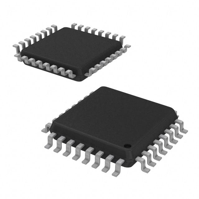
- 32-TQFP
- Datasheet:
-
 PI6C4911510FAIE.pdf
- Description:
- IC CLK BUFFER 2:10 1.5GHZ 32TQFP
- Quantity:
- Payment:

- Shipping:

Inventory:240
Please send an inquiry. Send us your inquiry, and we will respond immediately.
Product details
Overview
PI6C4911510FAIE from Pericom Semiconductor is a 1-to-10 differential LVPECL fanout buffer with dual selectable differential clock inputs (CLK0/CLK1), 1.5 GHz max frequency, <0.03 ps typical additive jitter, and 40 ps typical output skew. It supports LVPECL, LVDS, CML, and SSTL input levels and operates from 2.5 V ±5% or 3.3 V ±10% core/output supplies across –40°C to +85°C - used in high-speed clock distribution for FPGA, ASIC, and SerDes timing systems.
For engineers reviewing the PI6C4911510FAIE datasheet, PI6C4911510FAIE pinout, PI6C4911510FAIE application, or PI6C4911510FAIE equivalent, key selection criteria include differential input mux control (CLK_SEL), LVPECL output termination requirements (50 Ω to VDDO–2.0 V), supply separation (VDD/VDDO/VEE), thermal resistance (ΘJA = 86 °C/W for TQFP), and compatibility with low-noise SaRonix-eCera oscillators.
Technical Context
The PI6C4911510 implements a 2:1 differential clock multiplexer feeding a low-skew fanout stage with ten matched LVPECL output pairs. Its internal biasing supports single-ended input conversion via external VDD/2 reference, and its dual power domains (VDD for core logic, VDDO for outputs, VEE for LVPECL common-mode) enable independent supply optimization.
Output timing integrity is maintained through matched trace routing on-die and strict layout guidance: each power pin requires dedicated 0.1 µF + 1 µF bypassing, and LVPECL outputs must terminate differentially to VDDO–2.0 V. Additive jitter is measured RMS over 12 kHz–20 MHz (27 fs typical), validated against phase noise subtraction methodology.
Key Specifications
| Parameter | Value and Actual Design Meaning |
|---|---|
| Max Frequency | 1.5 GHz - supports PCIe Gen4, DDR4, and 10G Ethernet reference clocks. |
| Additive Jitter (RMS) | 0.03 ps typ - enables sub-100-fs system-level jitter budgets in high-speed serial links. |
| Output-to-Output Skew | 40 ps typ - ensures deterministic timing alignment across all 10 LVPECL output pairs. |
| Input Compatibility | LVPECL / LVDS / CML / SSTL - eliminates level-shifting ICs in mixed-signal clock trees. |
| Supply Voltages | VDD = 2.375–3.6 V; VDDO = 2.375–3.6 V; VEE = ground - allows flexible rail selection per domain. |
| Operating Temperature | –40°C to +85°C - qualified for industrial and telecom infrastructure environments. |
| Output Swing | 0.6–1.0 Vpp differential - meets LVPECL standard under 50 Ω termination to VDDO–2.0 V. |
Pinout & Package
PI6C4911510FAIE is packaged in a Pb-free, green 32-pin Thin Quad Flat Package (TQFP, code FA), 7 mm × 7 mm, 0.8 mm pitch, with exposed thermal pad (no E-pad variant specified for FAIE suffix). Package thermal resistance is ΘJA = 86 °C/W (still air).
| Pin/Terminal | Circuit Role | Design Meaning |
|---|---|---|
| VDD (Pin 1) | Core Power Supply | Supplies 2.5 V or 3.3 V to internal logic and input receivers; requires local 0.1 µF + 1 µF bypassing. |
| CLK_SEL (Pin 2) | Digital Control Input | LVTTL/LVCMOS-selectable mux: low = CLK0 active, high = CLK1 active; 50 kΩ internal pulldown. |
| CLK0, /CLK0 (Pins 3,4) | Differential Clock Input Pair | Accepts LVPECL/LVDS/CML/SSTL; /CLK0 defaults to VDD/2 if floating - enables single-ended use with external bias. |
| VBB (Pin 5, NC) | Internal Bias Node | No-connect; internal common-mode voltage node - must be left unconnected per datasheet. |
| CLK1, /CLK1 (Pins 6,7) | Differential Clock Input Pair | Second independent input path identical to CLK0 pair; supports redundant or multi-source clocking. |
| VEE (Pin 8) | Negative Supply Reference | Ground reference for LVPECL output stage; ties to system GND, not negative rail. |
| VDDO (Pins 9,16,25,32) | Output Power Supply | Separate 2.5 V or 3.3 V rail for all 10 LVPECL output drivers; decoupling critical for jitter performance. |
| Q0–Q9, /Q0–/Q9 (Pins 10–15,17–24,26–31) | Differential LVPECL Outputs | 10 matched output pairs; each requires 50 Ω termination to VDDO–2.0 V for proper DC bias and swing. |
Key Features
| Feature | Design Value |
|---|---|
| Dual Differential Input Mux | Hardware-selectable CLK0 or CLK1 via single LVTTL input (CLK_SEL), enabling failover or source switching without software. |
| Low-Additive-Jitter Fanout | 0.03 ps typical RMS additive jitter preserves signal integrity when distributing ultra-low-jitter oscillator sources. |
| Multi-Standard Input Acceptance | Single device replaces multiple level translators - accepts LVPECL, LVDS, CML, and SSTL without external circuitry. |
| Separated Core/Output Supplies | Independent VDD (core) and VDDO (outputs) allow noise isolation and rail optimization - e.g., clean 2.5 V for outputs, 3.3 V for logic. |
| Industrial Temperature Range | –40°C to +85°C operation verified across full voltage and load conditions - suitable for base station and networking hardware. |
Applications
| 5G Baseband Processing | FPGA High-Speed I/O Clocking |
|---|---|
Use Scenario: Distributing synchronized reference clocks to multiple ADC/DAC channels and digital front-end blocks in massive MIMO radio units. IC Role / Device Role / Timing Role: Low-skew 1-to-10 LVPECL fanout buffer with dual-input redundancy for primary/backup clock sources. Use Value: 40 ps output skew ensures deterministic sampling across 10+ data converters; <0.03 ps additive jitter maintains EVM compliance at 28 GHz carrier frequencies. | Use Scenario: Driving bank-specific clock inputs for transceivers, memory controllers, and hard IP blocks in Xilinx Versal or Intel Agilex FPGAs. IC Role / Device Role / Timing Role: Clock distribution hub translating a single oscillator output into ten phase-aligned LVPECL clocks with independent termination. Use Value: Dual input mux (CLK_SEL) enables dynamic reconfiguration between system clock and test pattern generator during validation. |
| Optical Transport Networking | High-Performance Computing Interconnect |
Use Scenario: Providing synchronized timing to multiple SerDes lanes in OTU4 (112 Gbps) line cards and packet processors. IC Role / Device Role / Timing Role: Fanout buffer for ultra-low-jitter OCXO or TCXO sources feeding CDR circuits and gearbox logic. Use Value: 1.5 GHz bandwidth and LVDS/CML input compatibility allow direct connection to diverse timing sources without retiming. | Use Scenario: Clocking GPU memory interfaces (HBM2E), NVLink PHYs, and CPU interconnects in AI accelerators requiring sub-100 fs jitter budgets. IC Role / Device Role / Timing Role: High-fidelity clock replication node with matched propagation delay across all outputs. Use Value: Separated VDD/VDDO rails prevent digital switching noise from modulating analog-sensitive output stages - critical for BER <1e–15. |
Equivalent & Alternatives
The following parts are listed as comparable options for similar clock fanout buffer applications.
| Alternative Part | Technical Difference | Application Difference | Selection Advice |
|---|---|---|---|
| ICS85310AMLF | 10-output LVPECL fanout with single input only; no CLK_SEL mux; higher additive jitter (0.07 ps typ). | Lacks input redundancy; suited for fixed-source clock trees without switchover needs. | Select when cost sensitivity outweighs need for dual-input flexibility and lowest jitter. |
| PI6C4911508FAIE | 8-output version of same family; identical architecture, specs, and pinout except fewer outputs (Q8/Q9 omitted). | Reduces PCB real estate and BOM count where only eight outputs are required. | Choose for space-constrained designs with ≤8 downstream loads - drop-in compatible except output count. |
Compared with ICS85310AMLF and PI6C4911508FAIE, the PI6C4911510FAIE uniquely delivers both 10-output capacity and hardware-selectable dual inputs within the same low-jitter, multi-standard interface envelope - making it optimal for fault-tolerant, high-density timing architectures.
Availability
PI6C4911510FAIE is available at Aetrix Electronics and suitable for 5G infrastructure, FPGA-based prototyping, and optical transport equipment requiring stable component supply, long-lifecycle support, and Pb-free/Green compliance.
Supply support for PI6C4911510FAIE includes scheduled delivery planning, volume procurement assistance, BOM continuity management, traceable sourcing, and lifecycle availability coordination for OEM customers, industrial embedded developers, connected-device designers, and electronics production programs.
Manufacturer
Pericom Semiconductor (acquired by Diodes Incorporated in 2017) specialized in high-performance timing, interface, and signal-integrity solutions for communications, computing, and industrial markets.
The PI6C49115xx family targets high-speed clock distribution in systems demanding ultra-low jitter, multi-standard input compatibility, and robust thermal performance - especially in dense, thermally constrained PCB layouts.
FAQ
What input termination is required for LVDS signals on CLK0/CLK1?
LVDS inputs require 100 Ω differential termination across CLK0 and /CLK0 (or CLK1 and /CLK1) at the PI6C4911510FAIE input pins. No external biasing is needed - the device's internal termination and common-mode range (VEE+0.5 V to VDD) accommodate standard LVDS voltage swings directly.
Can PI6C4911510FAIE drive unterminated LVPECL loads?
No. All LVPECL outputs (Q0–Q9) must be terminated differentially with 50 Ω to VDDO–2.0 V per pair. Unterminated or incorrectly terminated outputs cause signal reflection, degraded swing, increased jitter, and potential damage due to improper DC biasing of the emitter-coupled output stage.
Is VBB (Pin 5) required to be connected for single-ended input operation?
No. VBB is an internal common-mode node and must remain unconnected (NC) per datasheet. For single-ended input, external resistive divider (R1/R2) generates VDD/2 bias at /CLK0 or /CLK1 - VBB plays no role in that configuration and should not be routed or soldered.
How does thermal performance differ between FA (TQFP) and ZH (QFN) packages?
The FA package (PI6C4911510FAIE) has ΘJA = 86 °C/W (still air), while the ZH QFN variant achieves ΘJA = 44.7 °C/W due to superior thermal conduction via its exposed pad. For high-power or compact layouts, ZH reduces junction temperature rise by ~45%, improving long-term reliability and jitter stability under continuous 1.5 GHz operation.
PI6C4911510FAIE Specifications
- Product attributes
- Attribute value
- Manufacturer:
- Diodes Incorporated
- Series:
- -
- Package/Case:
- 32-TQFP
- Packaging:
- Tray
- Product Status:
- Active
- Type:
- Fanout Buffer (Distribution), Multiplexer
- Number of Circuits:
- 1
- Ratio - Input:Output:
- 2:10
- Differential - Input:Output:
- Yes/Yes
- Input:
- CML, LVDS, LVPECL, SSTL
- Output:
- LVPECL
- Frequency - Max:
- 1.5 GHz
- Voltage - Supply:
- 2.375V ~ 3.6V
- Operating Temperature:
- -40°C ~ 85°C
- Mounting Type:
- Surface Mount
- Grade:
- -
- Qualification:
- -
- Supplier Device Package:
- 32-TQFP (7x7)
PI6C4911510FAIE FAQ
1.How can I place an order for PI6C4911510FAIE through Aetrix?
Please submit a Request for Quotation (RFQ) for PI6C4911510FAIE on Aetrix. Our sales agent will provide a competitive quotation and guide you through the order confirmation once you accept the terms.
2.Are the price and stock information for PI6C4911510FAIE reliable?
The price and inventory of PI6C4911510FAIE are updated periodically and may fluctuate due to market conditions. Stock and pricing data are typically refreshed every 24 hours. Quotation validity for PI6C4911510FAIE is usually 5 days.
3.What payment methods are accepted for PI6C4911510FAIE?
We accept Wire Transfer, PayPal, Credit Card, Western Union, MoneyGram, and Escrow for PI6C4911510FAIE transactions.
Note: Certain payment methods may incur a processing fee.
4.How is shipping managed for PI6C4911510FAIE?
PI6C4911510FAIE orders can be shipped via leading logistics carriers, including DHL, UPS, FedEx, TNT, or Registered Mail.
Once your PI6C4911510FAIE order is processed, you will receive an email with the shipment details and tracking number.
Note: Tracking information may take up to 24 hours to appear. Express delivery typically takes 3–5 business days.
5.How can I obtain technical support or documentation for PI6C4911510FAIE?
For technical support, including PI6C4911510FAIE datasheets, pinout diagrams, or application guidance, please contact our engineering support team. They can provide detailed documentation and assistance for your PI6C4911510FAIE requirements.
6.How does Aetrix verify that PI6C4911510FAIE is sourced from the original manufacturer or authorized distributors?
All PI6C4911510FAIE products on Aetrix are procured from qualified distributors and authorized channels. Our dedicated quality assurance team conducts strict verification, including traceability checks and, if necessary, third-party testing. This ensures that PI6C4911510FAIE meets industry standards.
7.What is the process for return or replacement of PI6C4911510FAIE?
All PI6C4911510FAIE units undergo pre-shipment inspection (PSI). If there is an issue with PI6C4911510FAIE, returns or replacements are accepted under the following conditions:
1.Quantity discrepancies, incorrect items, or visible external defects (such as breakage or corrosion), acknowledged by Aetrix.
2.The issue is reported within 90 days of delivery.
3.The PI6C4911510FAIE part is unused and in its original packaging.
Return procedure for PI6C4911510FAIE:
1.Submit a request within 90 days.
2.Obtain a Return Material Authorization (RMA) from Aetrix.
PI6C4911510FAIE Tags

-
PL133-37TC-R
Microchip Technology
-
PL133-27GC-R
Microchip Technology
-
LMK1C1102DQFR
Texas Instruments

-
LMK1C1102PWR
Texas Instruments
-
LMK1C1104DQFR
Texas Instruments
-
LMK1C1104PWR
Texas Instruments
-
CDC3RL02YFPR
Texas Instruments

-
SY75602ATWL-TR
Microchip Technology
-
SY75603ATWL-TR
Microchip Technology
-
5PB1102CMGI8
Renesas Electronics Corporation
-
PL133-27GI-R
Microchip Technology

-
551MLFT
Renesas Electronics Corporation
Tech Hub

Operational amplifier guide covering op amp basics, feedback, ideal vs real op amps, common configurations, buffer circuits, offset, bias current, gain-bandwidth, slew rate, rail-to-rail limits and sel…

Jumper cables guide covering safe connection order, red and black clamp placement, final ground connection, cable gauge, length, clamp quality, copper vs CCA cables, jump starter comparison and battery…

LDO regulator guide covering low dropout voltage, power dissipation, thermal design, PSRR, output noise, capacitor stability, adjustable LDO circuits, LDO vs buck converter and datasheet selection chec…

Conditional Access Module guide covering CAM meaning, CI/CI+ interface, smart card authorization, DVB security workflow, TV and set-top box compatibility, internal electronics, ESD protection, connecto…

Guide to electronic component obsolescence covering EOL risk, PCN/PDN notices, last-time buy planning, replacement options, form-fit-function validation, counterfeit risk and BOM lifecycle management.

18650 battery guide covering lithium-ion cell basics, 3.6V/3.7V voltage, 4.2V charging, mAh and Wh capacity, protected cells, chargers, BMS, series-parallel packs, holders, welding and sourcing checks.…

Hall effect sensor guide covering working principle, linear and digital sensors, Arduino circuits, current sensing, speed detection, automotive applications, A3144 examples, signal filtering and datash…

Product Change Notification guide for electronic components, covering PCN meaning, PCN vs PDN/EOL, common change types, risk levels, form-fit-function review, engineering validation, BOM control, LTB/L…

A practical guide to blend door actuators, covering HVAC function, symptoms, location, AC and heater issues, reset and calibration, replacement cost, electrical diagnosis, compatibility checks, and rep…

Engineering guide to Raspberry Pi alternatives, covering chip-level differences, Orange Pi, ROCK, Jetson, Banana Pi, NanoPi, Compute Module, Pico, GPIO, camera, HAT compatibility, and replacement risks…


