
 My Inquiry
 My Account


Diodes Incorporated PI6ULS5V9511AUEX
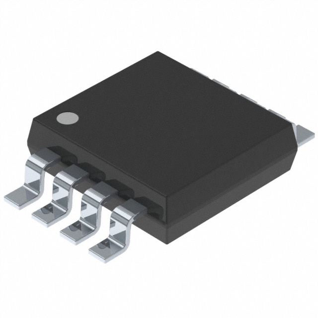
- Part No.:
- PI6ULS5V9511AUEX
- Manufacturer:
- Diodes Incorporated
- Category:
- Specialized
- Package:
- 8-TSSOP, 8-MSOP (0.118", 3.00mm Width)
- Datasheet:
-
 PI6ULS5V9511AUEX.pdf
- Description:
- IC HOT SWAP CTRLR 8MSOP
- Quantity:
- Payment:

- Shipping:

Inventory:4,613
Please send an inquiry. Send us your inquiry, and we will respond immediately.
Product details
Overview
PI6ULS5V9511A from Diodes Incorporated is a hot-swappable bidirectional I²C/SMBus buffer IC designed for live insertion into powered backplanes. It isolates SDA/SCL bus capacitance between card and backplane sides, supports clock stretching and multi-master arbitration, operates from 2.7V to 5.5V, and delivers up to 400kHz data rates with built-in 1.1V pre-charge and rise-time acceleration on all I²C lines.
For engineers reviewing the PI6ULS5V9511A datasheet, PI6ULS5V9511A pinout, PI6ULS5V9511A application, or PI6ULS5V9511A equivalent, this device addresses critical timing integrity, bus contention avoidance, and ESD-hardened hot-swap reliability in modular server, telecom line-card, and industrial rack-mount systems requiring live field-replaceable unit (FRU) support.
Technical Context
The PI6ULS5V9511A implements dual-channel bidirectional buffering with independent SDA and SCL paths, each featuring active pre-charge (1.1V), dynamic offset voltage control (110–175mV), and transient pullup current (≥2mA) triggered at 0.6V input threshold. Its startup logic enforces bus-idle or STOP-condition detection before connection, preventing corruption during hot insertion.
It integrates an open-drain READY output synchronized to internal connection state, an active-HIGH ENABLE with 110µs enable time, and high-impedance SDA/SCL pins at VCC = 0V. The device fully complies with I²C Standard Mode (100kHz), Fast Mode (400kHz), and SMBus specifications while supporting clock stretching and arbitration synchronization without protocol modification.
Key Specifications
| Parameter | Value and Actual Design Meaning |
|---|---|
| Supply Voltage | 2.7V to 5.5V - Enables interoperability across 3.3V and 5V I²C domains without level-shifting circuitry. |
| Max Data Rate | 400kHz - Fully supports I²C Fast Mode timing requirements including tLOW/tHIGH, tr/tf, and tSU:STA. |
| Pre-Charge Voltage | 1.1V ±0.3V - Minimizes inrush current during hot insertion by pre-biasing SDA/SCL lines before connection. |
| Rise-Time Acceleration | ≥2mA pulsed pullup - Meets 300ns rise-time requirement even with 400pF bus load and weak external pullups. |
| ESD Protection | 4000V HBM - Ensures robustness against handling-induced transients in manufacturing and field service environments. |
| Propagation Delay (tPHL) | 70ns max - Guarantees deterministic signal timing across buffered SDA/SCL paths under worst-case load conditions. |
| Input Capacitance | 5–7pF per SDA/SCL pin - Reduces effective bus loading, enabling longer trace lengths or higher node counts. |
Pinout & Package
PI6ULS5V9511A is available in MSOP-8 (U), UDFN-8 (ZW), and SOIC-8 (W) packages. All variants share identical pinout and functionality.
| Pin/Terminal | Circuit Role | Design Meaning |
|---|---|---|
| ENABLE (Pin 1) | Digital enable control input | Active-HIGH logic input that initiates initialization sequence; forces low-current disconnect when LOW. |
| SCLOUT (Pin 2) | SCL signal output to card side | Bidirectional SCL buffer output connected to card-side bus; mirrors SCLIN when enabled and synchronized. |
| SCLIN (Pin 3) | SCL signal input from backplane side | Bidirectional SCL buffer input connected to backplane bus; drives SCLOUT after idle/STOP detection. |
| GND (Pin 4) | Power ground reference | Primary return path for all internal circuits; must connect directly to low-impedance ground plane. |
| READY (Pin 5) | Open-drain status output | Indicates connection state: LOW = disconnected/idle; HIGH = SDA/SCL channels actively linked (3mA sink capability). |
| SDAIN (Pin 6) | SDA signal input from backplane side | Bidirectional SDA buffer input connected to backplane bus; drives SDAOUT after synchronization. |
| SDAOUT (Pin 7) | SDA signal output to card side | Bidirectional SDA buffer output connected to card-side bus; electrically isolated from SDAIN until READY HIGH. |
| VCC (Pin 8) | Positive supply rail | Power input for internal logic and rise-time accelerators; also serves as reference for pullup resistor selection. |
Key Features
| Feature | Design Value |
|---|---|
| Bidirectional I²C buffering with isolation | Maintains separate capacitive loads on backplane and card sides-enables >10× more nodes per bus segment. |
| Hot-swap safe startup sequence | Pre-charges SDA/SCL to 1.1V and waits for bus-idle or STOP condition before connecting-eliminates glitches during FRU insertion. |
| Rise-time accelerator circuitry | Activates ≥2mA transient pullup when input crosses 0.6V-ensures <300ns rise time even with 400pF load and 10kΩ pullup. |
| READY status flag with open-drain output | Provides system-level visibility into buffer connection state-enables host controller to gate downstream I²C transactions. |
| Full I²C Fast Mode + SMBus compliance | Meets all timing parameters (tSP, tSU:DAT, tHD:STA, etc.) at 400kHz-no firmware or protocol changes required. |
Applications
| Telecom Line Cards | Industrial Rack-Mount Controllers |
|---|---|
|
Use Scenario: Hot-plug I/O modules inserted into live carrier boards in central office switching systems. IC Role / Device Role / Timing Role: I²C bus buffer isolating module-side EEPROMs, temperature sensors, and PMBus power controllers from shared backplane bus. Use Value: Prevents bus lockup during insertion by enforcing STOP/idle detection before connection and suppressing SDA/SCL corruption via 1.1V pre-charge. |
Use Scenario: Modular PLC I/O expansion chassis where analog/digital modules are replaced without powering down the main controller. IC Role / Device Role / Timing Role: Bidirectional I²C repeater enabling clock stretching and arbitration between master CPU and slave sensor/actuator modules. Use Value: Maintains 400kHz timing integrity across distributed nodes while limiting total bus capacitance seen by the master to <10pF per module. |
| Server FRU Management | Medical Equipment Hot-Swap Modules |
|
Use Scenario: Blade servers with hot-swappable compute, storage, and network blades communicating via SMBus for health monitoring and configuration. IC Role / Device Role / Timing Role: SMBus-compliant buffer ensuring reliable communication between baseboard management controller (BMC) and blade-side FRU EEPROMs. Use Value: Enables BMC to detect READY HIGH before initiating inventory reads-guarantees data consistency during live blade replacement. |
Use Scenario: Modular diagnostic imaging systems (e.g., MRI, CT) where detector or power-supply modules are serviced during scheduled maintenance windows. IC Role / Device Role / Timing Role: ESD-hardened (4000V HBM) I²C isolator protecting sensitive analog front-end calibration data stored in on-module EEPROMs. Use Value: Eliminates risk of corrupted calibration data writes during module insertion due to transient coupling-meets IEC 60601-1 safety requirements. |
Equivalent & Alternatives
The following parts are listed as comparable options for similar I²C hot-swap buffer applications.
| Alternative Part | Technical Difference | Application Difference | Selection Advice |
|---|---|---|---|
| TI TCA9517PWR | Single-channel I²C repeater with auto-direction sensing; no pre-charge or READY output; 3.3V-only supply. | Lacks hot-swap sequencing logic and bus-idle detection-requires external control for safe insertion. | Select when cost-sensitive, single-bus isolation is sufficient and system can manage enable timing externally. |
| NXP PCA9515DP | Two-channel buffer with 1.8V–5.5V operation but no rise-time accelerator or READY flag; supports only Standard Mode (100kHz). | No 400kHz Fast Mode support or dynamic pre-charge-unsuitable for high-speed FRU enumeration or PMBus power telemetry. | Select for legacy 100kHz systems where voltage flexibility matters more than timing margin or hot-swap assurance. |
Compared with TCA9517PWR and PCA9515DP, the PI6ULS5V9511A uniquely combines 400kHz timing compliance, integrated READY signaling, and hardware-enforced hot-swap safety-making it the only option that eliminates software coordination overhead for live FRU replacement in mission-critical infrastructure.
Availability
PI6ULS5V9511A is available at Aetrix Electronics and suitable for telecom line cards, industrial rack-mount controllers, server FRU management, and medical equipment hot-swap modules requiring stable component supply, long-term lifecycle support, and RoHS-compliant packaging.
Supply support for PI6ULS5V9511A includes scheduled delivery planning, volume procurement assistance, BOM continuity management, traceable sourcing, and lifecycle availability coordination for OEM customers, industrial embedded developers, connected-device designers, and electronics production programs.
Manufacturer
Diodes Incorporated is a global manufacturer of discrete semiconductors and analog ICs, specializing in high-reliability interface, power management, and signal integrity solutions for industrial, computing, and communications markets.
The PI6ULS5V9511A belongs to Diodes' Ultra-Low Skew (ULS) I²C buffer product line, engineered specifically for hot-pluggable modular systems where bus integrity during live insertion is non-negotiable.
FAQ
What is the purpose of the READY pin, and how should it be used in system design?
The READY pin is an open-drain output indicating whether the internal SDA/SCL channels are electrically connected (READY HIGH) or isolated (READY LOW). It goes HIGH only after ENABLE is asserted HIGH and the bus has been idle or issued a STOP condition. System designers must tie READY to a microcontroller GPIO with a 10kΩ pullup to VCC and gate downstream I²C transactions until READY asserts-ensuring no data is sent before the buffer completes its safe connection sequence.
Can PI6ULS5V9511A operate with different supply voltages on the backplane and card sides?
No-the PI6ULS5V9511A requires a single VCC supply (2.7V–5.5V) that powers both sides of the buffer. Its rise-time accelerators depend on VCC matching the external pullup voltage, and its pre-charge circuit references VCC. Using separate supplies would violate the 0.6V activation threshold and disable acceleration, leading to non-compliant rise times and potential I²C timeouts.
How does the 1.1V pre-charge function prevent bus corruption during hot insertion?
During insertion, the backplane SDA/SCL lines may be at logic HIGH (e.g., 3.3V) while the card-side lines float near 0V. Without pre-charge, connecting them causes large transient currents that distort bus waveforms and trigger false START/STOP conditions. The 1.1V pre-charge pulls both sides to a common intermediate voltage before connection, reducing peak current to <100µA and eliminating glitches that could halt I²C arbitration or corrupt EEPROM writes.
What is the maximum number of PI6ULS5V9511A buffers that can be cascaded in series on one I²C bus?
Diodes recommends no more than two PI6ULS5V9511A buffers in series. Each adds ~110–175mV dynamic offset voltage, and after three buffers, the cumulative offset risks exceeding the 0.6V rising-edge accelerator threshold-causing false clock edges during clock stretching. With light loading and VOL ≤ 0.1V at the master, four buffers may function marginally, but reliability degrades significantly above two due to timing uncertainty and noise susceptibility.
PI6ULS5V9511AUEX Specifications
- Product attributes
- Attribute value
- Manufacturer:
- Diodes Incorporated
- Series:
- -
- Package/Case:
- 8-TSSOP, 8-MSOP (0.118", 3.00mm Width)
- Packaging:
- Tape & Reel (TR)
- Product Status:
- Active
- Applications:
- -
- Interface:
- I2C, I2C Fast, SMBus
- Voltage - Supply:
- 2.7V ~ 5.5V
- Supplier Device Package:
- 8-MSOP
- Grade:
- -
- Qualification:
- -
- Mounting Type:
- Surface Mount
PI6ULS5V9511AUEX FAQ
1.How can I place an order for PI6ULS5V9511AUEX through Aetrix?
Please submit a Request for Quotation (RFQ) for PI6ULS5V9511AUEX on Aetrix. Our sales agent will provide a competitive quotation and guide you through the order confirmation once you accept the terms.
2.Are the price and stock information for PI6ULS5V9511AUEX reliable?
The price and inventory of PI6ULS5V9511AUEX are updated periodically and may fluctuate due to market conditions. Stock and pricing data are typically refreshed every 24 hours. Quotation validity for PI6ULS5V9511AUEX is usually 5 days.
3.What payment methods are accepted for PI6ULS5V9511AUEX?
We accept Wire Transfer, PayPal, Credit Card, Western Union, MoneyGram, and Escrow for PI6ULS5V9511AUEX transactions.
Note: Certain payment methods may incur a processing fee.
4.How is shipping managed for PI6ULS5V9511AUEX?
PI6ULS5V9511AUEX orders can be shipped via leading logistics carriers, including DHL, UPS, FedEx, TNT, or Registered Mail.
Once your PI6ULS5V9511AUEX order is processed, you will receive an email with the shipment details and tracking number.
Note: Tracking information may take up to 24 hours to appear. Express delivery typically takes 3–5 business days.
5.How can I obtain technical support or documentation for PI6ULS5V9511AUEX?
For technical support, including PI6ULS5V9511AUEX datasheets, pinout diagrams, or application guidance, please contact our engineering support team. They can provide detailed documentation and assistance for your PI6ULS5V9511AUEX requirements.
6.How does Aetrix verify that PI6ULS5V9511AUEX is sourced from the original manufacturer or authorized distributors?
All PI6ULS5V9511AUEX products on Aetrix are procured from qualified distributors and authorized channels. Our dedicated quality assurance team conducts strict verification, including traceability checks and, if necessary, third-party testing. This ensures that PI6ULS5V9511AUEX meets industry standards.
7.What is the process for return or replacement of PI6ULS5V9511AUEX?
All PI6ULS5V9511AUEX units undergo pre-shipment inspection (PSI). If there is an issue with PI6ULS5V9511AUEX, returns or replacements are accepted under the following conditions:
1.Quantity discrepancies, incorrect items, or visible external defects (such as breakage or corrosion), acknowledged by Aetrix.
2.The issue is reported within 90 days of delivery.
3.The PI6ULS5V9511AUEX part is unused and in its original packaging.
Return procedure for PI6ULS5V9511AUEX:
1.Submit a request within 90 days.
2.Obtain a Return Material Authorization (RMA) from Aetrix.
PI6ULS5V9511AUEX Tags

-
NVT4857UKAZ
NXP Semiconductors

-
TCA8418RTWR
Texas Instruments

-
PCA9546APWR
Texas Instruments

-
MD0100N8-G
Microchip Technology

-
PCA9548APW,118
NXP Semiconductors

-
PCA9540BDP,118
NXP Semiconductors

-
PCA9548APWR
Texas Instruments

-
PCA9546APW,118
NXP Semiconductors

-
PTN3360DBS,518
NXP Semiconductors

-
PCA9546ABS,118
NXP Semiconductors

-
PCA9518PWR
Texas Instruments

-
PCA9545APW,118
NXP Semiconductors
Tech Hub

A practical engineering guide to 3.3V and 5V logic compatibility, input thresholds, resistor dividers, translator ICs, MOSFET level shifting, I2C pull-ups, timing limits and power-sequencing risks.

The 74HC595 uses push-pull logic outputs, while the TPIC6B595 uses 50 V open-drain DMOS sinks for higher-power loads. This guide compares timing, current limits, 3.3 V interfacing, load wiring, thermal…

The 74HC595 converts serial data into eight stable parallel outputs. This guide covers pin functions, shift and storage timing, OE and MR behavior, drive-current limits, cascading, voltage compatibilit…

A technical comparison of level-sensitive latches and edge-triggered flip-flops, covering timing windows, setup and hold limits, master–slave operation, time borrowing, race-through, HDL inference and…

A D latch stores one bit while Enable controls when data can pass. This reference covers gate-level operation, truth tables, transparency, setup and hold timing, LE versus OE, common ICs and practical …

An SR latch stores one bit through cross-coupled feedback. This engineering reference covers NOR and NAND implementations, truth tables, forbidden-state recovery, gated operation, switch debouncing, fa…

Latch circuits retain one bit through feedback. This technical reference covers SR and D latches, truth tables, transparency, timing limits, latch-versus-flip-flop behavior, applications and common log…

An engineering guide to LED driver operation, constant-current and constant-voltage outputs, linear and switching topologies, dimming, IC selection, calculations, replacement compatibility, and fault c…

Operational amplifier guide covering op amp basics, feedback, ideal vs real op amps, common configurations, buffer circuits, offset, bias current, gain-bandwidth, slew rate, rail-to-rail limits and sel…

Jumper cables guide covering safe connection order, red and black clamp placement, final ground connection, cable gauge, length, clamp quality, copper vs CCA cables, jump starter comparison and battery…


