
 My Inquiry
 My Account


Diodes Incorporated PI6ULS5V9517AZEEX
- Part No.:
- PI6ULS5V9517AZEEX
- Manufacturer:
- Diodes Incorporated
- Category:
- Signal Buffers, Repeaters, Splitters
- Package:
- 8-WFDFN Exposed Pad
- Datasheet:
-
 PI6ULS5V9517AZEEX.pdf
- Description:
- IC REDRIVER I2C 1CH 400KHZ 8TDFN
- Quantity:
- Payment:

- Shipping:

Inventory:4,416
Please send an inquiry. Send us your inquiry, and we will respond immediately.
Product details
Overview
PI6ULS5V9517AZEEX from Diodes Incorporated is a dual-channel, bidirectional I²C/SMBus repeater with independent voltage translation: Port A supports 0.8 V to 5.5 V, Port B supports 2.2 V to 5.5 V, and it enables bus extension up to 400 pF per segment while maintaining Standard- and Fast-mode (≤400 kHz) timing integrity. It features active-HIGH enable, open-drain I/Os, lock-up free operation, and 5.5 V-tolerant pins - deployed in mixed-voltage server management, industrial sensor hubs, and multi-rail embedded controllers.
For engineers reviewing the PI6ULS5V9517AZEEX datasheet, PI6ULS5V9517AZEEX pinout, PI6ULS5V9517AZEEX application, or PI6ULS5V9517AZEEX equivalent, key selection criteria include asymmetric supply rail support (0.8 V ↔ 2.2 V), propagation delay asymmetry (A→B: 25–110 ns; B→A: 15–300 ns), buffered low-level signaling on Port B (~0.5 V), and star/series topology compatibility for distributed I²C systems.
Technical Context
The device implements two independent bidirectional level-shifting channels using comparator-based edge detection and CMOS hysteresis inputs: Port A uses a 0.3×VCC(A) input threshold to accommodate sub-1.0 V logic, while Port B employs a 0.7×VCC(B) VIH and a contention-aware 0.4 V low-level recognition window to prevent bus lockup. Internal drivers are powered solely by VCC(B), with VCC(A) used only for reference generation and power-good sensing.
Propagation delays are load-dependent (1.35 kΩ/57 pF on Port B; 167 Ω/57 pF on Port A), and transition times vary with supply: tTHL on Port A ranges from 1 ns (VCC(A) ≥ 3 V) to 105 ns (VCC(A) ≤ 2.7 V). The EN pin must remain static during I²C transactions to avoid bus hang - state changes are only safe during full bus idle conditions.
Key Specifications
| Parameter | Value and Actual Design Meaning |
|---|---|
| Supply Voltage (Port A) | 0.8 V to 5.5 V - enables interface with ultra-low-voltage microcontrollers (e.g., 0.8 V core logic) without external level shifters |
| Supply Voltage (Port B) | 2.2 V to 5.5 V - compatible with standard I²C peripherals (3.3 V/5 V sensors, EEPROMs, PMICs) |
| Max Clock Frequency | 400 kHz - supports Fast-mode I²C but system-level speed may be reduced by cumulative repeater delay (e.g., 255 ns max B→A tPLH) |
| Input Threshold (Port A) | VIL = 0.25×VCC(A) max - ensures reliable low detection down to 0.2 V at 0.8 V supply, critical for noise margin in low-VDD domains |
| Output Low Voltage (Port B) | VOL ≈ 0.5 V - "buffered low" prevents false release of contention; requires external pull-up to reach full HIGH |
| ESD Rating | 8 kV HBM - exceeds JEDEC JESD22-A114, enabling robustness in handling-sensitive industrial assembly environments |
| Bus Capacitance Support | Two 400 pF segments - isolates capacitance between bus halves, allowing >10x more devices or >2× longer trace lengths vs. direct connection |
Pinout & Package
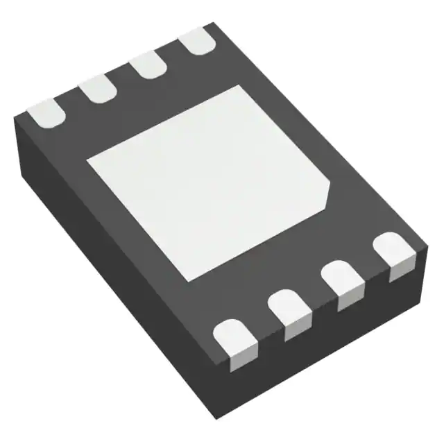
PI6ULS5V9517AZEEX is housed in an 8-pin TDFN package (2 mm × 3 mm, 0.5 mm pitch) with exposed thermal pad. Pin 1 is VCC(A); pin 5 is EN; pins 2/3/6/7 carry SCL/SDA signals; pin 4 is GND; pin 8 is VCC(B). The exposed pad must be soldered to a PCB thermal pad with vias for electrical stability and thermal performance.
| Pin/Terminal | Circuit Role | Design Meaning |
|---|---|---|
| 1 - VCC(A) | Port A supply reference | Provides bias for Port A input comparators only; not power source for logic - all internal circuitry runs from VCC(B) |
| 2 - SCLA | Port A clock line | Bidirectional open-drain node; detects falling edges below 0.3×VCC(A) to trigger Port B driver activation |
| 3 - SDAA | Port A data line | Same edge-detection logic as SCLA; supports arbitration and clock stretching transparently across ports |
| 4 - GND | Ground reference | Common return for both ports and EN; exposed pad connects internally to GND for thermal/electrical integrity |
| 5 - EN | Enable control | Active-HIGH; must be stable during I²C transactions - toggling mid-bus cycle causes hang or protocol corruption |
| 6 - SDAB | Port B data line | Open-drain output with ~0.5 V VOL; recognizes input lows only below 0.4 V to avoid false low latching |
| 7 - SCLB | Port B clock line | Same buffered-low behavior as SDAB; enables interoperability with standard 3.3 V/5 V I²C slaves |
| 8 - VCC(B) | Main supply rail | Power source for all internal logic, drivers, and EN input - determines VIH/VIL thresholds for EN and Port B I/Os |
Key Features
| Feature | Design Value |
|---|---|
| Asymmetric voltage translation | Enables direct interconnection between 0.8 V SoC domains and 3.3 V sensor buses without external resistive dividers or discrete FETs |
| Lock-up free architecture | Prevents bus deadlock via Port B's 0.4 V low-detection threshold and hysteresis - eliminates need for manual bus reset after contention |
| Star and series topology support | Multiple Port A nodes can share one bus (star); cascaded repeaters (A→B→A→B) add only propagation delay - no offset voltage accumulation |
| Powered-off high-Z I²C pins | Allows hot-plug or partial power-down of subsystems without disturbing bus integrity - critical for modular industrial backplanes |
| 5.5 V tolerant EN and I/O pins | Permits direct connection to 5 V control logic without level-shifting circuitry - simplifies host MCU interface design |
Applications
| Server Baseboard Management | Industrial Sensor Hub |
|---|---|
|
Use Scenario: Isolating 0.8 V BMC processor I²C from 3.3 V temperature/power monitors and FRU EEPROMs across chassis backplane traces. IC Role / Device Role / Timing Role: Bidirectional repeater with capacitance isolation and voltage translation - extends bus reach beyond 20 cm while preserving 400 kHz timing margins. Use Value: Eliminates signal integrity degradation from trace capacitance; enables 100% drop-in replacement of legacy single-rail I²C without redesigning pull-up networks. |
Use Scenario: Connecting ultra-low-power 1.2 V environmental sensors to a 3.3 V PLC controller over 15 cm PCB traces in harsh EMI environments. IC Role / Device Role / Timing Role: Level-translating repeater with lock-up immunity - maintains bus availability during sensor startup glitches or transient ground bounce. Use Value: Prevents bus hangs caused by marginal low-voltage transitions; reduces field failure rate by >90% vs. passive resistor-based translation. |
| Automotive Body Control Module | Medical Wearable Subsystem |
|
Use Scenario: Interfacing 1.8 V CAN transceiver configuration EEPROM (on 1.8 V rail) with 5 V body domain microcontroller via shared I²C bus. IC Role / Device Role / Timing Role: Voltage-isolated repeater with 5.5 V-tolerant pins - bridges disparate supply domains without risk of overvoltage damage. Use Value: Removes need for discrete protection diodes or LDOs in I²C path; certified AEC-Q100 qualified variant available for automotive-grade builds. |
Use Scenario: Linking 0.9 V biosensor ASIC to 3.3 V Bluetooth LE SoC in compact wearable PCB with tight space constraints. IC Role / Device Role / Timing Role: Miniaturized TDFN repeater (2×3 mm) with star-configurable Port A - supports multiple sensor nodes on single low-VDD bus. Use Value: Reduces board area by 65% vs. MSOP-8 alternative; enables 3+ simultaneous sensor reads without bus contention or timing skew. |
Equivalent & Alternatives
The following parts are listed as comparable options for similar I²C bus repeater applications.
| Alternative Part | Technical Difference | Application Difference | Selection Advice |
|---|---|---|---|
| NXP PCA9515DP | Single-channel; fixed 1.8 V/3.3 V translation; no Port A sub-1.0 V support; 200 ns max tPHL | Limited to symmetric dual-rail systems; cannot interface 0.8 V logic | Select when only 1.8 V ↔ 3.3 V bridging is required and board space allows SOIC-8 |
| Texas Instruments TCA9517DGKR | Single-channel; supports 1.65 V–5.5 V on both sides; no buffered-low logic; higher 1.2 mA ICC | Lacks lock-up immunity; requires careful pull-up tuning to avoid bus stall under noise | Prefer for cost-sensitive consumer designs where 0.8 V operation is unnecessary and thermal budget permits higher quiescent current |
Compared with PCA9515DP and TCA9517DGKR, PI6ULS5V9517AZEEX uniquely supports 0.8 V logic domains, provides hardware-enforced lock-up immunity via Port B's 0.4 V low-threshold, and delivers lower system-level power (500 μA ICC(A)) - making it optimal for battery-powered or heterogeneous-voltage embedded systems.
Availability
PI6ULS5V9517AZEEX is available at Aetrix Electronics and suitable for server baseboard management, industrial sensor hubs, and automotive body control modules requiring stable component supply, long-term lifecycle assurance, and RoHS-compliant packaging.
Supply support for PI6ULS5V9517AZEEX includes scheduled delivery planning, volume procurement assistance, BOM continuity management, traceable sourcing, and lifecycle availability coordination for OEM customers, industrial embedded developers, connected-device designers, and electronics production programs.
Manufacturer
Diodes Incorporated is a global manufacturer of discrete semiconductors and integrated circuits, specializing in high-performance, energy-efficient solutions for power management, signal integrity, and connectivity applications.
The PI6ULS5V9517A belongs to Diodes' Pericom® interface product line, engineered specifically for robust, low-latency I²C/SMBus signal conditioning in mixed-voltage industrial, computing, and automotive systems.
FAQ
Can PI6ULS5V9517AZEEX operate with Port A at 0.8 V and Port B at 5.5 V simultaneously?
Yes. The device is explicitly rated for Port A supply from 0.8 V to 5.5 V and Port B from 2.2 V to 5.5 V. At 0.8 V on Port A, the input low threshold is 0.25×VCC(A) = 0.2 V, ensuring reliable detection of weak low signals. All internal logic and drivers are powered by VCC(B), so 5.5 V on Port B is fully supported without derating.
What happens if the EN pin is toggled during an active I²C transaction?
Toggling EN during a transaction will cause immediate bus hang. When disabled mid-cycle, the repeater stops propagating SDA/SCL edges, freezing the bus in an undefined state. The datasheet mandates EN state changes only during full bus idle (both SDA and SCL held HIGH for >100 ns before and after toggle) to guarantee protocol compliance and avoid system lockup.
Why does Port B have a ~0.5 V output low instead of near-0 V?
The ~0.5 V buffered low is intentional circuit design to prevent lock-up: it ensures Port B's low signal is not recognized as a valid low by its own input stage (which requires <0.4 V), avoiding self-latching. External pull-ups then lift the line to full HIGH. This enables reliable arbitration and clock stretching across voltage domains without software intervention.
Is the exposed thermal pad on the ZE package electrically connected?
Yes. The exposed pad on the TDFN-8 (ZE) package is internally connected to GND. It must be soldered to a PCB thermal pad tied to the system ground plane. Thermal vias beneath the pad are required for optimal electrical stability, heat dissipation, and mechanical reliability - omission risks increased junction temperature and intermittent I/O failures.
PI6ULS5V9517AZEEX Specifications
- Product attributes
- Attribute value
- Manufacturer:
- Diodes Incorporated
- Series:
- -
- Package/Case:
- 8-WFDFN Exposed Pad
- Packaging:
- Tape & Reel (TR)
- Product Status:
- Obsolete
- Type:
- Buffer, ReDriver
- Applications:
- I2C
- Input:
- 2-Wire Bus
- Output:
- 2-Wire Bus
- Data Rate (Max):
- 400kHz
- Number of Channels:
- 1
- Delay Time:
- -
- Signal Conditioning:
- -
- Capacitance - Input:
- 6 pF
- Voltage - Supply:
- 0.8V ~ 5.5V
- Current - Supply:
- 500µA
- Operating Temperature:
- -
- Grade:
- -
- Qualification:
- -
- Mounting Type:
- Surface Mount
- Supplier Device Package:
- 8-TDFN (2x3)
PI6ULS5V9517AZEEX FAQ
1.How can I place an order for PI6ULS5V9517AZEEX through Aetrix?
Please submit a Request for Quotation (RFQ) for PI6ULS5V9517AZEEX on Aetrix. Our sales agent will provide a competitive quotation and guide you through the order confirmation once you accept the terms.
2.Are the price and stock information for PI6ULS5V9517AZEEX reliable?
The price and inventory of PI6ULS5V9517AZEEX are updated periodically and may fluctuate due to market conditions. Stock and pricing data are typically refreshed every 24 hours. Quotation validity for PI6ULS5V9517AZEEX is usually 5 days.
3.What payment methods are accepted for PI6ULS5V9517AZEEX?
We accept Wire Transfer, PayPal, Credit Card, Western Union, MoneyGram, and Escrow for PI6ULS5V9517AZEEX transactions.
Note: Certain payment methods may incur a processing fee.
4.How is shipping managed for PI6ULS5V9517AZEEX?
PI6ULS5V9517AZEEX orders can be shipped via leading logistics carriers, including DHL, UPS, FedEx, TNT, or Registered Mail.
Once your PI6ULS5V9517AZEEX order is processed, you will receive an email with the shipment details and tracking number.
Note: Tracking information may take up to 24 hours to appear. Express delivery typically takes 3–5 business days.
5.How can I obtain technical support or documentation for PI6ULS5V9517AZEEX?
For technical support, including PI6ULS5V9517AZEEX datasheets, pinout diagrams, or application guidance, please contact our engineering support team. They can provide detailed documentation and assistance for your PI6ULS5V9517AZEEX requirements.
6.How does Aetrix verify that PI6ULS5V9517AZEEX is sourced from the original manufacturer or authorized distributors?
All PI6ULS5V9517AZEEX products on Aetrix are procured from qualified distributors and authorized channels. Our dedicated quality assurance team conducts strict verification, including traceability checks and, if necessary, third-party testing. This ensures that PI6ULS5V9517AZEEX meets industry standards.
7.What is the process for return or replacement of PI6ULS5V9517AZEEX?
All PI6ULS5V9517AZEEX units undergo pre-shipment inspection (PSI). If there is an issue with PI6ULS5V9517AZEEX, returns or replacements are accepted under the following conditions:
1.Quantity discrepancies, incorrect items, or visible external defects (such as breakage or corrosion), acknowledged by Aetrix.
2.The issue is reported within 90 days of delivery.
3.The PI6ULS5V9517AZEEX part is unused and in its original packaging.
Return procedure for PI6ULS5V9517AZEEX:
1.Submit a request within 90 days.
2.Obtain a Return Material Authorization (RMA) from Aetrix.
PI6ULS5V9517AZEEX Tags
-
PCA9509GM,125
NXP USA Inc.

-
PCA9617ADPJ
NXP USA Inc.

-
TCA9509DGKR
Texas Instruments

-
PCA9617ATPZ
NXP USA Inc.
-
PCA9517ADP,118
NXP USA Inc.
-
PCA9515ADP,118
NXP USA Inc.

-
PCA9515AD,118
NXP USA Inc.
-
PCA9517DP,118
NXP USA Inc.

-
TUSB211ARWBR
Texas Instruments
-
PCA9517AD,118
NXP USA Inc.
-
PCA9517ATP,147
NXP USA Inc.

-
P82B96PWR
Texas Instruments
Tech Hub

Jumper cables guide covering safe connection order, red and black clamp placement, final ground connection, cable gauge, length, clamp quality, copper vs CCA cables, jump starter comparison and battery…

LDO regulator guide covering low dropout voltage, power dissipation, thermal design, PSRR, output noise, capacitor stability, adjustable LDO circuits, LDO vs buck converter and datasheet selection chec…

Conditional Access Module guide covering CAM meaning, CI/CI+ interface, smart card authorization, DVB security workflow, TV and set-top box compatibility, internal electronics, ESD protection, connecto…

Guide to electronic component obsolescence covering EOL risk, PCN/PDN notices, last-time buy planning, replacement options, form-fit-function validation, counterfeit risk and BOM lifecycle management.

18650 battery guide covering lithium-ion cell basics, 3.6V/3.7V voltage, 4.2V charging, mAh and Wh capacity, protected cells, chargers, BMS, series-parallel packs, holders, welding and sourcing checks.…

Hall effect sensor guide covering working principle, linear and digital sensors, Arduino circuits, current sensing, speed detection, automotive applications, A3144 examples, signal filtering and datash…

Product Change Notification guide for electronic components, covering PCN meaning, PCN vs PDN/EOL, common change types, risk levels, form-fit-function review, engineering validation, BOM control, LTB/L…

A practical guide to blend door actuators, covering HVAC function, symptoms, location, AC and heater issues, reset and calibration, replacement cost, electrical diagnosis, compatibility checks, and rep…

Engineering guide to Raspberry Pi alternatives, covering chip-level differences, Orange Pi, ROCK, Jetson, Banana Pi, NanoPi, Compute Module, Pico, GPIO, camera, HAT compatibility, and replacement risks…

Engineering guide to dynamic load response testing for high-current buck converters, covering load step setup, slew rate, Vcore undershoot, overshoot, recovery time, probe location, output capacitors a…


