
 My Inquiry
 My Account


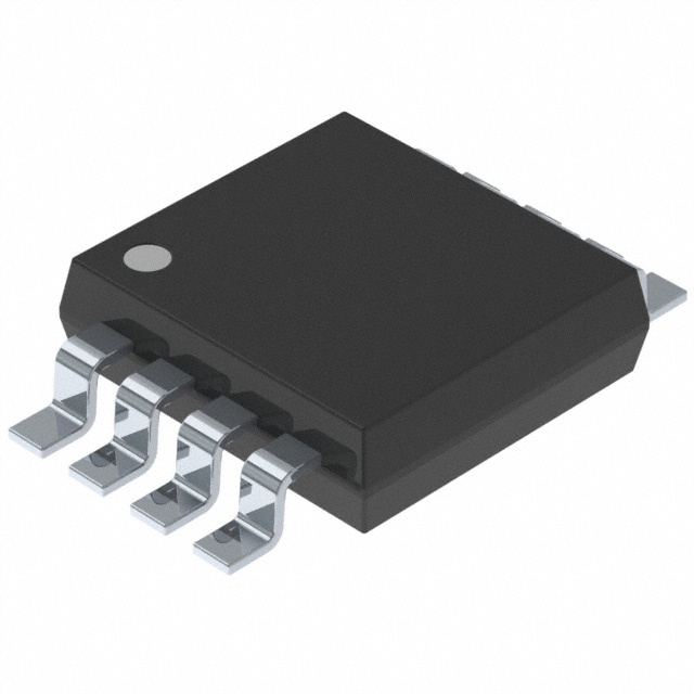
Diodes Incorporated PI6ULS5V9517BUEX
- Part No.:
- PI6ULS5V9517BUEX
- Manufacturer:
- Diodes Incorporated
- Category:
- Signal Buffers, Repeaters, Splitters
- Package:
- 8-TSSOP, 8-MSOP (0.118", 3.00mm Width)
- Datasheet:
-
 PI6ULS5V9517BUEX.pdf
- Description:
- INTERFACE ULS MSOP-8
- Quantity:
- Payment:

- Shipping:

Inventory:2,995
Please send an inquiry. Send us your inquiry, and we will respond immediately.
Product details
Overview
PI6ULS5V9517BUEX from Diodes Incorporated is a dual-channel, bidirectional I²C/SMBus level-translating repeater IC enabling voltage translation between 0.8 V–5.5 V (Port A) and 2.2 V–5.5 V (Port B), supporting up to 400 kHz clock frequency with lock-up free operation, open-drain I/Os, and 5.5 V-tolerant enable and bus pins. It isolates bus capacitance and extends I²C topology in mixed-voltage embedded systems.
For engineers reviewing the PI6ULS5V9517BUEX datasheet, PI6ULS5V9517BUEX pinout, PI6ULS5V9517BUEX application, or PI6ULS5V9517BUEX equivalent, key selection considerations include port-specific supply ranges, propagation delay asymmetry (A→B vs. B→A), buffered low-level behavior on Port B, EN timing constraints (tSU/tH = 100 ns), and star vs. series topology compatibility.
Technical Context
The PI6ULS5V9517BUEX implements two independent bidirectional level-shifting channels using comparator-based input detection and CMOS output drivers powered solely by VCCB. Port A uses a 0.3×VCCA threshold for low-level detection to support sub-1.0 V logic, while Port B employs a 0.3×VCCB threshold plus hysteresis and a buffered ~0.5 V low output to prevent lock-up during arbitration.
It supports standard-mode and fast-mode I²C, preserves clock stretching and multi-master arbitration across ports, and requires external pull-up resistors-167 Ω (0.8–2.7 V) or 450 Ω (3.0–5.5 V) on Port A, 1.35 kΩ on Port B-with 57 pF load capacitance per side. EN must remain stable during active bus cycles to avoid bus hang.
Key Specifications
| Parameter | Value and Actual Design Meaning |
|---|---|
| Supply Voltage (Port A) | 0.8 V to 5.5 V - enables direct interface with ultra-low-voltage controllers (e.g., 0.8 V I/O domains). |
| Supply Voltage (Port B) | 2.2 V to 5.5 V - compatible with mainstream microcontrollers, PMICs, and sensors operating at ≥2.2 V. |
| Max Clock Frequency | 400 kHz - supports Fast-mode I²C, though system-level speed may be reduced by cumulative propagation delays (e.g., 67–255 ns per direction). |
| ESD Protection | 8000 V HBM - exceeds JEDEC JESD22-A114, ensuring robustness in handling-sensitive manufacturing and field environments. |
| I/O Structure | Open-drain outputs with 5.5 V tolerance on SDA/SCL/EN - eliminates need for external clamping diodes when interfacing with higher-voltage buses. |
| Low-Level Output (Port A) | ≤0.2 V @ 6 mA - provides true ground-referenced low signal, enabling reliable recognition by downstream 0.8 V logic. |
| Low-Level Output (Port B) | ~0.5 V - intentionally elevated to prevent false low detection and ensure lock-up free operation during bus contention. |
Pinout & Package
PI6ULS5V9517BUEX is packaged in an 8-pin MSOP (U) with 0.65 mm pitch, footprint-compatible with industry-standard SOIC-8 but with 30% smaller area and improved thermal performance. The package is RoHS-compliant, halogen-free, and tape-and-reel ready (X suffix).
| Pin | Circuit Role | Design Meaning |
|---|---|---|
| 1 | VCCA | Port A supply reference - powers internal comparators and sets 0.3×VCCA low-threshold; not used for core logic power. |
| 2 | SCLA | Port A serial clock input/output - open-drain, referenced to VCCA, supports 0.8 V–5.5 V logic levels. |
| 3 | SDAA | Port A serial data input/output - identical electrical behavior to SCLA; bidirectional with arbitration preservation. |
| 4 | GND | Common ground reference - required for all internal biasing and noise rejection; must be low-impedance. |
| 5 | EN | Active-HIGH enable - must be held static during I²C transactions; toggling mid-cycle causes bus hang. |
| 6 | SDAB | Port B serial data input/output - open-drain, 5.5 V tolerant, outputs buffered ~0.5 V low for lock-up immunity. |
| 7 | SCLB | Port B serial clock input/output - electrically identical to SDAB; shares same VCCB supply and threshold behavior. |
| 8 | VCCB | Primary power supply - powers all internal logic, drivers, and Port B I/Os; defines 0.3×VCCB input thresholds. |
Key Features
| Feature | Design Value |
|---|---|
| Bidirectional Level Translation | Enables seamless communication between 0.8 V SoCs and 3.3 V/5 V peripherals without protocol modification or software overhead. |
| Lock-Up Free Operation | Port B's buffered ~0.5 V low output prevents metastability during arbitration, eliminating risk of bus deadlock in multi-master systems. |
| Star Topology Support | Multiple PI6ULS5V9517BUEX devices can share a common Port A bus, enabling scalable multi-node I²C expansion without added capacitance. |
| Bus Isolation | Electrically separates Port A and Port B capacitance - allows two 400 pF I²C segments to interconnect, doubling total device count or trace length. |
| Powered-Off High-Z I/Os | All SDA/SCL pins enter high-impedance state when VCCB = 0 V - prevents back-powering or leakage into unpowered subsystems. |
Applications
| Industrial Sensor Hub | Multi-Rail Power Management |
|---|---|
|
Use Scenario: A 0.8 V AI inference MCU communicates with 3.3 V temperature/humidity sensors and 5 V actuator drivers over shared I²C. IC Role / Device Role / Timing Role: Repeater isolates voltage domains and buffers SDA/SCL signals bidirectionally while preserving clock stretching and arbitration. Use Value: Eliminates discrete level-shifters and enables direct integration of heterogeneous voltage nodes without custom firmware or timing compensation. |
Use Scenario: A 1.2 V PMIC monitors and controls multiple 3.3 V and 5 V DC-DC converters via I²C, requiring robust noise immunity and fail-safe isolation. IC Role / Device Role / Timing Role: Acts as a fault-containment barrier - disables Port B via EN during PMIC reset to prevent spurious writes to power rails. Use Value: Prevents bus hang during power sequencing and ensures deterministic startup by decoupling low-voltage control logic from high-voltage power stages. |
| Automotive Body Control Module | Medical Wearable Subsystem |
|
Use Scenario: A 1.8 V body controller interfaces with 5 V lighting drivers and 2.5 V door-lock sensors across long PCB traces (>15 cm) exceeding 400 pF bus capacitance. IC Role / Device Role / Timing Role: Extends I²C reach by splitting capacitance into two 400 pF segments and regenerating SDA/SCL waveforms with controlled rise/fall times. Use Value: Maintains 400 kHz Fast-mode timing integrity despite trace-length-induced RC delays, avoiding fallback to slower Standard-mode. |
Use Scenario: A 0.9 V ultra-low-power health sensor SoC exchanges calibration data with 3.3 V Bluetooth LE radio and 2.8 V display driver over compact flex PCB. IC Role / Device Role / Timing Role: Provides voltage translation while minimizing static current (<500 µA on VCCA) and dynamic switching loss. Use Value: Enables sub-1 V operation without compromising I²C interoperability, extending battery life in energy-constrained wearable designs. |
Equivalent & Alternatives
The following parts are listed as comparable options for similar I²C level-shifting repeater applications.
| Alternative Part | Technical Difference | Application Difference | Selection Advice |
|---|---|---|---|
| TCA9617A | Single-channel, supports 1.65 V–5.5 V on both sides; no buffered low output; lower max frequency (1 MHz but limited by system loading). | Lacks Port A/Port B voltage asymmetry - unsuitable for 0.8 V ↔ 2.2 V translation; better for symmetric 1.8 V ↔ 3.3 V links. | Select when symmetric voltage domains exist and higher bandwidth is needed; avoid when sub-1.0 V logic or lock-up immunity is required. |
| PCA9517A | Legacy single-channel repeater; no level translation - only buffers 3.3 V/5 V buses; lacks VCCA/VCCB separation and ESD rating (4 kV HBM). | Cannot translate below 2.7 V; no support for ultra-low-voltage masters; higher propagation delay (≥300 ns). | Use only in legacy 3.3 V/5 V-only systems where cost is critical and modern ESD/low-voltage requirements are absent. |
Compared with TCA9617A and PCA9517A, PI6ULS5V9517BUEX uniquely supports asymmetric 0.8 V ↔ 2.2 V translation with lock-up immunity, making it the only viable choice for next-generation ultra-low-power MCUs interfacing with legacy peripherals.
Availability
PI6ULS5V9517BUEX is available at Aetrix Electronics and suitable for industrial sensor hubs, automotive body control modules, medical wearable subsystems, and multi-rail power management systems requiring stable component supply, long-term lifecycle assurance, and RoHS-compliant packaging.
Supply support for PI6ULS5V9517BUEX includes scheduled delivery planning, volume procurement assistance, BOM continuity management, traceable sourcing, and lifecycle availability coordination for OEM customers, industrial embedded developers, connected-device designers, and electronics production programs.
Manufacturer
Diodes Incorporated is a global manufacturer of discrete semiconductors and integrated circuits, specializing in high-performance, high-reliability components for power management, signal integrity, and connectivity applications.
The PI6ULS5V9517BUEX belongs to Diodes' Pericom® interface solutions portfolio, engineered specifically to solve mixed-voltage I²C/SMBus interoperability challenges in space-constrained, low-power embedded systems.
FAQ
Can PI6ULS5V9517BUEX operate with VCCA = 0.8 V and VCCB = 2.2 V simultaneously?
Yes. The device is explicitly characterized for this condition: Port A accepts 0.8 V–5.5 V, Port B accepts 2.2 V–5.5 V, and internal comparators use 0.3×VCCA and 0.3×VCCB thresholds. At these voltages, VOL on Port A is ≤0.2 V, ensuring reliable low-level detection by 0.8 V receivers, while Port B's ~0.5 V low remains above its 0.3×2.2 V = 0.66 V threshold - a design feature preventing lock-up.
What happens if EN is toggled during an active I²C transaction?
Toggling EN LOW mid-transaction forces both ports into high-impedance, halting SDA/SCL signaling and causing immediate bus hang - slave devices cannot complete ACK/NACK, and masters time out. The datasheet mandates EN state changes only during full bus idle (both lines HIGH for >1.3 ms). EN must remain HIGH throughout START, data, and STOP sequences to maintain protocol compliance.
Why does Port B output ~0.5 V instead of 0 V for LOW?
This buffered low is intentional: it keeps Port B's output voltage above the 0.3×VCCB input threshold (~0.66 V at 2.2 V), preventing the internal comparator from misinterpreting its own output as a valid low. This avoids positive feedback loops and ensures lock-up free arbitration - a critical differentiator versus basic MOSFET-based translators that lack hysteresis and dynamic threshold control.
Is PI6ULS5V9517BUEX compatible with I²C Fast-mode Plus (1 MHz)?
No. The device is rated for up to 400 kHz maximum clock frequency. While propagation delays (e.g., 67 ns A→B) suggest theoretical headroom, the datasheet explicitly limits operation to Fast-mode due to cumulative timing degradation from transition times (tTHL up to 175 ns), bus capacitance splitting constraints, and guaranteed arbitration preservation - Fast-mode Plus timing margins cannot be assured.
PI6ULS5V9517BUEX Specifications
- Product attributes
- Attribute value
- Manufacturer:
- Diodes Incorporated
- Series:
- -
- Package/Case:
- 8-TSSOP, 8-MSOP (0.118", 3.00mm Width)
- Packaging:
- Tape & Reel (TR)
- Product Status:
- Obsolete
- Type:
- Buffer, ReDriver
- Applications:
- I2C
- Input:
- 2-Wire Bus
- Output:
- 2-Wire Bus
- Data Rate (Max):
- 400kHz
- Number of Channels:
- 2
- Delay Time:
- 169ns
- Signal Conditioning:
- -
- Capacitance - Input:
- -
- Voltage - Supply:
- 0.8V ~ 5.5V
- Current - Supply:
- 500µA
- Operating Temperature:
- -
- Grade:
- -
- Qualification:
- -
- Mounting Type:
- Surface Mount
- Supplier Device Package:
- 8-MSOP
PI6ULS5V9517BUEX FAQ
1.How can I place an order for PI6ULS5V9517BUEX through Aetrix?
Please submit a Request for Quotation (RFQ) for PI6ULS5V9517BUEX on Aetrix. Our sales agent will provide a competitive quotation and guide you through the order confirmation once you accept the terms.
2.Are the price and stock information for PI6ULS5V9517BUEX reliable?
The price and inventory of PI6ULS5V9517BUEX are updated periodically and may fluctuate due to market conditions. Stock and pricing data are typically refreshed every 24 hours. Quotation validity for PI6ULS5V9517BUEX is usually 5 days.
3.What payment methods are accepted for PI6ULS5V9517BUEX?
We accept Wire Transfer, PayPal, Credit Card, Western Union, MoneyGram, and Escrow for PI6ULS5V9517BUEX transactions.
Note: Certain payment methods may incur a processing fee.
4.How is shipping managed for PI6ULS5V9517BUEX?
PI6ULS5V9517BUEX orders can be shipped via leading logistics carriers, including DHL, UPS, FedEx, TNT, or Registered Mail.
Once your PI6ULS5V9517BUEX order is processed, you will receive an email with the shipment details and tracking number.
Note: Tracking information may take up to 24 hours to appear. Express delivery typically takes 3–5 business days.
5.How can I obtain technical support or documentation for PI6ULS5V9517BUEX?
For technical support, including PI6ULS5V9517BUEX datasheets, pinout diagrams, or application guidance, please contact our engineering support team. They can provide detailed documentation and assistance for your PI6ULS5V9517BUEX requirements.
6.How does Aetrix verify that PI6ULS5V9517BUEX is sourced from the original manufacturer or authorized distributors?
All PI6ULS5V9517BUEX products on Aetrix are procured from qualified distributors and authorized channels. Our dedicated quality assurance team conducts strict verification, including traceability checks and, if necessary, third-party testing. This ensures that PI6ULS5V9517BUEX meets industry standards.
7.What is the process for return or replacement of PI6ULS5V9517BUEX?
All PI6ULS5V9517BUEX units undergo pre-shipment inspection (PSI). If there is an issue with PI6ULS5V9517BUEX, returns or replacements are accepted under the following conditions:
1.Quantity discrepancies, incorrect items, or visible external defects (such as breakage or corrosion), acknowledged by Aetrix.
2.The issue is reported within 90 days of delivery.
3.The PI6ULS5V9517BUEX part is unused and in its original packaging.
Return procedure for PI6ULS5V9517BUEX:
1.Submit a request within 90 days.
2.Obtain a Return Material Authorization (RMA) from Aetrix.
PI6ULS5V9517BUEX Tags
-
PCA9509GM,125
NXP USA Inc.

-
PCA9617ADPJ
NXP USA Inc.

-
TCA9509DGKR
Texas Instruments

-
PCA9617ATPZ
NXP USA Inc.
-
PCA9517ADP,118
NXP USA Inc.
-
PCA9515ADP,118
NXP USA Inc.

-
PCA9515AD,118
NXP USA Inc.
-
PCA9517DP,118
NXP USA Inc.

-
TUSB211ARWBR
Texas Instruments
-
PCA9517AD,118
NXP USA Inc.
-
PCA9517ATP,147
NXP USA Inc.

-
P82B96PWR
Texas Instruments
Tech Hub

Jumper cables guide covering safe connection order, red and black clamp placement, final ground connection, cable gauge, length, clamp quality, copper vs CCA cables, jump starter comparison and battery…

LDO regulator guide covering low dropout voltage, power dissipation, thermal design, PSRR, output noise, capacitor stability, adjustable LDO circuits, LDO vs buck converter and datasheet selection chec…

Conditional Access Module guide covering CAM meaning, CI/CI+ interface, smart card authorization, DVB security workflow, TV and set-top box compatibility, internal electronics, ESD protection, connecto…

Guide to electronic component obsolescence covering EOL risk, PCN/PDN notices, last-time buy planning, replacement options, form-fit-function validation, counterfeit risk and BOM lifecycle management.

18650 battery guide covering lithium-ion cell basics, 3.6V/3.7V voltage, 4.2V charging, mAh and Wh capacity, protected cells, chargers, BMS, series-parallel packs, holders, welding and sourcing checks.…

Hall effect sensor guide covering working principle, linear and digital sensors, Arduino circuits, current sensing, speed detection, automotive applications, A3144 examples, signal filtering and datash…

Product Change Notification guide for electronic components, covering PCN meaning, PCN vs PDN/EOL, common change types, risk levels, form-fit-function review, engineering validation, BOM control, LTB/L…

A practical guide to blend door actuators, covering HVAC function, symptoms, location, AC and heater issues, reset and calibration, replacement cost, electrical diagnosis, compatibility checks, and rep…

Engineering guide to Raspberry Pi alternatives, covering chip-level differences, Orange Pi, ROCK, Jetson, Banana Pi, NanoPi, Compute Module, Pico, GPIO, camera, HAT compatibility, and replacement risks…

Engineering guide to dynamic load response testing for high-current buck converters, covering load step setup, slew rate, Vcore undershoot, overshoot, recovery time, probe location, output capacitors a…


