
 My Inquiry
 My Account


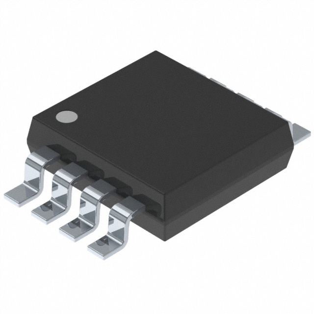
Diodes Incorporated PI6ULS5V9617AUEX
- Part No.:
- PI6ULS5V9617AUEX
- Manufacturer:
- Diodes Incorporated
- Category:
- Signal Buffers, Repeaters, Splitters
- Package:
- 8-TSSOP, 8-MSOP (0.118", 3.00mm Width)
- Datasheet:
-
 PI6ULS5V9617AUEX.pdf
- Description:
- IC BUFFER I2C/SMBUS 8MSOP
- Quantity:
- Payment:

- Shipping:

Inventory:9,496
Please send an inquiry. Send us your inquiry, and we will respond immediately.
Product details
Overview
PI6ULS5V9617AUEX from Diodes Incorporated is a 2-channel bidirectional I²C-bus/SMBus repeater IC with voltage-level translation between 0.6V–5.5V (Port A) and 2.2V–5.5V (Port B), supporting Fast-mode Plus (1 MHz), arbitration, clock stretching, and 540 pF bus capacitance per side at full speed. It isolates bus segments for mixed-voltage systems such as 0.9V microcontrollers interfacing with 3.3V sensors in industrial IoT edge nodes.
For engineers reviewing the PI6ULS5V9617AUEX datasheet, PI6ULS5V9617AUEX pinout, PI6ULS5V9617AUEX application, or PI6ULS5V9617AUEX equivalent, key selection criteria include dual-supply level-shifting capability, open-drain I/O tolerance up to 5.5V, EN pin referenced to VCC(B), propagation delays under 103 ns, and compatibility with PMBus and multi-master SMBus topologies.
Technical Context
The PI6ULS5V9617AUEX implements two independent bidirectional open-drain buffers with asymmetric voltage references: Port A uses dynamic thresholding (0.35×VCC(A)) for sub-1V logic compatibility, while Port B employs static offset buffering (0.55V VOL) to prevent lockup during low-voltage transitions. Its internal power-up sequencing ensures drivers remain disabled until VCC(B) ≥ 2.2V and internal references settle (~400 μs).
It supports star and daisy-chain topologies-multiple Port A buses can be connected in parallel, and series cascading (Port A → Port B) adds only time-of-flight delay without cumulative voltage offset. The EN pin, referenced to VCC(B), must transition only during bus idle states to avoid bus hang or protocol corruption.
Key Specifications
| Parameter | Value and Actual Design Meaning |
|---|---|
| Supply Voltage Range (Port A) | 0.6V to 5.5V - enables direct interface with ultra-low-voltage logic (e.g., 0.8V FPGA I/O, 0.9V MCU cores) |
| Supply Voltage Range (Port B) | 2.2V to 5.5V - compatible with standard 2.5V/3.3V/5V I²C peripherals and SMBus hosts |
| Max Clock Frequency | 1 MHz - supports Fast-mode Plus I²C, doubling bandwidth over legacy Fast-mode (400 kHz) |
| Bus Capacitance Support | 540 pF per side at 1 MHz - allows longer PCB traces or more slave devices without signal integrity loss |
| Propagation Delay (A→B) | 45–102 ns - ensures timing compliance in high-speed multi-drop systems with tight setup/hold margins |
| ESD Robustness | 8000V HBM - protects against handling-induced transients in automated assembly and field-replaceable modules |
| VOL (Port A) | 0.1–0.2 V at 13 mA - guarantees reliable LOW recognition by sub-1V receivers even under heavy load |
Pinout & Package
PI6ULS5V9617AUEX is packaged in an 8-pin MSOP (U) with 0.65 mm pitch, optimized for space-constrained industrial control and portable electronics. Thermal resistance θJA = 180°C/W supports operation up to +85°C ambient without forced airflow.
| Pin/Terminal | Circuit Role | Design Meaning |
|---|---|---|
| VCC(A) | Port A supply reference | Provides bias for Port A input comparators (0.35×VCC(A) threshold); not a power rail for logic - all I/O powered from VCC(B) |
| SCLA | Port A serial clock I/O | Open-drain, 5.5V-tolerant; driven low by internal buffer when SCLB falls below 0.4V |
| SDAA | Port A serial data I/O | Open-drain, 5.5V-tolerant; mirrors SDAB state with sub-100 ns delay and near-0V VOL |
| GND | Common ground reference | Required return path for both ports; no separate analog/digital GND - single-point grounding suffices |
| EN | Active-HIGH enable input | Referenced to VCC(B); internal pull-up holds active unless externally pulled low; must change only during bus idle |
| SDAB | Port B serial data I/O | Open-drain, 5.5V-tolerant; features buffered LOW (~0.55V) to prevent false release detection in cascaded configs |
| SCLB | Port B serial clock I/O | Open-drain, 5.5V-tolerant; same buffered LOW behavior as SDAB; enables clock stretching transparency |
| VCC(B) | Main supply and logic reference | Powers all internal logic, drivers, and EN comparator; defines VIH/VIL thresholds for EN and Port B I/O |
Key Features
| Feature | Design Value |
|---|---|
| Latching-free bidirectional translation | Eliminates bus lockup during simultaneous SDA/SCL transitions by decoupling Port A and Port B driver enable logic |
| Powered-off high-impedance I/O | All pins float to >10 MΩ when VCC(A) = VCC(B) = 0V - prevents back-powering or leakage into unpowered subsystems |
| Dynamic threshold adaptation (Port A) | Input threshold scales with VCC(A) (0.35×VCC(A)), maintaining noise margin across 0.6V–5.5V supply range |
| Static offset buffering (Port B) | Internal 0.55V VOL prevents misinterpretation of weak LOWs in cascaded repeaters - avoids false bus release |
| Multi-topology support | Enables star (Port A parallel) and series (Port A→Port B) configurations without voltage stacking or timing drift |
Applications
| Industrial Sensor Hub | Automotive Body Control Module |
|---|---|
|
Use Scenario: A 0.8V ARM Cortex-M0+ MCU interfaces with multiple 3.3V temperature, humidity, and pressure sensors across 15 cm PCB traces. IC Role / Device Role / Timing Role: Bidirectional I²C repeater with level translation and capacitance isolation - extends bus reach while preserving Fast-mode Plus timing. Use Value: Enables 540 pF total bus load at 1 MHz, eliminating need for external bus buffers or trace-length derating. |
Use Scenario: Central body controller (3.3V) communicates with door module ECUs (1.2V) and seat position sensors (0.9V) via shared SMBus. IC Role / Device Role / Timing Role: Voltage-level translator and bus segment isolator - prevents ground bounce coupling and ensures arbitration integrity across domains. Use Value: Supports clock stretching and multi-master arbitration without protocol corruption, even during partial power-down sequences. |
| Medical Wearable Data Aggregator | Server Baseboard Management Controller (BMC) |
|
Use Scenario: Ultra-low-power 0.6V biosensor SoC streams data to a 2.5V BLE radio via I²C, sharing bus with 1.8V memory. IC Role / Device Role / Timing Role: Sub-1V compatible repeater with powered-off isolation - maintains system sleep current <1 μA when inactive. Use Value: ICC(A) ≤ 8 μA at 0.95V enables battery life extension in always-on health monitors. |
Use Scenario: BMC (3.3V) manages hot-swap FRUs (5V PMBus power supplies) and DIMM SPD EEPROMs (1.5V) on same I²C bus. IC Role / Device Role / Timing Role: Dual-supply SMBus repeater with 5V-tolerant I/O - eliminates level-shifter discretes and reduces BOM count. Use Value: Single IC replaces discrete MOSFET translators, reducing layout area by 60% and improving ESD robustness (8 kV HBM). |
Equivalent & Alternatives
The following parts are listed as comparable options for similar I²C-bus repeater applications.
| Alternative Part | Technical Difference | Application Difference | Selection Advice |
|---|---|---|---|
| TCA9617A | Single-channel; fixed 1.2V–3.3V/5V translation; no sub-1V support; higher VOL (0.7V) on low-VDD side | Limited to 1.2V+ systems; cannot interface with 0.6V–0.9V logic | Select when only one bus segment and ≥1.2V logic are used - lower cost but no ultra-low-VDD capability |
| PCA9517A | Legacy 2-channel repeater; max 400 kHz; no Fast-mode Plus support; 1.65V–5.5V only; no sub-1V operation | Not suitable for 1 MHz designs or systems with <1.2V components | Choose only for backward compatibility in existing 400 kHz SMBus systems - lacks modern timing and voltage flexibility |
Compared with TCA9617A and PCA9517A, PI6ULS5V9617AUEX uniquely supports 0.6V logic, 1 MHz operation, and star-topology expansion - making it the sole option for next-generation ultra-low-power, high-bandwidth I²C interconnects.
Availability
PI6ULS5V9617AUEX is available at Aetrix Electronics and suitable for industrial sensor hubs, automotive body controllers, medical wearables, and server BMCs requiring stable component supply across extended product lifecycles.
Supply support for PI6ULS5V9617AUEX includes scheduled delivery planning, volume procurement assistance, BOM continuity management, traceable sourcing, and lifecycle availability coordination for OEM customers, industrial embedded developers, connected-device designers, and electronics production programs.
Manufacturer
Diodes Incorporated is a global semiconductor company specializing in discrete, analog, and mixed-signal ICs for power management, signal integrity, and connectivity applications.
The PI6ULS5V9617A belongs to Diodes' Pericom® I²C/SMBus repeater family, engineered specifically for voltage-domain bridging in heterogeneous embedded systems where ultra-low-voltage logic coexists with legacy 3.3V/5V peripherals.
FAQ
Can PI6ULS5V9617AUEX operate with VCC(A) = 0.6V and VCC(B) = 2.2V simultaneously?
Yes. The device is fully specified down to 0.6V on Port A and 2.2V on Port B, with guaranteed functionality including 1 MHz operation, 540 pF bus loading, and proper LOW-level translation (VOL ≤ 0.2V on Port A). The 0.4×VCC(A) + 0.8V ≤ VCC(B) constraint is satisfied (0.4×0.6 + 0.8 = 1.04V ≤ 2.2V), ensuring channel enablement and stable comparator operation.
What happens to I²C signals when VCC(B) is unpowered but VCC(A) is active?
All I/O pins enter high-impedance state with leakage <±1 μA, preventing back-powering or signal corruption. Port A pins (SCLA/SDAA) remain 5.5V-tolerant and floating, while Port B pins (SCLB/SDAB) disconnect entirely. No current flows through internal drivers, and EN is inactive - the device behaves as an open circuit, preserving bus integrity in partial-power-down scenarios.
Is PI6ULS5V9617AUEX compatible with PMBus-compliant devices?
Yes. It transparently supports PMBus 1.1/1.2 signaling, including packet error checking (PEC), write-protect commands, and alert response protocols. Its open-drain I/O, arbitration preservation, and clock stretching transparency meet PMBus physical layer requirements. No configuration or external components are needed - it operates as a passive bus extender.
Why does the EN pin reference VCC(B) instead of VCC(A)?
Because all internal logic, drivers, and comparators are powered from VCC(B); referencing EN to VCC(B) ensures consistent threshold behavior regardless of VCC(A) level. This avoids undefined states during power sequencing and guarantees EN activation only when the core logic supply is valid - critical for reliable power-up isolation in mixed-rail systems.
PI6ULS5V9617AUEX Specifications
- Product attributes
- Attribute value
- Manufacturer:
- Diodes Incorporated
- Series:
- -
- Package/Case:
- 8-TSSOP, 8-MSOP (0.118", 3.00mm Width)
- Packaging:
- Tape & Reel (TR)
- Product Status:
- Active
- Type:
- Buffer, ReDriver
- Applications:
- I2C
- Input:
- 2-Wire Bus
- Output:
- 2-Wire Bus
- Data Rate (Max):
- -
- Number of Channels:
- 2
- Delay Time:
- -
- Signal Conditioning:
- -
- Capacitance - Input:
- 7 pF
- Voltage - Supply:
- 0.6V ~ 5.5V
- Current - Supply:
- 50µA
- Operating Temperature:
- -40°C ~ 85°C
- Grade:
- -
- Qualification:
- -
- Mounting Type:
- Surface Mount
- Supplier Device Package:
- 8-MSOP
PI6ULS5V9617AUEX FAQ
1.How can I place an order for PI6ULS5V9617AUEX through Aetrix?
Please submit a Request for Quotation (RFQ) for PI6ULS5V9617AUEX on Aetrix. Our sales agent will provide a competitive quotation and guide you through the order confirmation once you accept the terms.
2.Are the price and stock information for PI6ULS5V9617AUEX reliable?
The price and inventory of PI6ULS5V9617AUEX are updated periodically and may fluctuate due to market conditions. Stock and pricing data are typically refreshed every 24 hours. Quotation validity for PI6ULS5V9617AUEX is usually 5 days.
3.What payment methods are accepted for PI6ULS5V9617AUEX?
We accept Wire Transfer, PayPal, Credit Card, Western Union, MoneyGram, and Escrow for PI6ULS5V9617AUEX transactions.
Note: Certain payment methods may incur a processing fee.
4.How is shipping managed for PI6ULS5V9617AUEX?
PI6ULS5V9617AUEX orders can be shipped via leading logistics carriers, including DHL, UPS, FedEx, TNT, or Registered Mail.
Once your PI6ULS5V9617AUEX order is processed, you will receive an email with the shipment details and tracking number.
Note: Tracking information may take up to 24 hours to appear. Express delivery typically takes 3–5 business days.
5.How can I obtain technical support or documentation for PI6ULS5V9617AUEX?
For technical support, including PI6ULS5V9617AUEX datasheets, pinout diagrams, or application guidance, please contact our engineering support team. They can provide detailed documentation and assistance for your PI6ULS5V9617AUEX requirements.
6.How does Aetrix verify that PI6ULS5V9617AUEX is sourced from the original manufacturer or authorized distributors?
All PI6ULS5V9617AUEX products on Aetrix are procured from qualified distributors and authorized channels. Our dedicated quality assurance team conducts strict verification, including traceability checks and, if necessary, third-party testing. This ensures that PI6ULS5V9617AUEX meets industry standards.
7.What is the process for return or replacement of PI6ULS5V9617AUEX?
All PI6ULS5V9617AUEX units undergo pre-shipment inspection (PSI). If there is an issue with PI6ULS5V9617AUEX, returns or replacements are accepted under the following conditions:
1.Quantity discrepancies, incorrect items, or visible external defects (such as breakage or corrosion), acknowledged by Aetrix.
2.The issue is reported within 90 days of delivery.
3.The PI6ULS5V9617AUEX part is unused and in its original packaging.
Return procedure for PI6ULS5V9617AUEX:
1.Submit a request within 90 days.
2.Obtain a Return Material Authorization (RMA) from Aetrix.
PI6ULS5V9617AUEX Tags
-
PCA9509GM,125
NXP USA Inc.

-
PCA9617ADPJ
NXP USA Inc.

-
TCA9509DGKR
Texas Instruments

-
PCA9617ATPZ
NXP USA Inc.
-
PCA9517ADP,118
NXP USA Inc.
-
PCA9515ADP,118
NXP USA Inc.

-
PCA9515AD,118
NXP USA Inc.
-
PCA9517DP,118
NXP USA Inc.

-
TUSB211ARWBR
Texas Instruments
-
PCA9517AD,118
NXP USA Inc.
-
PCA9517ATP,147
NXP USA Inc.

-
P82B96PWR
Texas Instruments
Tech Hub

Jumper cables guide covering safe connection order, red and black clamp placement, final ground connection, cable gauge, length, clamp quality, copper vs CCA cables, jump starter comparison and battery…

LDO regulator guide covering low dropout voltage, power dissipation, thermal design, PSRR, output noise, capacitor stability, adjustable LDO circuits, LDO vs buck converter and datasheet selection chec…

Conditional Access Module guide covering CAM meaning, CI/CI+ interface, smart card authorization, DVB security workflow, TV and set-top box compatibility, internal electronics, ESD protection, connecto…

Guide to electronic component obsolescence covering EOL risk, PCN/PDN notices, last-time buy planning, replacement options, form-fit-function validation, counterfeit risk and BOM lifecycle management.

18650 battery guide covering lithium-ion cell basics, 3.6V/3.7V voltage, 4.2V charging, mAh and Wh capacity, protected cells, chargers, BMS, series-parallel packs, holders, welding and sourcing checks.…

Hall effect sensor guide covering working principle, linear and digital sensors, Arduino circuits, current sensing, speed detection, automotive applications, A3144 examples, signal filtering and datash…

Product Change Notification guide for electronic components, covering PCN meaning, PCN vs PDN/EOL, common change types, risk levels, form-fit-function review, engineering validation, BOM control, LTB/L…

A practical guide to blend door actuators, covering HVAC function, symptoms, location, AC and heater issues, reset and calibration, replacement cost, electrical diagnosis, compatibility checks, and rep…

Engineering guide to Raspberry Pi alternatives, covering chip-level differences, Orange Pi, ROCK, Jetson, Banana Pi, NanoPi, Compute Module, Pico, GPIO, camera, HAT compatibility, and replacement risks…

Engineering guide to dynamic load response testing for high-current buck converters, covering load step setup, slew rate, Vcore undershoot, overshoot, recovery time, probe location, output capacitors a…


