
 My Inquiry
 My Account


Diodes Incorporated PI7C9X760CZDE
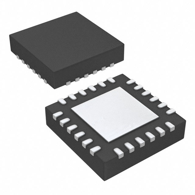
- Part No.:
- PI7C9X760CZDE
- Manufacturer:
- Diodes Incorporated
- Category:
- Controllers
- Package:
- 24-VFQFN Exposed Pad
- Datasheet:
-
 PI7C9X760CZDE.pdf
- Description:
- IC SPI TO UART BRDG 24TQFN 490PC
- Quantity:
- Payment:

- Shipping:

Inventory:2,215
Please send an inquiry. Send us your inquiry, and we will respond immediately.
Product details
Overview
PI7C9X760CZDE from Diodes Incorporated is a single-channel I²C/SPI-to-UART bridge controller with 64-byte TX/RX FIFOs, programmable baud rates up to 16 Mbit/s (4× sampling), hardware/software flow control, and up to eight GPIOs. It supports RS-232/RS-485 interface bridging in industrial automation and embedded battery-powered systems.
For engineers reviewing the PI7C9X760CZDE datasheet, PI7C9X760CZDE pinout, PI7C9X760CZDE application, or PI7C9X760CZDE equivalent, key selection criteria include I²C/SPI host interface compatibility, 64-byte FIFO depth, auto RTS/CTS flow control timing behavior, and GPIO configurability for modem control signals (DSR/DTR/CD/RI).
Technical Context
The PI7C9X760CZDE implements a register-compatible extension of the 16C450 UART architecture with enhanced FIFO management, dual-mode flow control (hardware via RTS/CTS, software via Xon/Xoff), and automatic RS-485 driver direction control triggered by RTS polarity. Its internal baud rate generator supports fractional divisors for precise timing across wide clock inputs (up to 64 MHz).
It operates in either I²C-bus slave mode (fast-mode, 400 kHz) or SPI slave mode (Mode 0, up to 33 Mbps), with interface selection determined by the I2C/SPI pin level. The device integrates IrDA SIR encoding/decoding (115.2 kbps standard, optional 1.152 Mbps) and supports crystal (24 MHz max) or external clock (64 MHz max) timing sources.
Key Specifications
| Parameter | Value and Actual Design Meaning |
|---|---|
| FIFO Depth | 64 bytes per TX/RX buffer - reduces host CPU interrupt load and enables burst data handling without overrun. |
| Max Baud Rate | 16 Mbit/s at 4× oversampling - supports high-speed serial links such as industrial fieldbus or debug interfaces. |
| Interface Modes | I²C fast-mode (400 kHz) or SPI Mode 0 (33 Mbps) - enables flexible host-side integration with microcontrollers lacking native UART peripherals. |
| GPIO Count | 8 programmable I/O pins - configurable as general-purpose I/O or modem control signals (DSR/DTR/CD/RI). |
| Flow Control | Hardware (RTS/CTS auto-handshake) and software (Xon/Xoff, single/dual character) - eliminates data loss in variable-latency systems. |
| Supply Voltage | 1.8 V / 2.5 V / 3.3 V - supports mixed-voltage system designs and low-power battery operation. |
| Package | 24-pin TQFN (4×4 mm, 0.5 mm pitch) - compact footprint suitable for space-constrained portable and embedded modules. |
Pinout & Package
PI7C9X760CZDE is supplied in a 24-pin TQFN package (4×4 mm, 0.5 mm pitch) with exposed thermal pad connected to VSS. Pin functions are shared between I²C and SPI modes via configuration pins (I2C/SPI, CS/A0, SI/A1), and GPIOs support dual-role assignment (e.g., GPIO4/DSR).
| Pin/Terminal | Circuit Role | Design Meaning |
|---|---|---|
| VDD (Pin 4) | Power supply input | Accepts 1.8 V, 2.5 V, or 3.3 V - powers all internal logic and I/O buffers; requires local decoupling. |
| I2C/SPI (Pin 5) | Interface mode select | High = I²C-bus slave; Low = SPI slave - determines pin function mapping for CS/A0, SI/A1, SO, SCL/SCLK, SDA. |
| TX (Pin 23) | UART transmitter output | CMOS-level serial output - drives RS-232/RS-485 transceivers; disabled during loopback mode. |
| RX (Pin 24) | UART receiver input | CMOS-level serial input - accepts asynchronous data; internally looped back during local loopback test. |
| RTS (Pin 21) | Request-to-send control | Active-low open-drain output - controls RS-485 driver direction and enables Auto-RTS flow control when EFR[6] = 1. |
| CTS (Pin 22) | Clear-to-send input | Active-low input - gates UART transmission when Auto-CTS enabled (EFR[7] = 1); status readable via MSR[4]. |
| IRQ (Pin 11) | Interrupt request | Open-drain active-low signal - asserts on RX FIFO trigger, TX FIFO empty, line errors, or GPIO state change. |
| GPIO0–GPIO3 (Pins 12–15) | General-purpose I/O | Configurable as input/output with direction control - usable for status signaling, button sensing, or LED control. |
Key Features
| Feature | Design Value |
|---|---|
| 16C450 register compatibility | Enables drop-in firmware reuse across legacy UART drivers without modification. |
| Programmable FIFO trigger levels | Independent RX/TX interrupt thresholds (via FCR or TLR) optimize host interrupt frequency and latency trade-offs. |
| Auto RS-485 direction control | RTS signal automatically manages half-duplex bus driver enable/disable - eliminates external logic for RS-485 transceivers. |
| IrDA SIR support | Integrated encoder/decoder enables infrared communication at 115.2 kbps (or 1.152 Mbps with optional configuration). |
| Software reset capability | UART core reset via register write - allows runtime recovery without toggling external RESET pin. |
Applications
| Industrial Automation | Embedded Modem Interface |
|---|---|
Use Scenario: Connecting PLCs or HMIs to legacy RS-485 field devices via I²C-enabled microcontrollers. IC Role / Device Role / Timing Role: Protocol bridge converting I²C commands into UART frames with hardware flow control and RS-485 driver direction management. Use Value: Eliminates need for discrete level shifters and direction-control logic while maintaining deterministic timing via programmable FIFO triggers. | Use Scenario: Integrating cellular/GPS modems with low-pin-count MCUs lacking dedicated UART peripherals. IC Role / Device Role / Timing Role: SPI-to-UART bridge providing full modem control (RTS/CTS/DSR/DTR/CD/RI) using GPIOs and hardware flow control. Use Value: Enables complete AT command set execution with reliable handshaking and minimal host CPU overhead via 64-byte FIFOs. |
| Battery-Powered Handheld | Factory Process Monitoring |
Use Scenario: Adding serial debug or sensor telemetry to compact portable instruments powered by coin-cell or Li-ion batteries. IC Role / Device Role / Timing Role: Low-quiescent-current UART bridge supporting 1.8 V operation and software-controlled sleep/wake transitions. Use Value: Reduces system standby current versus discrete MCU + UART solutions while retaining full feature set including IrDA SIR. | Use Scenario: Interfacing temperature, pressure, or flow sensors with RS-232 outputs to an I²C-based data logger. IC Role / Device Role / Timing Role: Isolated protocol translator enabling multi-sensor aggregation over shared I²C bus with independent UART channels. Use Value: Supports simultaneous polling of multiple sensors via configurable GPIOs and error-resilient RX FIFO buffering. |
Equivalent & Alternatives
The following parts are listed as comparable options for similar UART bridge applications.
| Alternative Part | Technical Difference | Application Difference | Selection Advice |
|---|---|---|---|
| SC16IS752IPW | Dual-channel I²C-to-UART with 64-byte FIFOs per channel; no SPI interface; integrated oscillator; smaller 20-pin TSSOP package. | Preferred where dual UARTs are required and space is constrained; lacks RS-485 direction control and IrDA support. | Select when needing two independent UARTs on one I²C bus and lower pin count is critical. |
| MAX3107EEG+ | Single-channel SPI-to-UART only; 128-byte FIFO; higher max baud rate (24 Mbps); no I²C mode or GPIOs beyond basic modem control. | Suitable for high-throughput SPI hosts requiring maximum serial speed; not viable for I²C-based systems or GPIO expansion. | Choose for SPI-only designs demanding >16 Mbps baud rates and deeper FIFO buffering. |
Compared with SC16IS752IPW and MAX3107EEG+, the PI7C9X760CZDE uniquely combines dual-interface flexibility (I²C/SPI), RS-485 direction control, IrDA SIR, and eight GPIOs - making it optimal for mixed-protocol, space-aware industrial edge nodes.
Availability
PI7C9X760CZDE is available at Aetrix Electronics and suitable for industrial automation, embedded modem interfacing, and battery-powered handheld applications requiring stable component supply and long-term manufacturability.
Supply support for PI7C9X760CZDE includes scheduled delivery planning, volume procurement assistance, BOM continuity management, traceable sourcing, and lifecycle availability coordination for OEM customers, industrial embedded developers, connected-device designers, and electronics production programs.
Manufacturer
Diodes Incorporated is a global manufacturer of discrete semiconductors and integrated circuits, specializing in high-performance, energy-efficient components for industrial, computing, and consumer markets.
The PI7C9X760 belongs to Diodes' UART bridge controller product line, designed specifically to simplify serial interface integration in resource-constrained embedded systems with I²C or SPI host buses.
FAQ
What interface protocols does the PI7C9X760CZDE support?
The PI7C9X760CZDE supports both I²C-bus (fast-mode, 400 kHz) and SPI (Mode 0, up to 33 Mbps) as host-side interfaces, selectable via the I2C/SPI pin. It does not support UART-to-UART bridging or USB. Each mode uses distinct pin assignments for clock, data, and chip select/address lines, and register access remains consistent across both interfaces.
How does the PI7C9X760CZDE handle RS-485 half-duplex direction control?
The PI7C9X760CZDE uses the RTS output signal to automatically control RS-485 driver direction: RTS goes low before transmission starts and returns high after the final stop bit. This behavior is enabled via the Enhanced Feature Register (EFR[6]) and requires no external logic. Direction control inversion is also supported through EFR[5], allowing compatibility with inverted-enable transceivers.
Can the GPIO pins be used simultaneously as modem control signals and general-purpose I/O?
No - GPIO4 through GPIO7 are multiplexed: each can operate either as a generic I/O or as a dedicated modem signal (DSR, DTR, CD, RI), but not both concurrently. Configuration is done via the GPIO Control Register (GPIOR[7:4]), and the selected function persists until reprogrammed. GPIO0–GPIO3 remain fully general-purpose with no modem role.
What is the maximum crystal frequency supported for the PI7C9X760CZDE?
The PI7C9X760CZDE supports a maximum crystal frequency of 24 MHz across XTAL1/XTAL2. When using an external clock instead of a crystal, the maximum input frequency rises to 64 MHz. The internal oscillator circuit is only active when a crystal is connected; external clocks bypass the oscillator and feed directly into the timing path.
PI7C9X760CZDE Specifications
- Product attributes
- Attribute value
- Manufacturer:
- Diodes Incorporated
- Package/Case:
- 24-VFQFN Exposed Pad
- Programmable:
- Not Verified
- Protocol:
- I2C
- Function:
- Bridge, I2C/SPI to UART
- Interface:
- UART
- Standards:
- -
- Voltage - Supply:
- 1.62V ~ 3.63V
- Current - Supply:
- -
- Operating Temperature:
- -40°C ~ 85°C
- Supplier Device Package:
- 24-TQFN (4x4)
- Grade:
- -
- Qualification:
- -
PI7C9X760CZDE FAQ
1.How can I place an order for PI7C9X760CZDE through Aetrix?
Please submit a Request for Quotation (RFQ) for PI7C9X760CZDE on Aetrix. Our sales agent will provide a competitive quotation and guide you through the order confirmation once you accept the terms.
2.Are the price and stock information for PI7C9X760CZDE reliable?
The price and inventory of PI7C9X760CZDE are updated periodically and may fluctuate due to market conditions. Stock and pricing data are typically refreshed every 24 hours. Quotation validity for PI7C9X760CZDE is usually 5 days.
3.What payment methods are accepted for PI7C9X760CZDE?
We accept Wire Transfer, PayPal, Credit Card, Western Union, MoneyGram, and Escrow for PI7C9X760CZDE transactions.
Note: Certain payment methods may incur a processing fee.
4.How is shipping managed for PI7C9X760CZDE?
PI7C9X760CZDE orders can be shipped via leading logistics carriers, including DHL, UPS, FedEx, TNT, or Registered Mail.
Once your PI7C9X760CZDE order is processed, you will receive an email with the shipment details and tracking number.
Note: Tracking information may take up to 24 hours to appear. Express delivery typically takes 3–5 business days.
5.How can I obtain technical support or documentation for PI7C9X760CZDE?
For technical support, including PI7C9X760CZDE datasheets, pinout diagrams, or application guidance, please contact our engineering support team. They can provide detailed documentation and assistance for your PI7C9X760CZDE requirements.
6.How does Aetrix verify that PI7C9X760CZDE is sourced from the original manufacturer or authorized distributors?
All PI7C9X760CZDE products on Aetrix are procured from qualified distributors and authorized channels. Our dedicated quality assurance team conducts strict verification, including traceability checks and, if necessary, third-party testing. This ensures that PI7C9X760CZDE meets industry standards.
7.What is the process for return or replacement of PI7C9X760CZDE?
All PI7C9X760CZDE units undergo pre-shipment inspection (PSI). If there is an issue with PI7C9X760CZDE, returns or replacements are accepted under the following conditions:
1.Quantity discrepancies, incorrect items, or visible external defects (such as breakage or corrosion), acknowledged by Aetrix.
2.The issue is reported within 90 days of delivery.
3.The PI7C9X760CZDE part is unused and in its original packaging.
Return procedure for PI7C9X760CZDE:
1.Submit a request within 90 days.
2.Obtain a Return Material Authorization (RMA) from Aetrix.
PI7C9X760CZDE Tags

-
PTN5150AHXMP
NXP USA Inc.

-
USB3740B-AI9-TR
Microchip Technology

-
USB3740B-AI2-TR
Microchip Technology

-
USB3300-EZK-TR
Microchip Technology
-
USB3300-EZK
Microchip Technology

-
FUSB340TMX
onsemi

-
FUSB302BMPX
onsemi

-
DP83826IRHBR
Texas Instruments

-
MCP2518FDT-E/QBB
Microchip Technology
-
FUSB302MPX
onsemi

-
MCP2518FDT-E/SL
Microchip Technology

-
FT260Q-R
FTDI, Future Technology Devices International Ltd
Tech Hub

An engineering guide to LED driver operation, constant-current and constant-voltage outputs, linear and switching topologies, dimming, IC selection, calculations, replacement compatibility, and fault c…

Operational amplifier guide covering op amp basics, feedback, ideal vs real op amps, common configurations, buffer circuits, offset, bias current, gain-bandwidth, slew rate, rail-to-rail limits and sel…

Jumper cables guide covering safe connection order, red and black clamp placement, final ground connection, cable gauge, length, clamp quality, copper vs CCA cables, jump starter comparison and battery…

LDO regulator guide covering low dropout voltage, power dissipation, thermal design, PSRR, output noise, capacitor stability, adjustable LDO circuits, LDO vs buck converter and datasheet selection chec…

Conditional Access Module guide covering CAM meaning, CI/CI+ interface, smart card authorization, DVB security workflow, TV and set-top box compatibility, internal electronics, ESD protection, connecto…

Guide to electronic component obsolescence covering EOL risk, PCN/PDN notices, last-time buy planning, replacement options, form-fit-function validation, counterfeit risk and BOM lifecycle management.

18650 battery guide covering lithium-ion cell basics, 3.6V/3.7V voltage, 4.2V charging, mAh and Wh capacity, protected cells, chargers, BMS, series-parallel packs, holders, welding and sourcing checks.…

Hall effect sensor guide covering working principle, linear and digital sensors, Arduino circuits, current sensing, speed detection, automotive applications, A3144 examples, signal filtering and datash…

Product Change Notification guide for electronic components, covering PCN meaning, PCN vs PDN/EOL, common change types, risk levels, form-fit-function review, engineering validation, BOM control, LTB/L…

A practical guide to blend door actuators, covering HVAC function, symptoms, location, AC and heater issues, reset and calibration, replacement cost, electrical diagnosis, compatibility checks, and rep…


