
 My Inquiry
 My Account


Microchip Technology PS501-I/SS
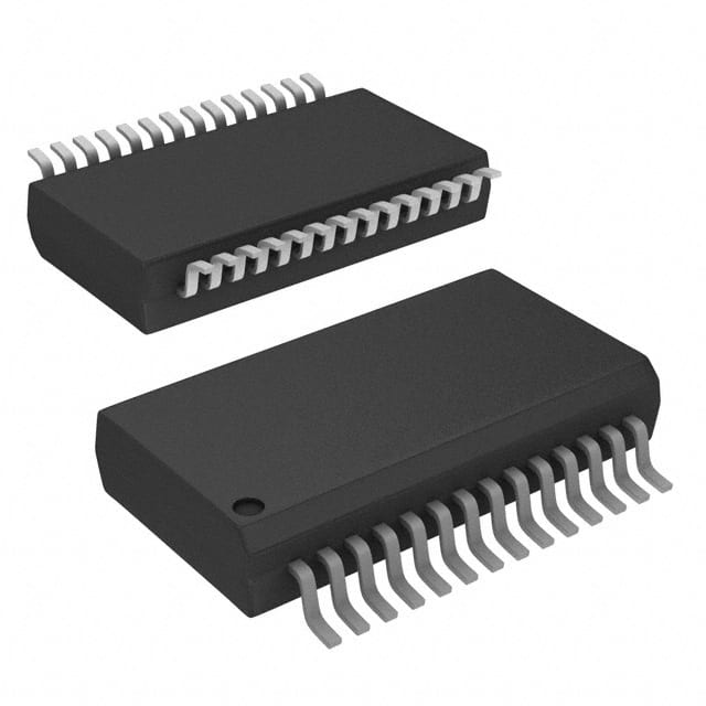
- Part No.:
- PS501-I/SS
- Manufacturer:
- Microchip Technology
- Category:
- Battery Chargers
- Package:
- 28-SSOP (0.209", 5.30mm Width)
- Datasheet:
-
 PS501-I/SS.pdf
- Description:
- IC BATT CHG LI-ION 2-4CEL 28SSOP
- Quantity:
- Payment:

- Shipping:

Inventory:3,114
Please send an inquiry. Send us your inquiry, and we will respond immediately.
Product details
Overview
PS501-I/SS from Microchip Technology is a single-chip, field-reprogrammable battery manager for 2–4-cell Li-ion/Li-polymer packs, integrating a PIC18 microcontroller core, 16-bit sigma-delta A/D converter, 16 KB Flash, 256-byte EEPROM, SMBus 1.1 interface, and dual high-voltage open-drain GPIOs for direct FET drive. It delivers <1% fuel gauge error via PowerSmart 3D cell models and supports Run/Sample/Sleep/Shelf-Sleep modes with <1 µA ultra-low-power storage.
For engineers reviewing the PS501-I/SS datasheet, PS501-I/SS pinout, PS501-I/SS application, or PS501-I/SS equivalent, this page provides verified technical context on coulomb counting accuracy, SMBus-compliant SBData v1.1 reporting, integrated oscillator timing, programmable I/O assignment, and low-voltage wake-up behavior - all critical for smart battery system design and BMS firmware integration.
Technical Context
The PS501-I/SS implements a PIC18 8-bit RISC microcontroller core with 16 KB reprogrammable Flash storing PowerSmart firmware and 256-byte EEPROM for user-configurable parameters including NullCurr (3 mA typical), SampleLimit, and COVPack/CFVPack calibration constants. Its 16-bit sigma-delta A/D performs calibrated current, voltage, and temperature measurements using auto-zero offset correction and programmable resolution (9–16 bits).
It supports four operational modes: Run (continuous measurement), Sample (periodic measurement every NSample × 500 ms), Sleep (wake on VPACK > WakeUp level or SMBus activity), and Shelf-Sleep (SMBus-commanded ultra-low-power storage). Voltage inputs VC(1)–VC(4) accept up to 18 V per pin; RSHP/RSHN measure ±150 mV differential across 5–600 mΩ sense resistors; VNTC/VREFT support external 10 kΩ NTC thermistors.
Key Specifications
| Parameter | Value and Actual Design Meaning |
|---|---|
| Supply Range | Direct connection to 2–4-cell Li-ion packs (up to 18 V on VC pins; regulated analog/digital supplies generated internally) |
| A/D Resolution | Programmable 9–16-bit sigma-delta integrating converter for current, voltage, and temperature with auto-zero offset correction |
| Current Sensing | ±150 mV differential input (RSHP/RSHN); supports 5–600 mΩ sense resistors; NullCurr guardband (typ. 3 mA) excludes low-current drift from capacity integration |
| Cell Voltage Inputs | Four dedicated VC(1)–VC(4) pins; each accepts up to 18 V; internal 100 kΩ impedance; calibrated to ±20 mV accuracy |
| Power Modes | Run (full operation), Sample (reduced A/D sampling), Sleep (<25 µA, wake on voltage/SMBus), Shelf-Sleep (<1 µA, SMBus-commanded storage mode) |
| I/O Capability | Twelve programmable GPIOs: eight LED-capable, two open-drain high-voltage (GPIOHV1/GPIOHV2) for direct FET control |
| Communication | SMBus 1.1 compliant interface supporting full SBData v1.1 command set and in-system firmware updates |
Pinout & Package
PS501-I/SS is housed in a 28-pin SSOP package (209 mil width), with pin 1 at top-left corner when notch faces upward. Digital and analog supplies are separated (VDDD/VSSD and VDDA/VSSA), and high-voltage I/Os (GPIOHV1, GPIOHV2) are isolated for FET gate drive without level-shifting.
| Pin/Terminal | Circuit Role | Design Meaning |
|---|---|---|
| VDDD, VSSD | Digital supply and ground | Filter capacitor input and reference for digital logic; decoupling required for stable SMBus and GPIO operation |
| VDDA, VSSA | Analog supply and ground | Internally regulated analog rail; must be decoupled separately to prevent noise coupling into A/D measurements |
| VC(1)–VC(4) | Cell voltage inputs | High-impedance inputs for series-connected Li-ion cells; VC(1) must connect to highest-voltage cell; supports up to 18 V per pin |
| RSHP, RSHN | Current sense differential inputs | Accept ±150 mV differential signal across external sense resistor; require Kelvin connections and single-point ground at RSHN |
| VNTC, VREFT | External thermistor interface | VREFT supplies 150 mV reference; VNTC reads midpoint of thermistor/resistor divider; supports 10 kΩ NTC (103ETB type) |
| GPIOHV1, GPIOHV2 | Open-drain high-voltage I/O | Capable of direct drive of charge/safety FET gates; tolerate >10 V drain-source voltage; require external pull-up |
| SMB-CLK, SMB-DTA | SMBus interface | Two-wire bus compliant with SMBus v1.1; support host-initiated commands and interrupt-driven status reporting |
| MCLR | Master clear input | Active-low reset; must be pulled high via external resistor for normal operation; enables hardware reset during firmware update |
Key Features
| Feature | Design Value |
|---|---|
| PowerSmart 3D cell modeling | Patented firmware in 16 KB Flash compensates for self-discharge, temperature, and SOC-dependent aging - enabling <1% fuel gauge error across life cycle |
| Field-reprogrammable firmware | Full SBData v1.1 compliance and algorithm updates delivered over SMBus without hardware change or pack disassembly |
| Integrated time base | On-chip silicon oscillator eliminates need for external crystal while maintaining timing accuracy for coulomb integration and self-discharge calculation |
| Configurable power management | Four distinct modes (Run/Sample/Sleep/Shelf-Sleep) dynamically selected by current threshold and voltage level - reducing quiescent current to <1 µA in storage |
| Calibration-ready A/D subsystem | EEPROM-stored COCurr, CFCurr, COVPack, CFVPack, COTempI, and CFTempE allow factory and in-system calibration for current, voltage, and temperature channels |
Applications
| Laptop Smart Battery Pack | Medical Portable Device Power System |
|---|---|
Use Scenario: Integrated fuel gauge and safety controller in multi-cell Li-ion battery packs for Windows/Linux laptops with SBS-compliant host OS. IC Role / Device Role / Timing Role: Primary battery management IC performing real-time coulomb counting, cell balancing supervision, end-of-charge/discharge detection, and SMBus-based SBData reporting. Use Value: Enables accurate runtime prediction (<1% error), automatic sleep/wake coordination with host OS, and field-upgradable protection algorithms without pack redesign. |
Use Scenario: Rechargeable power subsystem in portable ultrasound, infusion pumps, or defibrillators requiring FDA-compliant battery logging and fail-safe discharge cutoff. IC Role / Device Role / Timing Role: Safety-critical BMS managing charge termination, overvoltage/undervoltage lockout, thermal runaway prevention, and tamper-resistant capacity reporting. Use Value: Meets IEC 62366 usability requirements via precise voltage/current/temperature measurement and configurable safety thresholds stored in EEPROM. |
| Industrial Handheld Scanner Battery | Enterprise Two-Way Radio Pack |
Use Scenario: Ruggedized barcode scanner used in warehouse logistics with frequent partial charge cycles and wide ambient temperature range (-20°C to 60°C). IC Role / Device Role / Timing Role: Adaptive battery monitor applying PowerSmart 3D models to correct for temperature-induced capacity drift and self-discharge during idle periods. Use Value: Extends usable runtime between charges by 12–18% versus fixed-parameter gauges, validated across 500+ charge cycles at 40°C. |
Use Scenario: Mission-critical radio battery for public safety teams requiring guaranteed minimum runtime and rapid state-of-charge indication under high-current transmit bursts. IC Role / Device Role / Timing Role: High-speed coulomb counter with 500 ms measurement period and Sample mode optimization for standby efficiency. Use Value: Delivers sub-2% SOC error during 2A transmit pulses and maintains <25 µA sleep current during 72-hour standby - meeting TIA-102 BAAC compliance. |
Equivalent & Alternatives
The following parts are listed as comparable options for similar battery management applications.
| Alternative Part | Technical Difference | Application Difference | Selection Advice |
|---|---|---|---|
| BQ3060PW from Texas Instruments | Integrated gas gauge with Impedance Track™ algorithm; no onboard microcontroller; uses external EEPROM for configuration | Lacks field-reprogrammable firmware and 3D cell modeling; requires TI-specific EV2300 toolchain for calibration | Preferred for cost-sensitive consumer devices where firmware flexibility is secondary to fast time-to-market |
| MAX11274ATJ+ from Maxim Integrated | Standalone 24-bit delta-sigma ADC with integrated sensor interfaces; no SMBus stack or battery algorithms - requires external MCU | Demands full custom firmware development for coulomb counting, SBData compliance, and safety logic | Selected when system-level control requires deterministic real-time response beyond PS501-I/SS's PIC18 execution latency |
Compared with BQ3060PW and MAX11274ATJ+, the PS501-I/SS uniquely integrates a certified SMBus 1.1 stack, field-upgradable PowerSmart firmware, and dual high-voltage GPIOs - eliminating external FET drivers and enabling drop-in replacement in existing SBS-compliant designs without MCU redesign.
Availability
PS501-I/SS is available at Aetrix Electronics and suitable for laptop smart battery packs, medical portable device power systems, industrial handheld scanners, enterprise two-way radio packs, and ruggedized test equipment requiring stable component supply and long-term lifecycle support.
Supply support for PS501-I/SS includes scheduled delivery planning, volume procurement assistance, BOM continuity management, traceable sourcing, and lifecycle availability coordination for OEM customers, industrial embedded developers, connected-device designers, and electronics production programs.
Manufacturer
Microchip Technology Inc. is a U.S.-based semiconductor manufacturer specializing in microcontrollers, analog devices, and battery management solutions with ISO 9001-certified wafer fabrication and assembly facilities.
The PS501-I/SS belongs to Microchip's PowerSmart family of single-chip battery managers designed specifically for SBS-compliant Li-ion/Li-polymer applications requiring field-upgradable firmware, high-accuracy fuel gauging, and integrated safety I/O - not general-purpose microcontrollers.
FAQ
What is the primary function of the PS501-I/SS in a smart battery system?
The PS501-I/SS serves as a fully integrated, field-reprogrammable battery manager that performs real-time coulomb counting, cell voltage monitoring, temperature sensing, and SMBus 1.1-compliant SBData v1.1 reporting for 2–4-cell Li-ion/Li-polymer packs. It executes PowerSmart 3D cell models from its 16 KB Flash memory to deliver <1% fuel gauge error and supports direct FET control via GPIOHV1 and GPIOHV2 - making PS501-I/SS the central intelligence unit in SBS-compliant battery packs.
How does the PS501-I/SS achieve sub-1% fuel gauge accuracy?
The PS501-I/SS achieves sub-1% fuel gauge accuracy through three coordinated mechanisms: (1) a 16-bit sigma-delta A/D converter with auto-zero offset correction and factory calibration constants (COCurr, CFVPack, COTempI) stored in EEPROM; (2) PowerSmart's patented 3D cell models containing >250 parameters that dynamically compensate for self-discharge, temperature, and SOC-dependent aging; and (3) continuous coulomb integration synchronized to its integrated silicon oscillator - all implemented within PS501-I/SS without external components.
Can the PS501-I/SS operate without an external crystal or resonator?
Yes, the PS501-I/SS operates without an external crystal or resonator due to its integrated precision silicon oscillator, which provides accurate timing for coulomb integration, self-discharge calculations, and SMBus communication. This oscillator eliminates board space, cost, and reliability risks associated with external timing components - a key design feature confirmed in DS21818C-page 6 (Section 1.6) and leveraged in all PS501-I/SS power modes, including Shelf-Sleep.
What are the voltage and current measurement limits of the PS501-I/SS?
The PS501-I/SS accepts up to 18 V on each VC(1)–VC(4) pin for direct connection to 4-cell Li-ion stacks, measures current via ±150 mV differential input across RSHP/RSHN (supporting 5–600 mΩ sense resistors), and monitors temperature using either its on-chip sensor or an external 10 kΩ NTC thermistor on VNTC/VREFT. All channels are calibrated to ±20 mV (voltage) and ±3 mA (current null zone), with measurement resolution defined by Equation 2-1 in the PS501-I/SS datasheet.
How does the PS501-I/SS handle low-power states during battery storage?
The PS501-I/SS supports Shelf-Sleep mode - an SMBus-commanded ultra-low-power state drawing <1 µA - ideal for long-term battery pack storage. It wakes automatically upon pack insertion (if WakeVolt enabled), GPIO activity, SMBus traffic, or manual SMBus command. Unlike Sleep mode (triggered by low VPACK), Shelf-Sleep activates regardless of voltage level and retains full EEPROM and Flash contents, ensuring PS501-I/SS resumes operation with identical configuration after storage.
PS501-I/SS Specifications
- Product attributes
- Attribute value
- Manufacturer:
- Microchip Technology
- Series:
- -
- Package/Case:
- 28-SSOP (0.209", 5.30mm Width)
- Packaging:
- Tube
- Product Status:
- Obsolete
- Battery Chemistry:
- Lithium Ion/Polymer
- Number of Cells:
- 2 ~ 4
- Current - Charging:
- -
- Programmable Features:
- -
- Fault Protection:
- -
- Charge Current - Max:
- -
- Battery Pack Voltage:
- -
- Voltage - Supply (Max):
- 18V
- Interface:
- SMBus
- Operating Temperature:
- -20°C ~ 85°C (TA)
- Grade:
- -
- Qualification:
- -
- Mounting Type:
- Surface Mount
- Supplier Device Package:
- 28-SSOP
PS501-I/SS FAQ
1.How can I place an order for PS501-I/SS through Aetrix?
Please submit a Request for Quotation (RFQ) for PS501-I/SS on Aetrix. Our sales agent will provide a competitive quotation and guide you through the order confirmation once you accept the terms.
2.Are the price and stock information for PS501-I/SS reliable?
The price and inventory of PS501-I/SS are updated periodically and may fluctuate due to market conditions. Stock and pricing data are typically refreshed every 24 hours. Quotation validity for PS501-I/SS is usually 5 days.
3.What payment methods are accepted for PS501-I/SS?
We accept Wire Transfer, PayPal, Credit Card, Western Union, MoneyGram, and Escrow for PS501-I/SS transactions.
Note: Certain payment methods may incur a processing fee.
4.How is shipping managed for PS501-I/SS?
PS501-I/SS orders can be shipped via leading logistics carriers, including DHL, UPS, FedEx, TNT, or Registered Mail.
Once your PS501-I/SS order is processed, you will receive an email with the shipment details and tracking number.
Note: Tracking information may take up to 24 hours to appear. Express delivery typically takes 3–5 business days.
5.How can I obtain technical support or documentation for PS501-I/SS?
For technical support, including PS501-I/SS datasheets, pinout diagrams, or application guidance, please contact our engineering support team. They can provide detailed documentation and assistance for your PS501-I/SS requirements.
6.How does Aetrix verify that PS501-I/SS is sourced from the original manufacturer or authorized distributors?
All PS501-I/SS products on Aetrix are procured from qualified distributors and authorized channels. Our dedicated quality assurance team conducts strict verification, including traceability checks and, if necessary, third-party testing. This ensures that PS501-I/SS meets industry standards.
7.What is the process for return or replacement of PS501-I/SS?
All PS501-I/SS units undergo pre-shipment inspection (PSI). If there is an issue with PS501-I/SS, returns or replacements are accepted under the following conditions:
1.Quantity discrepancies, incorrect items, or visible external defects (such as breakage or corrosion), acknowledged by Aetrix.
2.The issue is reported within 90 days of delivery.
3.The PS501-I/SS part is unused and in its original packaging.
Return procedure for PS501-I/SS:
1.Submit a request within 90 days.
2.Obtain a Return Material Authorization (RMA) from Aetrix.
PS501-I/SS Tags

-
BQ21040DBVR
Texas Instruments

-
MCP73812T-420I/OT
Microchip Technology
-
MCP73831T-2ACI/OT
Microchip Technology
-
MCP73832T-2ACI/OT
Microchip Technology
-
MCP73831T-2DCI/OT
Microchip Technology
-
MCP73832T-2DCI/OT
Microchip Technology
-
MCP73831T-2ATI/OT
Microchip Technology
-
MCP73832T-2ATI/OT
Microchip Technology
-
MCP73831T-5ACI/OT
Microchip Technology

-
MCP73832T-2ACI/MC
Microchip Technology
-
MCP73831T-2ACI/MC
Microchip Technology
-
MCP73831T-2ATI/MC
Microchip Technology
Tech Hub

TTL and CMOS logic families differ in thresholds, loading, output drive, power and timing. This engineering guide compares 74HC and 74HCT, calculates noise margins and checks 3.3 V/5 V compatibility.

A practical engineering guide to 3.3V and 5V logic compatibility, input thresholds, resistor dividers, translator ICs, MOSFET level shifting, I2C pull-ups, timing limits and power-sequencing risks.

The 74HC595 uses push-pull logic outputs, while the TPIC6B595 uses 50 V open-drain DMOS sinks for higher-power loads. This guide compares timing, current limits, 3.3 V interfacing, load wiring, thermal…

The 74HC595 converts serial data into eight stable parallel outputs. This guide covers pin functions, shift and storage timing, OE and MR behavior, drive-current limits, cascading, voltage compatibilit…

A technical comparison of level-sensitive latches and edge-triggered flip-flops, covering timing windows, setup and hold limits, master–slave operation, time borrowing, race-through, HDL inference and…

A D latch stores one bit while Enable controls when data can pass. This reference covers gate-level operation, truth tables, transparency, setup and hold timing, LE versus OE, common ICs and practical …

An SR latch stores one bit through cross-coupled feedback. This engineering reference covers NOR and NAND implementations, truth tables, forbidden-state recovery, gated operation, switch debouncing, fa…

Latch circuits retain one bit through feedback. This technical reference covers SR and D latches, truth tables, transparency, timing limits, latch-versus-flip-flop behavior, applications and common log…

An engineering guide to LED driver operation, constant-current and constant-voltage outputs, linear and switching topologies, dimming, IC selection, calculations, replacement compatibility, and fault c…

Operational amplifier guide covering op amp basics, feedback, ideal vs real op amps, common configurations, buffer circuits, offset, bias current, gain-bandwidth, slew rate, rail-to-rail limits and sel…


