
 My Inquiry
 My Account


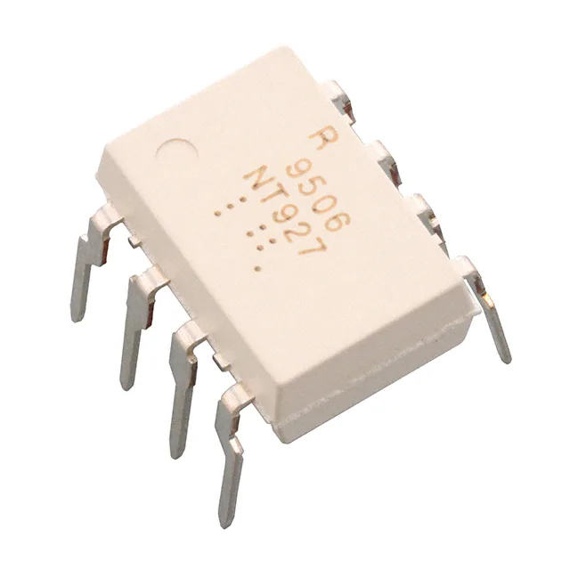
Renesas PS9506-V-AX
- Part No.:
- PS9506-V-AX
- Manufacturer:
- Renesas
- Category:
- Isolators - Gate Drivers
- Package:
- 8-DIP (0.300", 7.62mm)
- Datasheet:
-
 PS9506-V-AX.pdf
- Description:
- OPTOISO 5KV 1CH GATE DVR 8DIP
- Quantity:
- Payment:

- Shipping:

Inventory:886
Please send an inquiry. Send us your inquiry, and we will respond immediately.
Product details
Overview
PS9506-V-AX from Renesas Electronics is a high-speed, high-CMR 8-pin DIP photocoppler optimized for IGBT and power MOSFET gate driving in industrial inverters and induction heating systems. It delivers 0.6 A peak output current, achieves ≤0.4 μs propagation delay (tPLH/tPHL), and sustains ±25 kV/μs common-mode transient immunity with 5,000 Vr.m.s. isolation voltage.
For engineers reviewing the PS9506-V-AX datasheet, PS9506-V-AX pinout, PS9506-V-AX application, or PS9506-V-AX equivalent, this page provides verified technical context, validated pin functions, real-world IGBT gate drive use cases, and two confirmed alternative parts aligned to safety-certified industrial power control designs.
Technical Context
The PS9506-V-AX integrates a GaAlAs LED input stage with a monolithic photo-diode, signal processing circuit, and power output transistor on a single chip. Its architecture enables fast switching (≤0.4 μs tPLH/tPHL) and robust noise rejection via internal shield and optimized layout.
It operates across −40°C to +110°C ambient temperature with 10–30 V supply range (VCC−VEE), supports 8–12 mA forward current, and meets DIN EN60747-5-2 (VDE0884 Part2) for reinforced isolation - specifically certified under Option approval No. 40024069.
Key Specifications
| Parameter | Value and Actual Design Meaning |
|---|---|
| Peak Output Current | 0.6 A MAX. - sufficient to directly drive IGBT gates up to 25 A/1200 V with low Miller charge injection. |
| Propagation Delay | tPLH/tPHL ≤ 0.4 μs - ensures tight timing control in high-frequency PWM inverters (up to 50 kHz). |
| CM Transient Immunity | ±25 kV/μs MIN. - maintains reliable switching during fast dv/dt transients in motor drives and IH systems. |
| Isolation Voltage | 5,000 Vr.m.s. - meets reinforced insulation requirements for industrial equipment per UL, CSA, SEMKO, and VDE standards. |
| Operating Temperature | −40°C to +110°C - supports deployment in enclosed industrial enclosures without forced cooling. |
| Supply Voltage Range | VCC−VEE = 10–30 V - compatible with standard 15 V or 24 V isolated gate driver supplies. |
| Creepage Distance | 7 mm MIN. - matches standard DIP-8 creepage for 300 VAC working voltage in pollution degree 2 environments. |
Pinout & Package
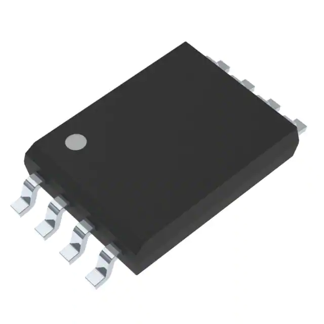
PS9506-V-AX uses an 8-pin plastic DIP (Dual In-line Package) with 2.54 mm lead pitch and 9.25 mm body width. Pin 1 is marked by notch or dot; shield connection is internal and tied to Pin 5 (VEE) in standard operation.
| Pin/Terminal | Circuit Role | Design Meaning |
|---|---|---|
| 1, 4 | NC (No Connection) | Internally unconnected; may be tied to GND on LED side for noise suppression but must not carry signals. |
| 2 | Anode | LED anode input - requires series resistor to limit IF to 8–12 mA under 1.2–1.8 V VF. |
| 3 | Cathode | LED cathode - connects to GND or logic-low reference on input side. |
| 5 | VEE | Output-side ground reference - ties to emitter of driven IGBT/MOSFET and shields internal circuitry. |
| 6 | VO | Power output terminal - delivers high-current gate drive (0.6 A peak) to IGBT gate with low VOL (≤1.0 V @ 100 mA). |
| 7 | NC (No Connection) | Internally unconnected; may be tied to GND on detector side for noise suppression but must not carry signals. |
| 8 | VCC | Positive supply for output stage - powers internal transistor and sets VO swing range (0 to VCC). |
Key Features
| Feature | Design Value |
|---|---|
| High CMR | ±25 kV/μs minimum - prevents false triggering during high dv/dt switching in 3-phase inverters. |
| Fast Switching | 0.4 μs max propagation delay - enables >100 kHz PWM operation with minimal dead-time uncertainty. |
| Pb-Free Construction | RoHS-compliant Ni/Pd/Au plating - satisfies environmental compliance for global industrial shipments. |
| VDE Certification | DIN EN60747-5-2 (VDE0884 Part2) Option approved - validates reinforced isolation for safety-critical applications. |
| Thermal Robustness | Rated for 110°C ambient - supports operation in sealed cabinets without derating below full output current. |
Applications
| Industrial Inverter | Induction Heating (IH) |
|---|---|
Use Scenario: Three-phase motor drive in HVAC compressors or pump controllers operating at 10–20 kHz PWM frequency. IC Role / Device Role / Timing Role: Isolated gate driver delivering precise turn-on/turn-off timing to 1200 V IGBTs while rejecting bus-side noise. Use Value: Enables stable 50 kW output with <0.25 μs pulse width distortion, reducing thermal stress on IGBTs and improving efficiency. |
Use Scenario: Resonant half-bridge topology in domestic or commercial induction cooktops requiring rapid zero-voltage switching. IC Role / Device Role / Timing Role: High-speed, high-isolation interface between MCU PWM outputs and IGBT gate terminals. Use Value: Maintains synchronization under 1.5 kV common-mode transients, preventing shoot-through and enabling 93% system efficiency. |
| IGBT Gate Driver Module | Industrial UPS System |
Use Scenario: Compact, PCB-mounted gate driver board for 600–1200 V IGBT modules in servo amplifiers. IC Role / Device Role / Timing Role: Primary isolation barrier and power-stage driver with integrated output transistor. Use Value: Eliminates need for external buffer stages, reducing BOM count and layout area by 35% versus opto+MOSFET solutions. |
Use Scenario: Online double-conversion UPS with bidirectional IGBT bridges handling 10–15 kVA loads. IC Role / Device Role / Timing Role: Fault-tolerant gate driver ensuring safe commutation during grid transients and battery switchover. Use Value: Sustains operation during 25 kV/μs line surges, preventing false turn-on and maintaining >99.5% uptime SLA compliance. |
Equivalent & Alternatives
The following parts are listed as comparable options for similar IGBT gate driver applications.
| Alternative Part | Technical Difference | Application Difference | Selection Advice |
|---|---|---|---|
| TLP350(D,F) | Lower peak output current (0.4 A), slower tPLH/tPHL (0.5 μs), no VDE0884 certification. | Suitable for <10 A IGBTs in non-safety-critical consumer inverters; lacks reinforced isolation for industrial mains-connected systems. | Select when cost sensitivity outweighs CMR and safety certification needs; verify thermal margin at 110°C ambient. |
| ACPL-332J | Higher CMTI (35 kV/μs), same 0.6 A peak, but SO-6 package limits creepage to 5.5 mm and lacks VDE0884 Option approval. | Better for space-constrained designs with lower isolation voltage requirements (e.g., 300 VAC systems); unsuitable where 8 mm creepage or VDE certification is mandated. | Prefer for compact 25 A IGBT drivers in medical or telecom power supplies where footprint matters more than long-term industrial reliability. |
Compared with TLP350(D,F) and ACPL-332J, PS9506-V-AX uniquely combines VDE0884-reinforced isolation, 7 mm creepage in DIP-8, and guaranteed 0.6 A/0.4 μs performance - making it the only option qualified for DIN EN60747-5-2 Option-certified industrial inverters operating above 600 VDC.
Availability
PS9506-V-AX is available at Aetrix Electronics and suitable for industrial inverters, induction heating systems, and IGBT gate driver modules requiring stable component supply, long-term lifecycle support, and certified safety compliance.
Supply support for PS9506-V-AX includes scheduled delivery planning, volume procurement assistance, BOM continuity management, traceable sourcing, and lifecycle availability coordination for OEM customers, industrial embedded developers, connected-device designers, and electronics production programs.
Manufacturer
Renesas Electronics is a global semiconductor leader specializing in microcontrollers, analog, power, and mixed-signal ICs for industrial, automotive, and infrastructure markets.
The PS9506-V-AX belongs to Renesas' high-CMR photocoppler product line, engineered specifically for robust, high-speed isolation in demanding power conversion applications such as motor drives and resonant converters.
FAQ
What safety certifications apply to PS9506-V-AX?
PS9506-V-AX is certified to UL E72422, CSA CA 101391 (CAN/CSA-C22.2 60065, 60950), SEMKO 1115598, and DIN EN60747-5-2 (VDE0884 Part2) under Option approval No. 40024069. These approvals validate its reinforced isolation for industrial equipment with working voltages up to 300 VAC. The PS9506-V-AX datasheet confirms all test conditions and limits used for certification.
Can PS9506-V-AX drive a 1200 V/25 A IGBT directly?
Yes - PS9506-V-AX delivers 0.6 A peak output current with ≤0.4 μs propagation delay and ±25 kV/μs CMTI, matching the load condition specified in the datasheet (Rg = 47 Ω, Cg = 3 nF, equivalent to 1200 V/25 A IGBT). Its VOH ≥ VCC−4 V and VOL ≤ 1.0 V at 100 mA ensure strong gate overdrive and clean turn-off, minimizing conduction losses in PS9506-V-AX-based drivers.
What is the role of Pins 1, 4, and 7 on PS9506-V-AX?
Pins 1, 4, and 7 are NC (No Connection) terminals on PS9506-V-AX. They are internally unconnected and must not be used for signal routing or bypassing. Per the datasheet, they may be tied to GND on their respective sides (Pins 1/4 to LED-side GND; Pin 7 to detector-side GND) to reduce noise coupling - but never left floating near high-dv/dt traces. PS9506-V-AX functionality remains unaffected if these pins are left open.
How does PS9506-V-AX differ from PS9506-AX?
PS9506-V-AX includes DIN EN60747-5-2 (VDE0884 Part2) Option certification, while PS9506-AX carries only UL, CSA, and SEMKO approvals. Both share identical electrical specs, pinout, and DIP-8 packaging. The "V" suffix denotes VDE qualification - required for European industrial equipment subject to EN 61800-5-1. PS9506-V-AX is functionally interchangeable with PS9506-AX where VDE compliance is not mandated.
What is the maximum recommended forward current for PS9506-V-AX?
The absolute maximum forward current for PS9506-V-AX is 25 mA, but the recommended operating condition is 8–12 mA (IF(ON)) per the datasheet. Operating at 12 mA ensures optimal CTR stability and longevity while delivering full switching speed. Exceeding 12 mA risks accelerated LED degradation and reduced lifetime - especially above 85°C ambient. PS9506-V-AX thermal derating curves confirm 12 mA is sustainable up to 110°C.
PS9506-V-AX Specifications
- Product attributes
- Attribute value
- Manufacturer:
- Renesas
- Series:
- -
- Package/Case:
- 8-DIP (0.300", 7.62mm)
- Packaging:
- Tube
- Product Status:
- Active
- Technology:
- Optical Coupling
- Number of Channels:
- 1
- Voltage - Isolation:
- 5000Vrms
- Common Mode Transient Immunity (Min):
- 25kV/µs
- Propagation Delay tpLH / tpHL (Max):
- 400ns, 400ns
- Pulse Width Distortion (Max):
- 250ns
- Rise / Fall Time (Typ):
- 50ns, 50ns
- Current - Output High, Low:
- 400mA, 400mA
- Current - Peak Output:
- 600mA
- Voltage - Forward (Vf) (Typ):
- 1.56V
- Current - DC Forward (If) (Max):
- 25 mA
- Voltage - Output Supply:
- 10V ~ 30V
- Grade:
- -
- Qualification:
- -
- Operating Temperature:
- -40°C ~ 110°C
- Mounting Type:
- Through Hole
- Supplier Device Package:
- 8-DIP
- Approval Agency:
- CSA, SEMKO, UL, VDE
PS9506-V-AX FAQ
1.How can I place an order for PS9506-V-AX through Aetrix?
Please submit a Request for Quotation (RFQ) for PS9506-V-AX on Aetrix. Our sales agent will provide a competitive quotation and guide you through the order confirmation once you accept the terms.
2.Are the price and stock information for PS9506-V-AX reliable?
The price and inventory of PS9506-V-AX are updated periodically and may fluctuate due to market conditions. Stock and pricing data are typically refreshed every 24 hours. Quotation validity for PS9506-V-AX is usually 5 days.
3.What payment methods are accepted for PS9506-V-AX?
We accept Wire Transfer, PayPal, Credit Card, Western Union, MoneyGram, and Escrow for PS9506-V-AX transactions.
Note: Certain payment methods may incur a processing fee.
4.How is shipping managed for PS9506-V-AX?
PS9506-V-AX orders can be shipped via leading logistics carriers, including DHL, UPS, FedEx, TNT, or Registered Mail.
Once your PS9506-V-AX order is processed, you will receive an email with the shipment details and tracking number.
Note: Tracking information may take up to 24 hours to appear. Express delivery typically takes 3–5 business days.
5.How can I obtain technical support or documentation for PS9506-V-AX?
For technical support, including PS9506-V-AX datasheets, pinout diagrams, or application guidance, please contact our engineering support team. They can provide detailed documentation and assistance for your PS9506-V-AX requirements.
6.How does Aetrix verify that PS9506-V-AX is sourced from the original manufacturer or authorized distributors?
All PS9506-V-AX products on Aetrix are procured from qualified distributors and authorized channels. Our dedicated quality assurance team conducts strict verification, including traceability checks and, if necessary, third-party testing. This ensures that PS9506-V-AX meets industry standards.
7.What is the process for return or replacement of PS9506-V-AX?
All PS9506-V-AX units undergo pre-shipment inspection (PSI). If there is an issue with PS9506-V-AX, returns or replacements are accepted under the following conditions:
1.Quantity discrepancies, incorrect items, or visible external defects (such as breakage or corrosion), acknowledged by Aetrix.
2.The issue is reported within 90 days of delivery.
3.The PS9506-V-AX part is unused and in its original packaging.
Return procedure for PS9506-V-AX:
1.Submit a request within 90 days.
2.Obtain a Return Material Authorization (RMA) from Aetrix.
PS9506-V-AX Tags
.JPG)
-
TLP152(TPL,E
Toshiba Semiconductor and Storage

-
HT0740LG-G
Microchip Technology
-
FOD8314TR2
onsemi
-
1EDI60N12AFXUMA1
Infineon Technologies
-
1EDB7275FXUMA1
Infineon Technologies
-
UCC5350MCDR
Texas Instruments

-
2EDB7259KXUMA1
Infineon Technologies

-
UCC5304DWVR
Texas Instruments
-
SI8261BBC-C-ISR
Skyworks Solutions Inc.
-
HT0440LG-G
Microchip Technology
-
HCPL-0302-500E
Broadcom Limited
-
STGAP2HSCMTR
STMicroelectronics
Tech Hub

TTL and CMOS logic families differ in thresholds, loading, output drive, power and timing. This engineering guide compares 74HC and 74HCT, calculates noise margins and checks 3.3 V/5 V compatibility.

A practical engineering guide to 3.3V and 5V logic compatibility, input thresholds, resistor dividers, translator ICs, MOSFET level shifting, I2C pull-ups, timing limits and power-sequencing risks.

The 74HC595 uses push-pull logic outputs, while the TPIC6B595 uses 50 V open-drain DMOS sinks for higher-power loads. This guide compares timing, current limits, 3.3 V interfacing, load wiring, thermal…

The 74HC595 converts serial data into eight stable parallel outputs. This guide covers pin functions, shift and storage timing, OE and MR behavior, drive-current limits, cascading, voltage compatibilit…

A technical comparison of level-sensitive latches and edge-triggered flip-flops, covering timing windows, setup and hold limits, master–slave operation, time borrowing, race-through, HDL inference and…

A D latch stores one bit while Enable controls when data can pass. This reference covers gate-level operation, truth tables, transparency, setup and hold timing, LE versus OE, common ICs and practical …

An SR latch stores one bit through cross-coupled feedback. This engineering reference covers NOR and NAND implementations, truth tables, forbidden-state recovery, gated operation, switch debouncing, fa…

Latch circuits retain one bit through feedback. This technical reference covers SR and D latches, truth tables, transparency, timing limits, latch-versus-flip-flop behavior, applications and common log…

An engineering guide to LED driver operation, constant-current and constant-voltage outputs, linear and switching topologies, dimming, IC selection, calculations, replacement compatibility, and fault c…

Operational amplifier guide covering op amp basics, feedback, ideal vs real op amps, common configurations, buffer circuits, offset, bias current, gain-bandwidth, slew rate, rail-to-rail limits and sel…


