
 My Inquiry
 My Account


STMicroelectronics PSD813F2VA-20MI
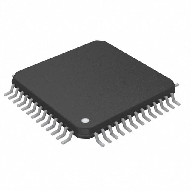
- Part No.:
- PSD813F2VA-20MI
- Manufacturer:
- STMicroelectronics
- Category:
- Specialized ICs
- Package:
- 52-QFP
- Datasheet:
-
 PSD813F2VA-20MI.pdf
- Description:
- IC PROG PERIPH IC 52PQFP
- Quantity:
- Payment:

- Shipping:

Inventory:2,226
Please send an inquiry. Send us your inquiry, and we will respond immediately.
Product details
Overview
PSD813F2VA-20MI from STMicroelectronics is a Flash in-system programmable (ISP) peripheral for 8-bit microcontrollers, integrating dual-bank Flash (1 Mbit primary + 256 Kbit secondary), 256 Kbit SRAM, 27 reconfigurable I/O ports, and a CPLD/DPLD logic block with >3000 gates. It supports concurrent read/erase/write operations and features an internal page register enabling 256× address space expansion - deployed in legacy industrial control systems interfacing with 80C51XA and 68HC11 MCUs.
For engineers reviewing the PSD813F2VA-20MI datasheet, PSD813F2VA-20MI pinout, PSD813F2VA-20MI application, or PSD813F2VA-20MI equivalent, key selection considerations include ISP JTAG support, dual-bank Flash concurrency, PLD-based chip select decoding, and 5 V operation with ECOPACK® TQFP64 packaging.
Technical Context
The PSD813F2VA-20MI implements a tightly coupled memory-peripheral architecture where the primary Flash (32K × 8, 8 uniform sectors) and secondary Flash (64K × 4, 4 uniform sectors) operate independently under JTAG-controlled ISP. Its PLD subsystem comprises 16 output macrocells (OMCs) and 24 input macrocells (IMCs), configurable as CPLD or DPLD for custom address decoding and glue logic replacement.
It interfaces directly with multiplexed and non-multiplexed 8-bit buses (e.g., 80C31, 80C251, 68HC11), using dedicated control signals including Ready/Busy (PC3), Chip Select Input (CSI/PD2), and Turbo Bit for performance scaling. Power management includes Automatic Power-down (APD) and programmable sleep modes with status retention.
Key Specifications
| Parameter | Value and Actual Design Meaning |
|---|---|
| Primary Flash | 1 Mbit (32K × 8, 8 uniform sectors); enables firmware partitioning and background updates without MCU stall. |
| Secondary Flash | 256 Kbit (64K × 4, 4 uniform sectors); used for boot code, configuration tables, or parameter storage. |
| SRAM | 256 Kbit (32K × 8); provides fast, non-volatile-accessible data buffer for real-time MCU tasks. |
| PLD Logic Capacity | >3000 gates; integrates CPLD (16 OMCs + 24 IMCs) and DPLD for user-defined chip select decoding. |
| I/O Ports | 27 reconfigurable pins; 16 support open-drain mode for wired-OR bus interfacing and level translation. |
| Page Register | 8-bit internal register; expands MCU address space by factor of 256, enabling access to full memory map via bank switching. |
| Operating Voltage | 5 V ±10%; compatible with legacy 5 V TTL/CMOS MCU families without level-shifting circuitry. |
| Max Clock Frequency | 20 MHz (–20 suffix); defines maximum bus timing margin for 80C51XA and HC11-compatible interface cycles. |
Pinout & Package
PSD813F2VA-20MI is housed in a 64-pin TQFP (Thin Quad Flat Package) with 0.5 mm pitch, ECOPACK® compliant, and thermally optimized for industrial PCB layouts. Pin assignments follow STMicroelectronics' TQFP64 mechanical specification (Doc ID 7833 Rev 7, Appendix C).
| Pin/Terminal | Circuit Role | Design Meaning |
|---|---|---|
| VCC, GND | Power supply and reference | Dual power domains: VCC powers core logic and I/O; separate GND minimizes noise coupling in mixed-signal MCU systems. |
| PD2 / CSI | Chip Select Input | Active-low enable signal that activates PSD internal decode logic only when asserted - reduces bus contention and dynamic power. |
| PC3 / RDY/BSY | Ready/Busy flag | Open-drain output indicating Flash erase/write progress; allows MCU to poll instead of fixed delay timing. |
| PA0–PA7, PB0–PB7 | Bi-directional I/O ports | Configurable as MCU data/address lines, PLD I/O, or latched address outputs - supports multiplexed bus demultiplexing. |
| PC0–PC7 | JTAG serial interface | Hosts TCK, TMS, TDI, TDO, TRST*; enables full-chip in-system programming and boundary-scan testing without external hardware. |
| PD0–PD7 | General-purpose I/O | 16 pins support open-drain mode; used for interrupt signaling, status flags, or driving LEDs/relays directly. |
Key Features
| Feature | Design Value |
|---|---|
| Concurrent Flash operation | Read from one bank while erasing/writing the other - eliminates MCU idle time during firmware updates. |
| PLD-based address decoding | User-configurable DPLD replaces discrete logic chips (e.g., 74LS138), reducing BOM count and board area in 8-bit systems. |
| JTAG ISP capability | Built-in IEEE 1149.1-compliant port enables low-cost FlashLINK cable programming - simplifies manufacturing test and field upgrades. |
| Programmable power management | Automatic Power-down (APD) unit and PMMR registers allow dynamic current reduction during MCU idle cycles - extends system runtime. |
| Page register expansion | 8-bit register maps 256 pages of memory into 64 KB address space - solves memory limitation in 80C51XA and HC11 derivatives. |
Applications
| Industrial PLC I/O Expansion | Legacy MCU Firmware Upgrade Module |
|---|---|
Use Scenario: Retrofitting aging 80C51XA-based PLC controllers with field-upgradable firmware and expanded I/O mapping. IC Role / Device Role / Timing Role: Acts as memory-mapped peripheral providing Flash storage, SRAM buffer, and PLD-decoded I/O select logic - synchronized to MCU's 20 MHz bus clock. Use Value: Eliminates need for external EPROM sockets and discrete address decoders, reducing failure points and enabling remote firmware patching via JTAG. |
Use Scenario: Adding secure, in-field programmable boot code storage to 68HC11-based automotive body control modules. IC Role / Device Role / Timing Role: Provides protected secondary Flash sector for bootloader and encrypted configuration data - accessed only after hardware reset handshake. Use Value: Enables post-deployment calibration updates and security patches without MCU reprogramming or physical access to the board. |
| Medical Device Data Logger | Point-of-Sale Terminal Memory Subsystem |
Use Scenario: Storing patient waveform history and calibration constants in battery-backed portable ECG units using 80C251 MCU. IC Role / Device Role / Timing Role: Supplies non-volatile Flash + SRAM combo with page register addressing - operates in low-power mode between sampling intervals. Use Value: Maintains data integrity across power cycles while minimizing active current draw via APD-triggered sleep states. |
Use Scenario: Replacing multiple discrete memory and logic ICs in embedded POS terminals based on 80C31 architecture. IC Role / Device Role / Timing Role: Integrates program memory, data RAM, and chip-select logic for display, keypad, and printer interfaces - driven by 12 MHz system clock. Use Value: Reduces component count by ≥7 parts per board, improving MTBF and easing RoHS compliance through single ECOPACK® package. |
Equivalent & Alternatives
The following parts are listed as comparable options for similar Flash-peripheral-with-PLD applications.
| Alternative Part | Technical Difference | Application Difference | Selection Advice |
|---|---|---|---|
| PSD833F2VA-20MI | 2 Mbit primary Flash (vs. 1 Mbit); same SRAM, PLD, and pinout - higher density for larger firmware images. | Required where boot loader + application firmware exceed 1 Mbit; otherwise identical interface and timing behavior. | Select when firmware size exceeds 1 Mbit and board layout cannot accommodate external memory expansion. |
| PSD854F2VA-20MI | Includes Reset signal (RESET) pin and enhanced PLD routing; otherwise identical memory and I/O specs. | Needed in systems requiring hardware reset coordination between MCU and peripheral - not supported in PSD813F2VA-20MI. | Choose only if design mandates synchronous reset assertion to both MCU and PSD during power-on or watchdog timeout. |
Compared with PSD833F2VA-20MI and PSD854F2VA-20MI, the PSD813F2VA-20MI offers optimal cost/performance balance for mid-size firmware deployments where 1 Mbit primary Flash suffices and external reset coordination is handled by MCU-side logic.
Availability
PSD813F2VA-20MI is available at Aetrix Electronics and suitable for industrial PLC retrofitting, legacy medical device data logging, and point-of-sale terminal memory consolidation requiring stable component supply and long-lifecycle support.
Supply support for PSD813F2VA-20MI includes scheduled delivery planning, volume procurement assistance, BOM continuity management, traceable sourcing, and lifecycle availability coordination for OEM customers, industrial embedded developers, connected-device designers, and electronics production programs.
Manufacturer
STMicroelectronics is a global semiconductor leader headquartered in Geneva, Switzerland, designing and manufacturing microcontrollers, analog ICs, power management devices, and memory solutions for industrial, automotive, and consumer markets.
The PSD8XXFX product line was engineered specifically to replace discrete memory, logic, and glue components in 8-bit MCU systems - delivering integrated Flash, SRAM, PLD, and ISP capability in a single ECOPACK® package.
FAQ
Is PSD813F2VA-20MI still in production?
No - PSD813F2VA-20MI is marked obsolete by STMicroelectronics (as confirmed in Doc ID 7833 Rev 7, Table 1). However, Aetrix Electronics maintains verified legacy inventory with full traceability, conforming to original ST specifications and ECOPACK® packaging standards.
What JTAG tools are compatible with PSD813F2VA-20MI?
The device supports standard IEEE 1149.1 JTAG commands and is fully compatible with ST's FlashLINK cable and associated software (PSDsoft v3.x). Third-party JTAG adapters supporting TAP controller emulation (e.g., Segger J-Link with custom SVF scripts) can also be used for programming and debugging.
Can the PLD logic be reconfigured in-system?
Yes - the CPLD and DPLD logic blocks are programmed via JTAG using the same interface used for Flash and SRAM. Configuration bitstreams are stored in dedicated PLD configuration memory and persist across power cycles, enabling field updates without hardware changes.
Does PSD813F2VA-20MI support 3 V operation?
No - PSD813F2VA-20MI is a 5 V-only device (per Table 40, "Operating conditions (5 V devices)" in Doc ID 7833 Rev 7). It is not rated for 3 V operation; attempting to run below 4.5 V may cause timing violations, PLD misconfiguration, or Flash write failures.
PSD813F2VA-20MI Specifications
- Product attributes
- Attribute value
- Manufacturer:
- STMicroelectronics
- Series:
- -
- Package/Case:
- 52-QFP
- Packaging:
- Tray
- Product Status:
- Obsolete
- Programmable:
- Not Verified
- Type:
- Programmable Peripherals IC
- Applications:
- 8-Bit MCU Peripherals
- Mounting Type:
- Surface Mount
- Supplier Device Package:
- 52-PQFP (10x10)
- Grade:
- -
- Qualification:
- -
PSD813F2VA-20MI FAQ
1.How can I place an order for PSD813F2VA-20MI through Aetrix?
Please submit a Request for Quotation (RFQ) for PSD813F2VA-20MI on Aetrix. Our sales agent will provide a competitive quotation and guide you through the order confirmation once you accept the terms.
2.Are the price and stock information for PSD813F2VA-20MI reliable?
The price and inventory of PSD813F2VA-20MI are updated periodically and may fluctuate due to market conditions. Stock and pricing data are typically refreshed every 24 hours. Quotation validity for PSD813F2VA-20MI is usually 5 days.
3.What payment methods are accepted for PSD813F2VA-20MI?
We accept Wire Transfer, PayPal, Credit Card, Western Union, MoneyGram, and Escrow for PSD813F2VA-20MI transactions.
Note: Certain payment methods may incur a processing fee.
4.How is shipping managed for PSD813F2VA-20MI?
PSD813F2VA-20MI orders can be shipped via leading logistics carriers, including DHL, UPS, FedEx, TNT, or Registered Mail.
Once your PSD813F2VA-20MI order is processed, you will receive an email with the shipment details and tracking number.
Note: Tracking information may take up to 24 hours to appear. Express delivery typically takes 3–5 business days.
5.How can I obtain technical support or documentation for PSD813F2VA-20MI?
For technical support, including PSD813F2VA-20MI datasheets, pinout diagrams, or application guidance, please contact our engineering support team. They can provide detailed documentation and assistance for your PSD813F2VA-20MI requirements.
6.How does Aetrix verify that PSD813F2VA-20MI is sourced from the original manufacturer or authorized distributors?
All PSD813F2VA-20MI products on Aetrix are procured from qualified distributors and authorized channels. Our dedicated quality assurance team conducts strict verification, including traceability checks and, if necessary, third-party testing. This ensures that PSD813F2VA-20MI meets industry standards.
7.What is the process for return or replacement of PSD813F2VA-20MI?
All PSD813F2VA-20MI units undergo pre-shipment inspection (PSI). If there is an issue with PSD813F2VA-20MI, returns or replacements are accepted under the following conditions:
1.Quantity discrepancies, incorrect items, or visible external defects (such as breakage or corrosion), acknowledged by Aetrix.
2.The issue is reported within 90 days of delivery.
3.The PSD813F2VA-20MI part is unused and in its original packaging.
Return procedure for PSD813F2VA-20MI:
1.Submit a request within 90 days.
2.Obtain a Return Material Authorization (RMA) from Aetrix.
PSD813F2VA-20MI Tags

-
CAP200DG-TL
Power Integrations
-
ATSHA204A-MAHDA-T
Microchip Technology

-
ATSHA204A-SSHDA-T
Microchip Technology

-
ATSHA204A-STUCZ-T
Microchip Technology
-
ATECC608B-MAHDA-T
Microchip Technology
-
ATECC608B-MAHCZ-S
Microchip Technology

-
ATECC608B-SSHDA-T
Microchip Technology
-
ATECC608B-MAHDA-S
Microchip Technology
-
ATECC608A-MAHDA-S
Microchip Technology
-
ATECC608B-MAVDA-T
Microchip Technology

-
ATECC608A-SSHDA-T
Microchip Technology
-
ATECC508A-MAHDA-T
Microchip Technology
Tech Hub

Operational amplifier guide covering op amp basics, feedback, ideal vs real op amps, common configurations, buffer circuits, offset, bias current, gain-bandwidth, slew rate, rail-to-rail limits and sel…

Jumper cables guide covering safe connection order, red and black clamp placement, final ground connection, cable gauge, length, clamp quality, copper vs CCA cables, jump starter comparison and battery…

LDO regulator guide covering low dropout voltage, power dissipation, thermal design, PSRR, output noise, capacitor stability, adjustable LDO circuits, LDO vs buck converter and datasheet selection chec…

Conditional Access Module guide covering CAM meaning, CI/CI+ interface, smart card authorization, DVB security workflow, TV and set-top box compatibility, internal electronics, ESD protection, connecto…

Guide to electronic component obsolescence covering EOL risk, PCN/PDN notices, last-time buy planning, replacement options, form-fit-function validation, counterfeit risk and BOM lifecycle management.

18650 battery guide covering lithium-ion cell basics, 3.6V/3.7V voltage, 4.2V charging, mAh and Wh capacity, protected cells, chargers, BMS, series-parallel packs, holders, welding and sourcing checks.…

Hall effect sensor guide covering working principle, linear and digital sensors, Arduino circuits, current sensing, speed detection, automotive applications, A3144 examples, signal filtering and datash…

Product Change Notification guide for electronic components, covering PCN meaning, PCN vs PDN/EOL, common change types, risk levels, form-fit-function review, engineering validation, BOM control, LTB/L…

A practical guide to blend door actuators, covering HVAC function, symptoms, location, AC and heater issues, reset and calibration, replacement cost, electrical diagnosis, compatibility checks, and rep…

Engineering guide to Raspberry Pi alternatives, covering chip-level differences, Orange Pi, ROCK, Jetson, Banana Pi, NanoPi, Compute Module, Pico, GPIO, camera, HAT compatibility, and replacement risks…


