
 My Inquiry
 My Account


Diodes Incorporated PT7C43390LEX
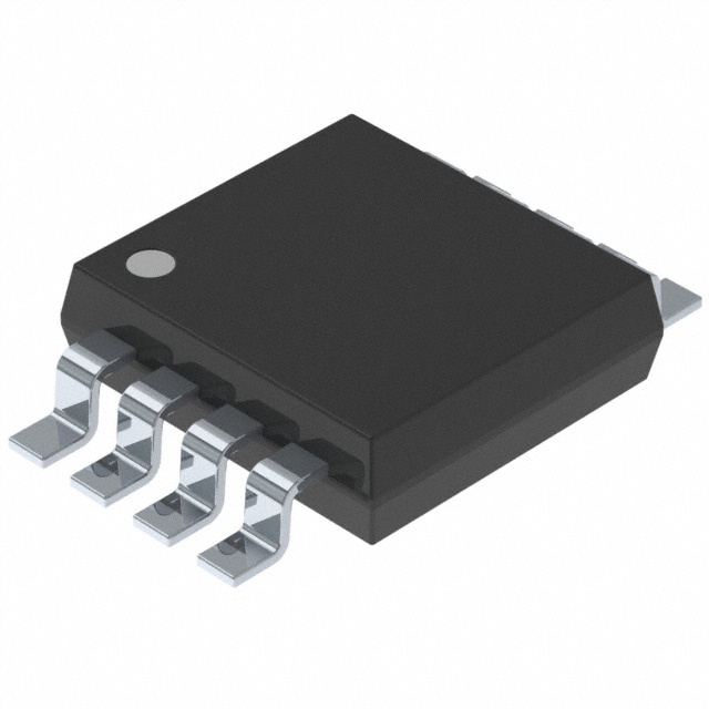
- Part No.:
- PT7C43390LEX
- Manufacturer:
- Diodes Incorporated
- Category:
- Real Time Clocks
- Package:
- 8-TSSOP, 8-MSOP (0.118", 3.00mm Width)
- Datasheet:
-
 PT7C43390LEX.pdf
- Description:
- IC RTC CLK/CALENDAR I2C 8MSOP
- Quantity:
- Payment:

- Shipping:

Inventory:1,943
Please send an inquiry. Send us your inquiry, and we will respond immediately.
Product details
Overview
PT7C43390 from Diodes Incorporated is a CMOS I²C-bus real-time clock IC with auto-calendar support up to year 2099, built-in 32.768 kHz crystal oscillator circuit, and dual interrupt outputs (INT1/INT2). It operates from 1.35 V to 5.5 V, consumes only 0.3 µA typical at 3.0 V, and maintains timekeeping down to 1.25 V - enabling robust backup operation in battery-powered systems such as IP cameras and car navigation units.
For engineers reviewing the PT7C43390 datasheet, PT7C43390 pinout, PT7C43390 application, or PT7C43390 equivalent, key selection criteria include its dual-alarm capability, programmable square-wave output (1 Hz to 32.768 kHz), on-chip clock calibration (±2 ppm achievable), and support for BCD-coded real-time data registers with automatic leap-year calculation.
Technical Context
The PT7C43390 integrates a precision 32.768 kHz oscillator with internal load capacitors (5 pF each), supporting external crystals with CL = 6 pF or 12.5 pF via recommended C1/C2 values. Its clock correction register enables fine-tuning across ±10 ppm IC-to-IC deviation and ±3 ppm voltage-induced drift, allowing temperature-compensated accuracy when paired with an external sensor.
It implements two independent alarm subsystems (Alarm 1/Alarm 2), each configurable via Status Register 2 to trigger INT1 or INT2 with selectable modes: alarm match, periodic minute interrupts, or user-defined frequency output. The I²C interface supports standard (100 kHz) and fast-mode (400 kHz) speeds with NCH open-drain SDA/INT pins requiring external pull-ups.
Key Specifications
| Parameter | Value and Actual Design Meaning |
|---|---|
| Supply Voltage Range | 1.35 V to 5.5 V - supports direct connection to main supply or backup coin cell without level-shifting. |
| Timekeeping Min Voltage | 1.25 V - ensures calendar continuity during brown-out or battery depletion in portable devices. |
| Quiescent Current | 0.3 µA typ. at 3.0 V - extends battery life beyond 10 years on CR2032 (220 mAh) in always-on RTC mode. |
| I²C Interface Speed | Up to 400 kHz - enables fast register access without blocking host MCU during high-frequency polling. |
| Alarm Outputs | Dual open-drain INT1/INT2 - allows simultaneous event signaling (e.g., wake-up + status flag) to separate MCU GPIOs. |
| Square-Wave Output | 1 Hz / 2 Hz / 4 Hz / 8 Hz / 16 Hz / 32.768 kHz - provides flexible timing references for LED blink control or system synchronization. |
| Calendar Range | Year 2000–2099 with auto-leap-year - eliminates firmware date-handling logic for embedded applications. |
Pinout & Package
Available in three RoHS-compliant, lead-free packages: 8-pin SOIC (W), 8-pin TSSOP (L), and 2×3 mm TDFN (ZE). All variants share identical pin functions and electrical behavior.
| Pin/Terminal | Circuit Role | Design Meaning |
|---|---|---|
| 1: INT1 | Open-drain interrupt/output | Configurable alarm 1, periodic interrupt, or 32.768 kHz clock output; requires external pull-up. |
| 2: XOUT | Oscillator output | Drives one terminal of external 32.768 kHz crystal; internal 5 pF capacitor to GND. |
| 3: XIN | Oscillator input | Accepts crystal or external clock; internal 5 pF capacitor to GND; supports 32.768 kHz only. |
| 4: VSS | Ground reference | Primary return path for oscillator, I²C, and logic circuits; must be low-impedance. |
| 5: INT2 | Open-drain interrupt/output | Configurable alarm 2 or user-defined frequency output; independent of INT1 control. |
| 6: SCL | I²C clock input | Master-generated clock; accepts 100 kHz or 400 kHz; CMOS input threshold (0.2VDD/0.8VDD). |
| 7: SDA | I²C bidirectional data | NCH open-drain I/O; requires external pull-up; supports burst-mode register reads/writes. |
| 8: VDD | Positive supply | Single power rail for all functions; powers oscillator, logic, and I/O; supports wide-voltage backup. |
Key Features
| Feature | Design Value |
|---|---|
| Built-in 32.768 kHz oscillator | Eliminates external crystal and load capacitors in cost-sensitive designs; CL = 6 pF optimized. |
| Dual independent alarm system | Enables concurrent wake-up (INT1) and status notification (INT2) without software arbitration. |
| Programmable square-wave output | Provides six fixed frequencies directly from hardware - no MCU timer resource required. |
| Free user register bank | 8-byte SRAM area retains data during VDD dropout; usable as nonvolatile backup memory. |
| Power-on/power-down flag | POC bit in Status Register 1 signals first power application; BLD bit detects undervoltage events. |
| Auto-calendar with leap-year logic | Hardware-calculated date progression avoids firmware bugs in month-end and leap-day transitions. |
Applications
| IP Camera Systems | Car Navigation Units |
|---|---|
|
Use Scenario: Continuous timestamping of video frames and system logs during vehicle ignition cycles and battery disconnects. IC Role / Device Role / Timing Role: Primary real-time clock with battery-backed timekeeping and power-fail detection. Use Value: Maintains accurate UTC timestamps across cold starts using 1.25 V minimum operating voltage and POC/BLD flags. |
Use Scenario: Synchronizing map rendering, traffic updates, and voice guidance with precise local time across varying automotive supply conditions. IC Role / Device Role / Timing Role: Automotive-grade RTC providing stable timebase despite 9–16 V battery fluctuations and engine cranking dips. Use Value: Wide 1.35–5.5 V range and integrated voltage detector enable reliable operation without external supervisors. |
| Smart Energy Meters | DVR/NVR Recording Systems |
|
Use Scenario: Logging energy consumption intervals and tariff switches with tamper-proof time stamps for utility billing compliance. IC Role / Device Role / Timing Role: Tamper-resistant time source with calendar-corrected date tracking and alarm-triggered meter readouts. Use Value: Auto-calendar to 2099 and BCD register format simplify firmware validation for regulatory certification (e.g., ANSI C12.1). |
Use Scenario: Timestamping video segments and triggering motion-based recording with synchronized alarms across multiple camera channels. IC Role / Device Role / Timing Role: Centralized timekeeper generating coordinated INT1/INT2 signals for multi-channel DVR event scheduling. Use Value: Dual interrupt outputs allow independent alarm 1 (motion wake) and alarm 2 (scheduled backup) without MCU intervention. |
Equivalent & Alternatives
The following parts are listed as comparable options for similar real-time clock applications.
| Alternative Part | Technical Difference | Application Difference | Selection Advice |
|---|---|---|---|
| RV-3028-C7 | Lower quiescent current (150 nA), integrated temperature sensor, no built-in oscillator - requires external crystal. | Better suited for ultra-low-power wearables; lacks programmable square-wave output and dual alarms. | Select when >10-year battery life is critical and external crystal layout is acceptable. |
| PCF8563 | Legacy I²C RTC; 0.25 µA typical current; no clock calibration register; max 5.5 V supply; no free registers. | Limited to basic timekeeping; no alarm flexibility or voltage-detection flags. | Choose only for legacy design refresh where feature set reduction is acceptable. |
Compared with RV-3028-C7 and PCF8563, the PT7C43390 uniquely combines built-in oscillator, dual alarms, programmable outputs, and voltage-monitoring flags in a single 8-pin package - making it optimal for space-constrained, feature-rich embedded systems needing autonomous time management.
Availability
PT7C43390 is available at Aetrix Electronics and suitable for IP camera systems, car navigation units, and smart energy meters requiring stable component supply, long-term lifecycle support, and automotive-qualified sourcing options.
Supply support for PT7C43390 includes scheduled delivery planning, volume procurement assistance, BOM continuity management, traceable sourcing, and lifecycle availability coordination for OEM customers, industrial embedded developers, connected-device designers, and electronics production programs.
Manufacturer
Diodes Incorporated is a global semiconductor company specializing in discrete, analog, and mixed-signal solutions for industrial, computing, consumer, and automotive markets.
The PT7C43390 belongs to Diodes' precision timing product line, engineered for high-accuracy, low-power real-time clock applications in battery-backed and automotive environments where reliability and voltage resilience are critical.
FAQ
Does the PT7C43390 require an external crystal?
No - the PT7C43390 integrates a 32.768 kHz crystal oscillator circuit with internal 5 pF load capacitors on XIN and XOUT. An external crystal is optional and only needed if higher stability or custom frequency tolerance is required. When used, CL = 6 pF or 12.5 pF crystals are supported with recommended external C1/C2 values.
How does the clock calibration function improve accuracy?
The PT7C43390 includes a 7-bit clock correction register that adjusts the oscillator's effective frequency by ±10 ppm in 0.95 ppm steps. When calibrated at 25°C using factory-trimmed values or user measurement, total accuracy improves to better than ±2 ppm - sufficient for most industrial and automotive timestamping without external compensation.
Can both INT1 and INT2 pins output the same alarm event?
No - INT1 and INT2 are independently configurable via Status Register 2. Each pin can be assigned to Alarm 1, Alarm 2, periodic interrupt, or programmable square-wave output. Simultaneous identical outputs require external logic; the IC enforces exclusive assignment per pin to prevent signal contention.
What happens to timekeeping during a power transition from main supply to backup battery?
Timekeeping continues uninterrupted if VDD remains ≥1.25 V. The PT7C43390 automatically switches to backup mode, preserves real-time data and alarm settings in BCD registers, and asserts the BLD flag when voltage drops below the detection threshold (1.05 V typ.). No host intervention is required for seamless switchover.
PT7C43390LEX Specifications
- Product attributes
- Attribute value
- Manufacturer:
- Diodes Incorporated
- Series:
- -
- Package/Case:
- 8-TSSOP, 8-MSOP (0.118", 3.00mm Width)
- Packaging:
- Tape & Reel (TR)
- Product Status:
- Active
- Programmable:
- Not Verified
- Type:
- Clock/Calendar
- Features:
- Alarm, Leap Year, Square Wave Output
- Memory Size:
- -
- Time Format:
- HH:MM:SS (12/24 hr)
- Date Format:
- YY-MM-DD-dd
- Interface:
- I2C, 2-Wire Serial
- Voltage - Supply:
- 1.3V ~ 5.5V
- Voltage - Supply, Battery:
- -
- Current - Timekeeping (Max):
- 0.65µA ~ 0.7µA @ 3V ~ 5V
- Operating Temperature:
- -40°C ~ 85°C
- Mounting Type:
- Surface Mount
- Grade:
- -
- Qualification:
- -
- Supplier Device Package:
- 8-MSOP
PT7C43390LEX FAQ
1.How can I place an order for PT7C43390LEX through Aetrix?
Please submit a Request for Quotation (RFQ) for PT7C43390LEX on Aetrix. Our sales agent will provide a competitive quotation and guide you through the order confirmation once you accept the terms.
2.Are the price and stock information for PT7C43390LEX reliable?
The price and inventory of PT7C43390LEX are updated periodically and may fluctuate due to market conditions. Stock and pricing data are typically refreshed every 24 hours. Quotation validity for PT7C43390LEX is usually 5 days.
3.What payment methods are accepted for PT7C43390LEX?
We accept Wire Transfer, PayPal, Credit Card, Western Union, MoneyGram, and Escrow for PT7C43390LEX transactions.
Note: Certain payment methods may incur a processing fee.
4.How is shipping managed for PT7C43390LEX?
PT7C43390LEX orders can be shipped via leading logistics carriers, including DHL, UPS, FedEx, TNT, or Registered Mail.
Once your PT7C43390LEX order is processed, you will receive an email with the shipment details and tracking number.
Note: Tracking information may take up to 24 hours to appear. Express delivery typically takes 3–5 business days.
5.How can I obtain technical support or documentation for PT7C43390LEX?
For technical support, including PT7C43390LEX datasheets, pinout diagrams, or application guidance, please contact our engineering support team. They can provide detailed documentation and assistance for your PT7C43390LEX requirements.
6.How does Aetrix verify that PT7C43390LEX is sourced from the original manufacturer or authorized distributors?
All PT7C43390LEX products on Aetrix are procured from qualified distributors and authorized channels. Our dedicated quality assurance team conducts strict verification, including traceability checks and, if necessary, third-party testing. This ensures that PT7C43390LEX meets industry standards.
7.What is the process for return or replacement of PT7C43390LEX?
All PT7C43390LEX units undergo pre-shipment inspection (PSI). If there is an issue with PT7C43390LEX, returns or replacements are accepted under the following conditions:
1.Quantity discrepancies, incorrect items, or visible external defects (such as breakage or corrosion), acknowledged by Aetrix.
2.The issue is reported within 90 days of delivery.
3.The PT7C43390LEX part is unused and in its original packaging.
Return procedure for PT7C43390LEX:
1.Submit a request within 90 days.
2.Obtain a Return Material Authorization (RMA) from Aetrix.
PT7C43390LEX Tags

-
MCP7940N-I/SN
Microchip Technology

-
MCP7940MT-I/MNY
Microchip Technology

-
PCF85063ATL/1,118
NXP USA Inc.
-
MCP7940NT-I/SN
Microchip Technology

-
MCP7940NT-I/MS
Microchip Technology
-
MCP7940N-I/MS
Microchip Technology

-
PCF85063AT/AY
NXP USA Inc.

-
PCF85063TP/1Z
NXP USA Inc.

-
PCF85063ATT/AJ
NXP USA Inc.
-
MCP7940NT-E/SN
Microchip Technology
-
MCP7940NT-I/MNY
Microchip Technology
-
MCP79400T-I/SN
Microchip Technology
Tech Hub

An engineering guide to LED driver operation, constant-current and constant-voltage outputs, linear and switching topologies, dimming, IC selection, calculations, replacement compatibility, and fault c…

Operational amplifier guide covering op amp basics, feedback, ideal vs real op amps, common configurations, buffer circuits, offset, bias current, gain-bandwidth, slew rate, rail-to-rail limits and sel…

Jumper cables guide covering safe connection order, red and black clamp placement, final ground connection, cable gauge, length, clamp quality, copper vs CCA cables, jump starter comparison and battery…

LDO regulator guide covering low dropout voltage, power dissipation, thermal design, PSRR, output noise, capacitor stability, adjustable LDO circuits, LDO vs buck converter and datasheet selection chec…

Conditional Access Module guide covering CAM meaning, CI/CI+ interface, smart card authorization, DVB security workflow, TV and set-top box compatibility, internal electronics, ESD protection, connecto…

Guide to electronic component obsolescence covering EOL risk, PCN/PDN notices, last-time buy planning, replacement options, form-fit-function validation, counterfeit risk and BOM lifecycle management.

18650 battery guide covering lithium-ion cell basics, 3.6V/3.7V voltage, 4.2V charging, mAh and Wh capacity, protected cells, chargers, BMS, series-parallel packs, holders, welding and sourcing checks.…

Hall effect sensor guide covering working principle, linear and digital sensors, Arduino circuits, current sensing, speed detection, automotive applications, A3144 examples, signal filtering and datash…

Product Change Notification guide for electronic components, covering PCN meaning, PCN vs PDN/EOL, common change types, risk levels, form-fit-function review, engineering validation, BOM control, LTB/L…

A practical guide to blend door actuators, covering HVAC function, symptoms, location, AC and heater issues, reset and calibration, replacement cost, electrical diagnosis, compatibility checks, and rep…


