
 My Inquiry
 My Account


Diodes Incorporated PT7C4563BUEX
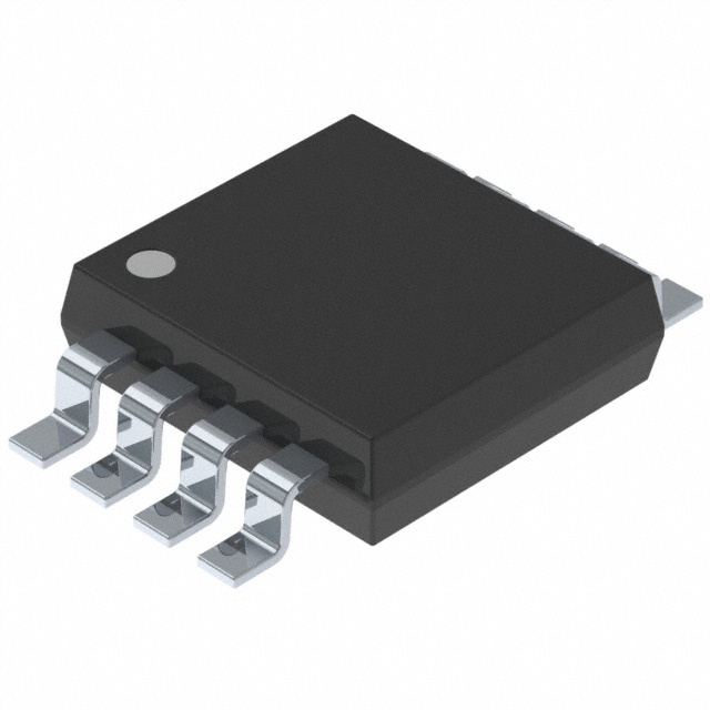
- Part No.:
- PT7C4563BUEX
- Manufacturer:
- Diodes Incorporated
- Category:
- Real Time Clocks
- Package:
- 8-TSSOP, 8-MSOP (0.118", 3.00mm Width)
- Datasheet:
-
 PT7C4563BUEX.pdf
- Description:
- IC RTC I2C SER 8MSOP T&R 2.5K
- Quantity:
- Payment:

- Shipping:

Inventory:2,201
Please send an inquiry. Send us your inquiry, and we will respond immediately.
Product details
Overview
PT7C4563BUEX from Diodes Incorporated is a real-time clock (RTC) IC with I²C interface, 32.768 kHz crystal oscillator, alarm interrupt output, and programmable square-wave output at 1 Hz / 32 Hz / 1.024 kHz / 32.768 kHz. It supports BCD-coded timekeeping (seconds to years), century bit, oscillator fail detection, and operates from 1.3 V to 5.5 V across –40°C to +85°C - used in industrial HMIs, smart meters, and battery-backed embedded controllers.
For engineers reviewing the PT7C4563BUEX datasheet, PT7C4563BUEX pinout, PT7C4563BUEX application, or PT7C4563BUEX equivalent, key selection criteria include I²C timing compliance (up to 400 kHz), low-power operation (≤850 nA at 3.0 V standby), built-in 12 pF load capacitors, open-drain INT/SQW outputs, and alarm register configuration via I²C address 0xA2/A3.
Technical Context
The PT7C4563BUEX implements a fully autonomous RTC function using an internal 32.768 kHz oscillator circuit with built-in 12 pF load capacitance per crystal terminal (CD/CG), eliminating external caps for CL = 12.5 pF crystals. Its I²C slave interface supports standard-mode (100 kHz) and fast-mode (400 kHz) timing with ACK/NACK handshaking and auto-incrementing register addressing.
Timekeeping logic includes a full BCD calendar counter (seconds, minutes, hours, date, month, year, weekday), alarm matching across four registers (minutes/hours/date/weekday), and status flags for oscillator failure (OSF) and alarm flag (AF). The SQW output is independently configurable via RS1/RS0 bits and enabled/disabled via SQWE without affecting RTC operation.
Key Specifications
| Parameter | Value and Actual Design Meaning |
|---|---|
| Interface | I²C bus (7-bit address 0x51), supports 100 kHz / 400 kHz clock rates with standard ACK protocol |
| Supply Voltage | 1.3 V to 5.5 V - enables direct connection to 1.8 V, 3.3 V, or 5 V system rails without level shifters |
| Standby Current | 400–650 nA at 3.0 V (SQW disabled); 600–850 nA (SQW enabled at 32 kHz) - extends coin-cell battery life >10 years |
| Square-Wave Output | Four selectable frequencies: 32.768 kHz / 1.024 kHz / 32 Hz / 1 Hz - usable as system clock source or wake-up signal |
| Oscillator Support | 32.768 kHz crystal with integrated 12 pF CD/CG capacitors - eliminates need for external load caps when using CL = 12.5 pF crystals |
| Alarm Function | Matchable on minutes/hours/date/weekday with independent enable bits (AE) and flag (AF) - triggers open-drain INT pin |
| Operating Temperature | –40°C to +85°C - qualified for industrial-grade embedded applications including metering and automation |
Pinout & Package
PT7C4563BUEX is packaged in an 8-pin MSOP (U package), 3.0 mm × 3.0 mm body, 0.65 mm pitch, with exposed pad for thermal enhancement.
| Pin/Terminal | Circuit Role | Design Meaning |
|---|---|---|
| 1 X1 | Oscillator Input | Crystal terminal connected to internal inverter input; requires 32.768 kHz tuning fork crystal |
| 2 X2 | Oscillator Output | Crystal terminal connected to internal inverter output; forms Pierce oscillator with X1 and built-in 12 pF CG/CD |
| 3 INT | Interrupt Output | Open-drain, active-low alarm/interrupt signal; requires external pull-up resistor (typically 4.7 kΩ) |
| 4 GND | Ground Reference | Primary analog/digital ground return; must be low-impedance and decoupled near VCC pin |
| 5 SDA | I²C Data I/O | Open-drain bidirectional data line; requires external pull-up resistor (shared with other I²C devices) |
| 6 SCL | I²C Clock Input | Input-only clock line synchronized to master; accepts 100/400 kHz waveforms with defined rise/fall times ≤300 ns |
| 7 SQW | Square-Wave Output | Open-drain clock output; frequency selected by RS1/RS0 bits; high-impedance when SQWE = 0 |
| 8 VCC | Power Supply | Single supply input (1.3–5.5 V); bypass with 100 nF ceramic capacitor placed <2 mm from pin |
Key Features
| Feature | Design Value |
|---|---|
| Integrated Crystal Load Capacitance | 12 pF per terminal (CD/CG) - reduces BOM count and PCB layout sensitivity for 12.5 pF crystals |
| Oscillator Fail Detection | OSF bit in seconds register - enables firmware validation of clock integrity after power-up or brownout |
| Alarm Flexibility | Independent enable bits (AE) per alarm register - allows minute-only, hour+date, or weekday-triggered events |
| Low-Power Operation | Sub-µA standby current at 3.0 V - supports >10-year operation on CR2032 coin cell with SQW disabled |
| I²C Address Compatibility | Fixed 7-bit address 0x51 (A2h write / A3h read) - avoids address conflict in multi-peripheral I²C systems |
Applications
| Smart Energy Metering | Industrial HMI Panels |
|---|---|
|
Use Scenario: Battery-backed time stamping of energy consumption logs in DIN-rail mounted electricity meters. IC Role / Device Role / Timing Role: Primary RTC providing accurate wall-clock time, date, and weekday with alarm-triggered data upload initiation. Use Value: Maintains time accuracy within ±2 ppm over –25°C to +70°C using 32.768 kHz crystal; OSF flag ensures log validity after power interruption. |
Use Scenario: Real-time timestamping of operator actions and alarm events in factory-floor HMIs with extended temperature operation. IC Role / Device Role / Timing Role: Standalone timekeeping engine interfaced via I²C to ARM Cortex-M host MCU; supplies timestamps and scheduled wake-up signals. Use Value: Operates reliably from –40°C to +85°C with <850 nA standby current, enabling fanless enclosure designs and long maintenance intervals. |
| POS Terminal Clocking | Networked Building Controllers |
|
Use Scenario: Transaction timestamping and fiscal logging in retail point-of-sale terminals with backup battery support. IC Role / Device Role / Timing Role: Time-of-day source for secure transaction records; alarm interrupt triggers daily report generation. Use Value: BCD-encoded registers simplify firmware parsing; century bit ensures Y2K+ compliance through year 2100. |
Use Scenario: Scheduling of HVAC cycles, lighting control, and sensor polling in IP-connected building automation gateways. IC Role / Device Role / Timing Role: System time base for time-of-day scheduling and periodic wake-up of low-power microcontrollers during idle periods. Use Value: Programmable 1 Hz SQW output serves as precise sleep/wake timer; I²C fast-mode (400 kHz) enables rapid register reads during boot. |
Equivalent & Alternatives
The following parts are listed as comparable options for similar real-time clock applications.
| Alternative Part | Technical Difference | Application Difference | Selection Advice |
|---|---|---|---|
| DS3231M | Integrated TCXO (±2 ppm accuracy), higher supply current (1.5 µA), no built-in load caps | Preferred where ambient temperature varies widely (–40°C to +85°C) and highest time accuracy is critical | Choose DS3231M if absolute time accuracy over temperature is prioritized over ultra-low power or BOM simplification |
| PCF8563 | Lower max I²C speed (100 kHz only), no oscillator fail detect, no century bit, 2.5–5.5 V range | Suitable for cost-sensitive consumer electronics where extended temperature range and diagnostics are secondary | Choose PCF8563 if design targets 100 kHz I²C only and does not require OSF monitoring or year-2100 support |
Compared with DS3231M, PT7C4563BUEX offers lower standby current and integrated load capacitance but lacks temperature compensation; compared with PCF8563, it adds oscillator fail detection, century bit, and 400 kHz I²C support - making it optimal for industrial battery-backed systems requiring reliability and longevity.
Availability
PT7C4563BUEX is available at Aetrix Electronics and suitable for industrial HMIs, smart energy meters, POS terminals, and networked building controllers requiring stable component supply, long-term lifecycle support, and RoHS-compliant packaging.
Supply support for PT7C4563BUEX includes scheduled delivery planning, volume procurement assistance, BOM continuity management, traceable sourcing, and lifecycle availability coordination for OEM customers, industrial embedded developers, connected-device designers, and electronics production programs.
Manufacturer
Diodes Incorporated is a global semiconductor company specializing in discrete, analog, and mixed-signal ICs for power management, signal integrity, and timing applications.
The PT7C4563BUEX belongs to Diodes' precision timing product line, designed specifically for battery-operated industrial and metering applications demanding low power, high reliability, and simplified crystal interface.
FAQ
What is the I²C address of the PT7C4563BUEX?
The PT7C4563BUEX uses a fixed 7-bit I²C slave address of 0x51. Write operations use address 0xA2 (0x51 << 1 | 0), and read operations use 0xA3 (0x51 << 1 | 1). No address pins or configuration bits alter this value - it is hardwired in silicon.
Does the PT7C4563BUEX require external load capacitors for the 32.768 kHz crystal?
No external load capacitors are required when using a 32.768 kHz crystal with 12.5 pF load capacitance, because the device integrates 12 pF capacitors (CD and CG) internally on X1 and X2 pins. For 6 pF crystals, external 0 pF (direct connection) is recommended per Diodes' layout guidance.
How does the oscillator fail detect (OSF) bit function?
The OSF bit (bit 7 of the seconds register, address 0x02) is set to '1' when the oscillator stops or fails to start, indicating loss of timekeeping integrity. Firmware must clear it by writing '0' after verifying crystal operation - persistent OSF indicates physical crystal or solder issue.
Can the SQW output operate independently of the RTC timekeeping function?
Yes. The SQW output is controlled solely by the SQWE bit and RS1/RS0 frequency select bits in register 0x0D. It remains active even if the time counter chain is disabled via control register bits, enabling use as a general-purpose clock source unrelated to calendar functions.
PT7C4563BUEX Specifications
- Product attributes
- Attribute value
- Manufacturer:
- Diodes Incorporated
- Series:
- -
- Package/Case:
- 8-TSSOP, 8-MSOP (0.118", 3.00mm Width)
- Packaging:
- Tape & Reel (TR)
- Product Status:
- Obsolete
- Programmable:
- Not Verified
- Type:
- Clock/Calendar
- Features:
- Alarm, Leap Year, Square Wave Output
- Memory Size:
- -
- Time Format:
- HH:MM:SS (24 hr)
- Date Format:
- YY-MM-DD-dd
- Interface:
- I2C, 2-Wire Serial
- Voltage - Supply:
- 1.3V ~ 5.5V
- Voltage - Supply, Battery:
- -
- Current - Timekeeping (Max):
- 0.65µA ~ 0.85µA @ 3V ~ 5V
- Operating Temperature:
- -40°C ~ 85°C (TA)
- Mounting Type:
- Surface Mount
- Grade:
- -
- Qualification:
- -
- Supplier Device Package:
- 8-MSOP
PT7C4563BUEX FAQ
1.How can I place an order for PT7C4563BUEX through Aetrix?
Please submit a Request for Quotation (RFQ) for PT7C4563BUEX on Aetrix. Our sales agent will provide a competitive quotation and guide you through the order confirmation once you accept the terms.
2.Are the price and stock information for PT7C4563BUEX reliable?
The price and inventory of PT7C4563BUEX are updated periodically and may fluctuate due to market conditions. Stock and pricing data are typically refreshed every 24 hours. Quotation validity for PT7C4563BUEX is usually 5 days.
3.What payment methods are accepted for PT7C4563BUEX?
We accept Wire Transfer, PayPal, Credit Card, Western Union, MoneyGram, and Escrow for PT7C4563BUEX transactions.
Note: Certain payment methods may incur a processing fee.
4.How is shipping managed for PT7C4563BUEX?
PT7C4563BUEX orders can be shipped via leading logistics carriers, including DHL, UPS, FedEx, TNT, or Registered Mail.
Once your PT7C4563BUEX order is processed, you will receive an email with the shipment details and tracking number.
Note: Tracking information may take up to 24 hours to appear. Express delivery typically takes 3–5 business days.
5.How can I obtain technical support or documentation for PT7C4563BUEX?
For technical support, including PT7C4563BUEX datasheets, pinout diagrams, or application guidance, please contact our engineering support team. They can provide detailed documentation and assistance for your PT7C4563BUEX requirements.
6.How does Aetrix verify that PT7C4563BUEX is sourced from the original manufacturer or authorized distributors?
All PT7C4563BUEX products on Aetrix are procured from qualified distributors and authorized channels. Our dedicated quality assurance team conducts strict verification, including traceability checks and, if necessary, third-party testing. This ensures that PT7C4563BUEX meets industry standards.
7.What is the process for return or replacement of PT7C4563BUEX?
All PT7C4563BUEX units undergo pre-shipment inspection (PSI). If there is an issue with PT7C4563BUEX, returns or replacements are accepted under the following conditions:
1.Quantity discrepancies, incorrect items, or visible external defects (such as breakage or corrosion), acknowledged by Aetrix.
2.The issue is reported within 90 days of delivery.
3.The PT7C4563BUEX part is unused and in its original packaging.
Return procedure for PT7C4563BUEX:
1.Submit a request within 90 days.
2.Obtain a Return Material Authorization (RMA) from Aetrix.
PT7C4563BUEX Tags

-
MCP7940N-I/SN
Microchip Technology

-
MCP7940MT-I/MNY
Microchip Technology

-
PCF85063ATL/1,118
NXP USA Inc.
-
MCP7940NT-I/SN
Microchip Technology

-
MCP7940NT-I/MS
Microchip Technology
-
MCP7940N-I/MS
Microchip Technology

-
PCF85063AT/AY
NXP USA Inc.

-
PCF85063TP/1Z
NXP USA Inc.

-
PCF85063ATT/AJ
NXP USA Inc.
-
MCP7940NT-E/SN
Microchip Technology
-
MCP7940NT-I/MNY
Microchip Technology
-
MCP79400T-I/SN
Microchip Technology
Tech Hub

An engineering guide to LED driver operation, constant-current and constant-voltage outputs, linear and switching topologies, dimming, IC selection, calculations, replacement compatibility, and fault c…

Operational amplifier guide covering op amp basics, feedback, ideal vs real op amps, common configurations, buffer circuits, offset, bias current, gain-bandwidth, slew rate, rail-to-rail limits and sel…

Jumper cables guide covering safe connection order, red and black clamp placement, final ground connection, cable gauge, length, clamp quality, copper vs CCA cables, jump starter comparison and battery…

LDO regulator guide covering low dropout voltage, power dissipation, thermal design, PSRR, output noise, capacitor stability, adjustable LDO circuits, LDO vs buck converter and datasheet selection chec…

Conditional Access Module guide covering CAM meaning, CI/CI+ interface, smart card authorization, DVB security workflow, TV and set-top box compatibility, internal electronics, ESD protection, connecto…

Guide to electronic component obsolescence covering EOL risk, PCN/PDN notices, last-time buy planning, replacement options, form-fit-function validation, counterfeit risk and BOM lifecycle management.

18650 battery guide covering lithium-ion cell basics, 3.6V/3.7V voltage, 4.2V charging, mAh and Wh capacity, protected cells, chargers, BMS, series-parallel packs, holders, welding and sourcing checks.…

Hall effect sensor guide covering working principle, linear and digital sensors, Arduino circuits, current sensing, speed detection, automotive applications, A3144 examples, signal filtering and datash…

Product Change Notification guide for electronic components, covering PCN meaning, PCN vs PDN/EOL, common change types, risk levels, form-fit-function review, engineering validation, BOM control, LTB/L…

A practical guide to blend door actuators, covering HVAC function, symptoms, location, AC and heater issues, reset and calibration, replacement cost, electrical diagnosis, compatibility checks, and rep…


