
 My Inquiry
 My Account


Infineon Technologies PTFA260451E V1
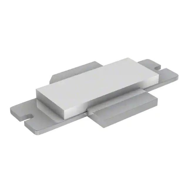
- Part No.:
- PTFA260451E V1
- Manufacturer:
- Infineon Technologies
- Category:
- Single FETs, MOSFETs
- Package:
- 2-Flatpack, Fin Leads
- Datasheet:
-
 PTFA260451E V1.pdf
- Description:
- RF MOSFET LDMOS 28V H-30265-2
- Quantity:
- Payment:

- Shipping:

Inventory:4,256
Please send an inquiry. Send us your inquiry, and we will respond immediately.
Product details
Overview
PTFA260451E from Infineon Technologies is a thermally-enhanced, internally matched 45 W RF LDMOS FET designed for CDMA2000, Super3G, and WiMAX base station power amplifiers operating at 2.62–2.68 GHz. It delivers 10 W average output power with 14 dB gain and –52 dBc ACPR under three-carrier CDMA2000 conditions (28 V, 500 mA, 2680 MHz), and supports 10:1 VSWR tolerance at 45 W CW output.
For engineers reviewing the PTFA260451E datasheet, PTFA260451E pinout, PTFA260451E application, or PTFA260451E equivalent, key selection criteria include drain efficiency (37% typ. @ 45 W PEP), thermal resistance (0.88 °C/W), gate bias stability across temperature, broadband impedance matching (ZIN ≈ 19 Ω, ZOUT ≈ 7 Ω at 2680 MHz), and ESD robustness (HBM Class 2).
Technical Context
This LDMOS transistor employs gold-metallized source/drain interconnects and a thermally enhanced H-30265-2 slotted flange package to maximize junction-to-case heat transfer. Its internal matching network enables operation across the full 2.62–2.68 GHz band without external tuning components in typical base station PA stages.
The device operates with fixed 28 V drain supply and gate bias of 2.5 V (typ.) at 500 mA quiescent current. It exhibits low HCI drift and stable gain (±0.3 dB) over case temperature (–20°C to +85°C), supporting high-linearity multi-carrier modulation schemes including 64-QAM WiMAX and CDMA2000.
Key Specifications
| Parameter | Value and Actual Design Meaning |
|---|---|
| Frequency Range | 2.62–2.68 GHz: Full-band operation for LTE Band 7 / WiMAX 2.6 GHz / CDMA2000 PCS uplink |
| Avg. Output Power (3-Carrier CDMA) | 10 W: Sufficient for multi-carrier macrocell PA stages with 15 dB peak-to-average ratio |
| Drain Efficiency (2-Tone, 45 W PEP) | 37% typ.: Reduces thermal load and DC power draw in 28 V systems |
| ACPR (3-Carrier CDMA) | –52 dBc typ.: Meets 3GPP spectral mask requirements for adjacent channel leakage |
| Thermal Resistance RθJC | 0.88 °C/W: Enables reliable 45 W CW operation with case temperature ≤70°C |
| VSWR Tolerance | 10:1 @ 28 V, 45 W CW: Survives antenna mismatch events without damage or gain collapse |
| ESD Rating | HBM Class 2 (≥2 kV): Protects against handling-induced discharge during assembly |
Pinout & Package
Package: H-30265-2 - thermally enhanced slotted flange, single-ended, metal-ceramic hybrid with solderable flange and isolated gate terminal.
| Pin/Terminal | Circuit Role | Design Meaning |
|---|---|---|
| Drain (Flange) | High-power RF output node | Electrically and thermally connected to heatsink; requires low-inductance mounting and RF grounding |
| Source (Tab) | RF return path and DC ground reference | Internally bonded to flange; must be DC-grounded via low-impedance path to minimize parasitic inductance |
| Gate (Lead) | DC bias and RF input control | Isolated signal terminal; requires stable 2.5 V bias and ESD protection network per datasheet layout guidelines |
Key Features
| Feature | Design Value |
|---|---|
| Full gold metallization | Ensures >1 million hour MTTF under 200°C junction temperature, critical for telecom infrastructure reliability |
| Internal broadband matching | Eliminates need for external matching networks at 2.62–2.68 GHz, reducing BOM count and PCB area |
| Low HCI drift | Gain shift <±0.2 dB after 1000 hrs HTOL stress, preserving PA linearity over product lifetime |
| Thermally-enhanced flange | 0.88 °C/W RθJC enables 45 W CW operation with standard forced-air heatsinking |
| 10:1 VSWR ruggedness | Withstands antenna detuning or cable faults without parameter degradation or latch-up |
Applications
| CDMA2000 Base Station PA | WiMAX 2.6 GHz Outdoor Unit |
|---|---|
Use Scenario: Multi-carrier power amplifier stage in macrocell BTS operating on PCS band (2680 MHz) with 3-carrier CDMA2000 waveform. IC Role / Device Role / Timing Role: Final-stage RF power transistor delivering 10 W avg. output with –52 dBc ACPR and 24% drain efficiency. Use Value: Internal matching and thermal design reduce system-level cooling requirements while meeting 3GPP spectral purity specs. | Use Scenario: High-efficiency PA in outdoor WiMAX CPE or base station operating at 2650 MHz with 64-QAM modulation. IC Role / Device Role / Timing Role: Linear RF power amplifier delivering 35 dBm output with <–30 dB EVM at 3.5 MHz channel bandwidth. Use Value: Stable bias and low IMD enable consistent EVM performance across –20°C to +85°C ambient range. |
| Super3G (3GPP TSG RAN) Node B | 2.6 GHz LTE Band 7 Repeater PA |
Use Scenario: Driver or final PA in 3GPP-compliant Node B supporting HSDPA/HSUPA at 2680 MHz. IC Role / Device Role / Timing Role: High-reliability LDMOS FET delivering 45 W PEP with 37% efficiency in two-tone test configuration. Use Value: Gold metallization and HBM Class 2 ESD rating ensure field longevity in uncontrolled deployment environments. | Use Scenario: Linear repeater PA amplifying uplink signals in LTE Band 7 (2620–2690 MHz) with high VSWR tolerance. IC Role / Device Role / Timing Role: Ruggedized RF transistor handling 10:1 VSWR at 45 W CW without derating or protection circuitry. Use Value: Eliminates need for circulators or directional couplers in repeater front-end, lowering system cost and insertion loss. |
Equivalent & Alternatives
The following parts are listed as comparable options for similar RF power transistor applications.
| Alternative Part | Technical Difference | Application Difference | Selection Advice |
|---|---|---|---|
| NXP MRFE6VP6450HR5 | Higher P1dB (55 W), lower RθJC (0.75 °C/W), but narrower bandwidth (2.5–2.7 GHz) | Better suited for narrowband LTE PA where peak efficiency >40% is prioritized over wideband flatness | Select when optimizing for maximum CW efficiency over 2.62–2.68 GHz rather than multi-standard flexibility |
| Qorvo QPD1025 | GaN-on-SiC process, higher gain (17 dB), higher VBR (100 V), but no integrated ESD protection | Requires external HBM protection and more complex gate bias sequencing; better for pulsed radar or high-dynamic-range systems | Select when system-level ESD design is already implemented and >15 dB gain margin is required |
Compared with MRFE6VP6450HR5 and QPD1025, the PTFA260451E offers superior broadband flatness and built-in ESD robustness-critical for multi-standard base stations where layout simplicity and field reliability outweigh marginal efficiency gains.
Availability
PTFA260451E is available at Aetrix Electronics and suitable for CDMA2000 base station power amplifiers, WiMAX outdoor units, Super3G Node B designs, and LTE Band 7 repeaters requiring stable component supply and long-term lifecycle support.
Supply support for PTFA260451E includes scheduled delivery planning, volume procurement assistance, BOM continuity management, traceable sourcing, and lifecycle availability coordination for OEM customers, industrial embedded developers, connected-device designers, and electronics production programs.
Manufacturer
Infineon Technologies is a German semiconductor manufacturer specializing in power management, RF, and automotive ICs, with leadership in RF LDMOS and GaN technologies for wireless infrastructure.
The PTFA series targets high-reliability, thermally demanding RF power applications in cellular base stations, emphasizing ruggedness, gold metallization, and simplified matching for 2–3.5 GHz bands.
FAQ
What is the recommended gate bias voltage and how does it vary with temperature?
The PTFA260451E specifies a typical gate voltage of 2.5 V at 25°C and 500 mA IDQ. Bias voltage decreases by ~0.5% per 10°C rise in case temperature, remaining within 2.0–3.0 V across –20°C to +85°C. This stability is achieved through integrated gate bias compensation, eliminating need for external thermistors or active regulation circuits.
Can this device be used in Class AB or Class C amplifier configurations?
Yes-the PTFA260451E is characterized and qualified for Class AB operation (IDQ = 500 mA) in CDMA2000 and WiMAX applications. While it can operate in Class C, its internal matching and thermal design are optimized for linear Class AB use; Class C operation would require re-characterization of gain compression and efficiency curves.
What is the maximum safe operating drain voltage and why is it limited to 65 V?
The absolute maximum drain-source voltage is 65 V, defined by the LDMOS epitaxial layer breakdown voltage and gate oxide integrity limits. Exceeding this risks irreversible avalanche failure or gate oxide punch-through, especially under transient VSWR conditions-even if average power remains within ratings.
How does the internal matching affect PCB layout compared to unmatched RF transistors?
The internal matching reduces required external components: no input/output LC networks are needed for 2.62–2.68 GHz operation. Layout must still maintain tight control over gate trace inductance (<0.3 nH) and drain flange thermal resistance (<0.2 °C/W interface), per datasheet reference circuit guidelines-especially for the 0.88 °C/W RθJC to be realized.
PTFA260451E V1 Specifications
- Product attributes
- Attribute value
- Manufacturer:
- Infineon Technologies
- Series:
- GOLDMOS®
- Package/Case:
- 2-Flatpack, Fin Leads
- Packaging:
- Tray
- Product Status:
- Obsolete
- Technology:
- LDMOS
- Configuration:
- -
- Frequency:
- 2.68GHz
- Gain:
- 15dB
- Voltage - Test:
- 28 V
- Current Rating (Amps):
- 10µA
- Noise Figure:
- -
- Current - Test:
- 500 mA
- Power - Output:
- 45W
- Voltage - Rated:
- 65 V
- Grade:
- -
- Qualification:
- -
- Mounting Type:
- Surface Mount
- Supplier Device Package:
- H-30265-2
PTFA260451E V1 FAQ
1.How can I place an order for PTFA260451E V1 through Aetrix?
Please submit a Request for Quotation (RFQ) for PTFA260451E V1 on Aetrix. Our sales agent will provide a competitive quotation and guide you through the order confirmation once you accept the terms.
2.Are the price and stock information for PTFA260451E V1 reliable?
The price and inventory of PTFA260451E V1 are updated periodically and may fluctuate due to market conditions. Stock and pricing data are typically refreshed every 24 hours. Quotation validity for PTFA260451E V1 is usually 5 days.
3.What payment methods are accepted for PTFA260451E V1?
We accept Wire Transfer, PayPal, Credit Card, Western Union, MoneyGram, and Escrow for PTFA260451E V1 transactions.
Note: Certain payment methods may incur a processing fee.
4.How is shipping managed for PTFA260451E V1?
PTFA260451E V1 orders can be shipped via leading logistics carriers, including DHL, UPS, FedEx, TNT, or Registered Mail.
Once your PTFA260451E V1 order is processed, you will receive an email with the shipment details and tracking number.
Note: Tracking information may take up to 24 hours to appear. Express delivery typically takes 3–5 business days.
5.How can I obtain technical support or documentation for PTFA260451E V1?
For technical support, including PTFA260451E V1 datasheets, pinout diagrams, or application guidance, please contact our engineering support team. They can provide detailed documentation and assistance for your PTFA260451E V1 requirements.
6.How does Aetrix verify that PTFA260451E V1 is sourced from the original manufacturer or authorized distributors?
All PTFA260451E V1 products on Aetrix are procured from qualified distributors and authorized channels. Our dedicated quality assurance team conducts strict verification, including traceability checks and, if necessary, third-party testing. This ensures that PTFA260451E V1 meets industry standards.
7.What is the process for return or replacement of PTFA260451E V1?
All PTFA260451E V1 units undergo pre-shipment inspection (PSI). If there is an issue with PTFA260451E V1, returns or replacements are accepted under the following conditions:
1.Quantity discrepancies, incorrect items, or visible external defects (such as breakage or corrosion), acknowledged by Aetrix.
2.The issue is reported within 90 days of delivery.
3.The PTFA260451E V1 part is unused and in its original packaging.
Return procedure for PTFA260451E V1:
1.Submit a request within 90 days.
2.Obtain a Return Material Authorization (RMA) from Aetrix.
PTFA260451E V1 Tags
-
3SK294(TE85L,F)
Toshiba Semiconductor and Storage

-
SAV-551+
Mini-Circuits

-
TAV2-501+
Mini-Circuits
-
CE3514M4-C2
CEL
-
AFT05MS004NT1
NXP USA Inc.
-
SAV-541+
Mini-Circuits
-
CE3512K2-C1
CEL
-
AFM907NT1
NXP USA Inc.
-
SKY65050-372LF
Skyworks Solutions Inc.
-
CE3520K3-C1
CEL
-
AFT09MS007NT1
NXP USA Inc.
-
AFT09MS015NT1
NXP USA Inc.
Tech Hub

An engineering guide to LED driver operation, constant-current and constant-voltage outputs, linear and switching topologies, dimming, IC selection, calculations, replacement compatibility, and fault c…

Operational amplifier guide covering op amp basics, feedback, ideal vs real op amps, common configurations, buffer circuits, offset, bias current, gain-bandwidth, slew rate, rail-to-rail limits and sel…

Jumper cables guide covering safe connection order, red and black clamp placement, final ground connection, cable gauge, length, clamp quality, copper vs CCA cables, jump starter comparison and battery…

LDO regulator guide covering low dropout voltage, power dissipation, thermal design, PSRR, output noise, capacitor stability, adjustable LDO circuits, LDO vs buck converter and datasheet selection chec…

Conditional Access Module guide covering CAM meaning, CI/CI+ interface, smart card authorization, DVB security workflow, TV and set-top box compatibility, internal electronics, ESD protection, connecto…

Guide to electronic component obsolescence covering EOL risk, PCN/PDN notices, last-time buy planning, replacement options, form-fit-function validation, counterfeit risk and BOM lifecycle management.

18650 battery guide covering lithium-ion cell basics, 3.6V/3.7V voltage, 4.2V charging, mAh and Wh capacity, protected cells, chargers, BMS, series-parallel packs, holders, welding and sourcing checks.…

Hall effect sensor guide covering working principle, linear and digital sensors, Arduino circuits, current sensing, speed detection, automotive applications, A3144 examples, signal filtering and datash…

Product Change Notification guide for electronic components, covering PCN meaning, PCN vs PDN/EOL, common change types, risk levels, form-fit-function review, engineering validation, BOM control, LTB/L…

A practical guide to blend door actuators, covering HVAC function, symptoms, location, AC and heater issues, reset and calibration, replacement cost, electrical diagnosis, compatibility checks, and rep…


