
 My Inquiry
 My Account


NXP Semiconductors PVF62NN151CMK40
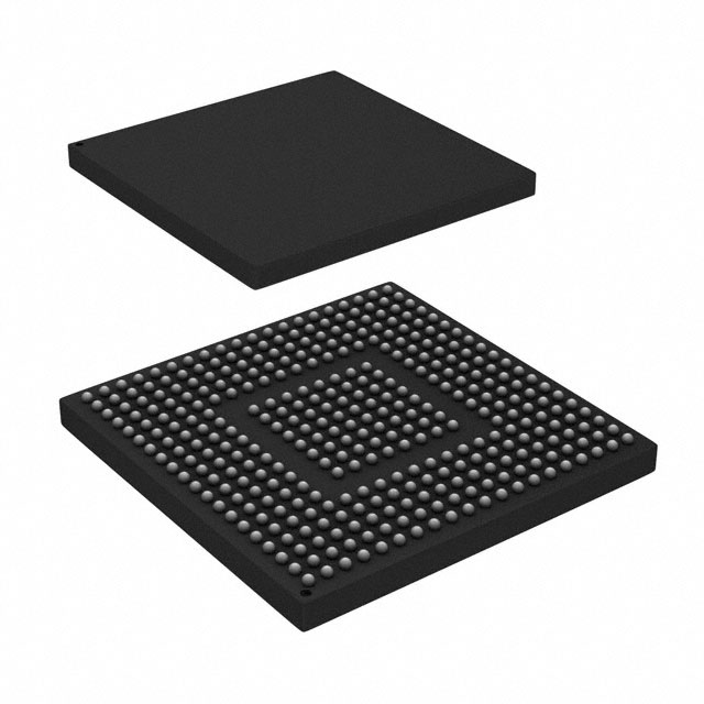
- Part No.:
- PVF62NN151CMK40
- Manufacturer:
- NXP Semiconductors
- Category:
- Microcontrollers
- Package:
- 364-LFBGA
- Datasheet:
-
 PVF62NN151CMK40.pdf
- Description:
- IC MCU 32BIT ROMLESS 364LFBGA
- Quantity:
- Payment:

- Shipping:

Inventory:3,281
Please send an inquiry. Send us your inquiry, and we will respond immediately.
Product details
Overview
PVF62NN151CMK40 from NXP Semiconductors (formerly Freescale) is a dual-core heterogeneous application processor integrating an ARM Cortex-A5 core running at 400 MHz and an ARM Cortex-M4 core configured as primary execution unit, with 1.5 MB on-chip memory (512 KB SRAM + 1 MB graphics SRAM), security-enabled boot via High Assurance Boot (HAB), and 364-ball MAPBGA package. It targets industrial HMI, secure gateway, and real-time control applications requiring concurrent high-level OS and deterministic real-time processing.
For engineers reviewing the PVF62NN151CMK40 datasheet, PVF62NN151CMK40 pinout, PVF62NN151CMK40 application, or PVF62NN151CMK40 equivalent, key selection criteria include M4-primary boot mode, absence of security features (S = N), -40°C to +85°C operating range, 364-BGA mechanical compatibility, and dual-core clock domain isolation for mixed-criticality systems.
Technical Context
The PVF62NN151CMK40 implements a tightly coupled dual-core architecture where the Cortex-M4 operates as the primary boot and real-time controller, while the Cortex-A5 runs Linux or Android in application mode. Memory subsystem includes separate 512 KB ECC-protected SRAM and 1 MB graphics SRAM, with no L2 cache enabled (O = 0N → no L2; O = 1N or 2N required for L2).
Clock architecture uses independent PLLs: PLL1/PLL2 for system (528 MHz), PLL3/PLL7 for USB (480 MHz), PLL5 for Ethernet (125 MHz), PLL4 for audio (variable), and PLL6 for video (variable). The device supports dual 10/100 Ethernet with IEEE 1588 timestamping, dual FlexCAN3 interfaces, and hardware-accelerated cryptographic operations via CAAM only when security is enabled - which this part lacks (S = N).
Key Specifications
| Parameter | Value and Actual Design Meaning |
|---|---|
| A5 Core Speed | 400 MHz - fixed maximum frequency; enables Linux-based UI rendering and network stack without thermal throttling in industrial ambient. |
| M4 Core Role | Primary boot & real-time controller - executes from boot ROM before A5 initialization; handles time-critical I/O, motor control, and safety monitoring. |
| Memory Config | 1.5 MB total: 512 KB ECC SRAM + 1 MB graphics SRAM - supports dual-display DCU operation and secure firmware partitioning. |
| Operating Temp | -40 °C to +85 °C ambient - validated for uncooled industrial enclosures and automotive under-hood edge gateways. |
| Supply Voltage | 3.0 V to 3.6 V - compatible with standard 3.3 V industrial power rails; requires external NPN ballast for 1.2 V core regulation. |
| Package | 364-ball MAPBGA, 17 mm × 17 mm, 0.8 mm pitch - supports high-density routing for dual Ethernet PHYs and DDR3/LPDDR2 interfaces. |
| Security | No Security (S = N) - excludes CAAM, SNVS, HAB, TrustZone, and secure JTAG; simplifies certification but disables encrypted boot and tamper detection. |
Pinout & Package
Package: 364-ball MAPBGA (17 mm × 17 mm, 0.8 mm pitch), RoHS-compliant, moisture sensitivity level 3 (MSL3), lead-free reflow profile peak 260 °C.
| Pin/Terminal | Circuit Role | Design Meaning |
|---|---|---|
| VDD_ARM | A5 Core Power Supply | 1.2 V regulated input; requires external NPN ballast and 4.7 µF decoupling per HPREG spec. |
| VDD_M4 | M4 Core Power Supply | 1.2 V regulated input; shares same regulator domain as A5 but independently monitored. |
| BOOT_MODE[1:0] | Boot Configuration Pins | Hardwired to select primary M4 boot from internal ROM; determines reset vector and initial execution context. |
| ENET0_RXD[3:0] | Ethernet MAC0 Receive Data | LVDS-capable inputs supporting MII/RMII; enables dual 10/100 Ethernet with integrated L2 switch. |
| FLEXCAN0_TX | FlexCAN3 Controller Output | High-speed CAN FD-capable transmitter; supports ISO 11898-1 physical layer with bus fault protection. |
| DCU0_D[23:0] | Display Control Unit 0 Data Bus | 24-bit RGB parallel interface driving SVGA TFT panels up to 800×600 @ 60 Hz. |
Key Features
| Feature | Design Value |
|---|---|
| M4-Primary Boot Mode | Guarantees deterministic startup within 10 ms; isolates real-time control firmware from A5 OS boot sequence and updates. |
| Dual Ethernet with L2 Switch | Enables transparent bridging, VLAN tagging, and IEEE 1588 PTP timestamping on both ports without external switch IC. |
| Quad SPI with XIP | Supports direct code execution from external flash; eliminates boot ROM dependency for field-upgradable firmware images. |
| Hardware CRC Module | Accelerates integrity checks on DMA-transferred data blocks; reduces CPU load by >90% vs software CRC-32. |
| Flexible Clock Architecture | Independent PLL domains allow dynamic frequency scaling of A5, M4, USB, Ethernet, and audio subsystems without cross-domain jitter coupling. |
Applications
| Industrial HMI Gateway | Secure Edge Router |
|---|---|
Use Scenario: Factory-floor operator panel with touchscreen, PLC connectivity, and cloud telemetry upload. IC Role / Device Role / Timing Role: PVF62NN151CMK40 acts as real-time I/O coordinator (M4) and Linux-based UI/network host (A5); dual Ethernet enables isolated control and IT networks. Use Value: Deterministic M4 response <100 µs for emergency stop handling while A5 manages web server and MQTT stack concurrently. | Use Scenario: Field-deployed smart meter aggregation node with dual CAN buses and cellular backhaul. IC Role / Device Role / Timing Role: PVF62NN151CMK40 serves as protocol translator (M4) and secure data concentrator (A5); FlexCAN3 interfaces handle legacy AMI endpoints. Use Value: Dual CAN controllers eliminate need for external CAN bridge ICs; 1.5 MB on-chip memory stores firmware, certificates, and buffered meter reads. |
| Automotive Diagnostic Tool | Medical Device Controller |
Use Scenario: Handheld OBD-II scanner with Wi-Fi, Bluetooth, and UDS diagnostic support. IC Role / Device Role / Timing Role: PVF62NN151CMK40 runs UDS stack on M4 for sub-50 ms diagnostic request/response; A5 hosts Android UI and OTA update manager. Use Value: M4-primary boot ensures immediate CAN bus readiness on power-up; dual USB OTG supports simultaneous debug and peripheral attachment. | Use Scenario: Portable ultrasound console requiring real-time beamforming and DICOM export. IC Role / Device Role / Timing Role: PVF62NN151CMK40 performs FPGA-like signal processing on M4 while A5 renders GUI and manages DICOM over Ethernet. Use Value: Dual 12-bit ADCs (1 MS/s) digitize analog front-end signals; VIU interface captures camera feed for calibration overlays. |
Equivalent & Alternatives
The following parts are listed as comparable options for similar dual-core heterogeneous processor applications.
| Alternative Part | Technical Difference | Application Difference | Selection Advice |
|---|---|---|---|
| MVF60NN151CMK40 | Same dual-core A5+M4, 400 MHz, no security, but M4 not primary boot - boots A5 first, then starts M4. | Less suitable for safety-critical real-time tasks requiring guaranteed M4 startup latency. | Select when A5-centric Linux application dominates and M4 serves auxiliary roles. |
| MVF62NS151CMK40 | Identical M4-primary configuration but with security enabled (S = S): CAAM, SNVS, HAB, TrustZone. | Required for HIPAA/FDA-compliant medical devices or FIPS 140-2 certified infrastructure. | Select when encrypted firmware, secure boot, and tamper detection are mandatory. |
Compared with MVF60NN151CMK40, PVF62NN151CMK40 delivers deterministic M4-first boot critical for functional safety; compared with MVF62NS151CMK40, it trades security features for lower BOM cost and simplified certification in non-regulated industrial use cases.
Availability
PVF62NN151CMK40 is available at Aetrix Electronics and suitable for industrial HMI, edge gateway, and automotive diagnostic applications requiring stable component supply, long-term lifecycle support, and qualified industrial-grade packaging.
Supply support for PVF62NN151CMK40 includes scheduled delivery planning, volume procurement assistance, BOM continuity management, traceable sourcing, and lifecycle availability coordination for OEM customers, industrial embedded developers, connected-device designers, and electronics production programs.
Manufacturer
NXP Semiconductors is a global semiconductor company specializing in secure connectivity solutions for automotive, industrial, and IoT markets, with headquarters in Eindhoven, Netherlands.
The Vybrid VF6xx series - including PVF62NN151CMK40 - was designed to bridge the gap between microcontrollers and application processors, targeting mixed-criticality systems where real-time determinism and rich OS capabilities coexist on a single die.
FAQ
What is the boot sequence of the PVF62NN151CMK40?
The PVF62NN151CMK40 initiates boot exclusively from the Cortex-M4 core, executing firmware from internal ROM or Quad SPI flash. This M4-primary boot ensures sub-10 ms real-time readiness before the Cortex-A5 is initialized or powered up. The A5 core remains held in reset until explicitly released by M4 firmware, enabling strict separation of safety-critical and application-layer functions. PVF62NN151CMK40 does not support A5-first boot modes.
Does the PVF62NN151CMK40 support DDR3 memory interfaces?
Yes, the PVF62NN151CMK40 integrates an 8/16-bit DRAM controller supporting LPDDR2 and DDR3 up to 400 MHz, with ECC support limited to 8-bit configurations only. The controller provides configurable timing parameters, on-die termination, and dynamic power-down modes. PVF62NN151CMK40 requires external DDR3 SDRAM chips and matching layout rules for signal integrity; no internal DRAM is included.
What peripherals are accessible to the Cortex-M4 core on the PVF62NN151CMK40?
The Cortex-M4 core on the PVF62NN151CMK40 has direct access to GPIO, FTM timers, PITs, LPTMR0, UART/SCI, DSPI, I2C, FlexCAN3, ADC/DAC, SAI, and the hardware CRC module. It cannot directly access the Ethernet MACs, USB OTG controllers, or DCU display units - those are routed exclusively to the Cortex-A5 domain. This partitioning enforces hardware-isolated real-time execution on PVF62NN151CMK40.
Is the PVF62NN151CMK40 pin-compatible with other VF6xx variants?
Yes, all VF6xx parts in the 364-ball MAPBGA package - including PVF62NN151CMK40, MVF60NN151CMK40, and MVF62NS151CMK40 - share identical mechanical and electrical pinouts. Signal assignments, power domains, and ball functions are fully consistent across the family. PCB designs can be reused across these variants, though firmware and security configuration must be adjusted per part number.
What is the maximum operating junction temperature for the PVF62NN151CMK40?
The PVF62NN151CMK40 has a maximum junction temperature (TJ) rating of 105 °C, validated under the specified ambient temperature range of -40 °C to +85 °C. Thermal design must ensure that power dissipation - primarily from the A5 core at 400 MHz and M4 core at 167 MHz - does not exceed this limit. The device includes on-die temperature sensors and low-voltage warning circuitry to trigger thermal throttling or safe shutdown if TJ approaches 105 °C.
PVF62NN151CMK40 Specifications
- Product attributes
- Attribute value
- Manufacturer:
- NXP Semiconductors
- Package/Case:
- 364-LFBGA
- Series:
- Vybrid, VF6xx
- Packaging:
- Tray
- Product Status:
- Obsolete
- Programmable:
- Not Verified
- Core Processor:
- ARM® Cortex®-A5/M4
- Core Size:
- 32-Bit Dual-Core
- Speed:
- 400MHz
- Connectivity:
- CANbus, EBI/EMI, Ethernet, I2C, IrDA, LINbus, SCI, SD, SPI, UART/USART, USB OTG
- Peripherals:
- DMA, LVD, WDT
- Number of I/O:
- -
- Program Memory Size:
- -
- Program Memory Type:
- ROMless
- EEPROM Size:
- -
- RAM Size:
- 1.5MB
- Voltage - Supply (Vcc/Vdd):
- 3V ~ 3.6V
- Data Converters:
- A/D 12bit SAR; D/A 12bit
- Oscillator Type:
- Internal
- Operating Temperature:
- -40°C ~ 85°C
- Grade:
- -
- Qualification:
- -
- Mounting Type:
- Surface Mount
- Supplier Device Package:
PVF62NN151CMK40 FAQ
1.How can I place an order for PVF62NN151CMK40 through Aetrix?
Please submit a Request for Quotation (RFQ) for PVF62NN151CMK40 on Aetrix. Our sales agent will provide a competitive quotation and guide you through the order confirmation once you accept the terms.
2.Are the price and stock information for PVF62NN151CMK40 reliable?
The price and inventory of PVF62NN151CMK40 are updated periodically and may fluctuate due to market conditions. Stock and pricing data are typically refreshed every 24 hours. Quotation validity for PVF62NN151CMK40 is usually 5 days.
3.What payment methods are accepted for PVF62NN151CMK40?
We accept Wire Transfer, PayPal, Credit Card, Western Union, MoneyGram, and Escrow for PVF62NN151CMK40 transactions.
Note: Certain payment methods may incur a processing fee.
4.How is shipping managed for PVF62NN151CMK40?
PVF62NN151CMK40 orders can be shipped via leading logistics carriers, including DHL, UPS, FedEx, TNT, or Registered Mail.
Once your PVF62NN151CMK40 order is processed, you will receive an email with the shipment details and tracking number.
Note: Tracking information may take up to 24 hours to appear. Express delivery typically takes 3–5 business days.
5.How can I obtain technical support or documentation for PVF62NN151CMK40?
For technical support, including PVF62NN151CMK40 datasheets, pinout diagrams, or application guidance, please contact our engineering support team. They can provide detailed documentation and assistance for your PVF62NN151CMK40 requirements.
6.How does Aetrix verify that PVF62NN151CMK40 is sourced from the original manufacturer or authorized distributors?
All PVF62NN151CMK40 products on Aetrix are procured from qualified distributors and authorized channels. Our dedicated quality assurance team conducts strict verification, including traceability checks and, if necessary, third-party testing. This ensures that PVF62NN151CMK40 meets industry standards.
7.What is the process for return or replacement of PVF62NN151CMK40?
All PVF62NN151CMK40 units undergo pre-shipment inspection (PSI). If there is an issue with PVF62NN151CMK40, returns or replacements are accepted under the following conditions:
1.Quantity discrepancies, incorrect items, or visible external defects (such as breakage or corrosion), acknowledged by Aetrix.
2.The issue is reported within 90 days of delivery.
3.The PVF62NN151CMK40 part is unused and in its original packaging.
Return procedure for PVF62NN151CMK40:
1.Submit a request within 90 days.
2.Obtain a Return Material Authorization (RMA) from Aetrix.
PVF62NN151CMK40 Tags

-
ATTINY4-TSHR
Microchip Technology
-
ATTINY10-TSHR
Microchip Technology
-
ATTINY10-TS8R
Microchip Technology

-
ATTINY202-SSNR
Microchip Technology
-
ATTINY202-SSFR
Microchip Technology
-
ATTINY402-SSNR
Microchip Technology

-
PIC16F15213T-I/MF
Microchip Technology
-
PIC16F15213-E/MF
Microchip Technology

-
PIC10F200T-I/OT
Microchip Technology
-
ATTINY412-SSNR
Microchip Technology
-
PIC10F202T-I/OT
Microchip Technology

-
ATTINY404-SSNR
Microchip Technology
Tech Hub

A practical engineering guide to 3.3V and 5V logic compatibility, input thresholds, resistor dividers, translator ICs, MOSFET level shifting, I2C pull-ups, timing limits and power-sequencing risks.

The 74HC595 uses push-pull logic outputs, while the TPIC6B595 uses 50 V open-drain DMOS sinks for higher-power loads. This guide compares timing, current limits, 3.3 V interfacing, load wiring, thermal…

The 74HC595 converts serial data into eight stable parallel outputs. This guide covers pin functions, shift and storage timing, OE and MR behavior, drive-current limits, cascading, voltage compatibilit…

A technical comparison of level-sensitive latches and edge-triggered flip-flops, covering timing windows, setup and hold limits, master–slave operation, time borrowing, race-through, HDL inference and…

A D latch stores one bit while Enable controls when data can pass. This reference covers gate-level operation, truth tables, transparency, setup and hold timing, LE versus OE, common ICs and practical …

An SR latch stores one bit through cross-coupled feedback. This engineering reference covers NOR and NAND implementations, truth tables, forbidden-state recovery, gated operation, switch debouncing, fa…

Latch circuits retain one bit through feedback. This technical reference covers SR and D latches, truth tables, transparency, timing limits, latch-versus-flip-flop behavior, applications and common log…

An engineering guide to LED driver operation, constant-current and constant-voltage outputs, linear and switching topologies, dimming, IC selection, calculations, replacement compatibility, and fault c…

Operational amplifier guide covering op amp basics, feedback, ideal vs real op amps, common configurations, buffer circuits, offset, bias current, gain-bandwidth, slew rate, rail-to-rail limits and sel…

Jumper cables guide covering safe connection order, red and black clamp placement, final ground connection, cable gauge, length, clamp quality, copper vs CCA cables, jump starter comparison and battery…


