
 My Inquiry
 My Account


International Rectifier PVI5013RPBF
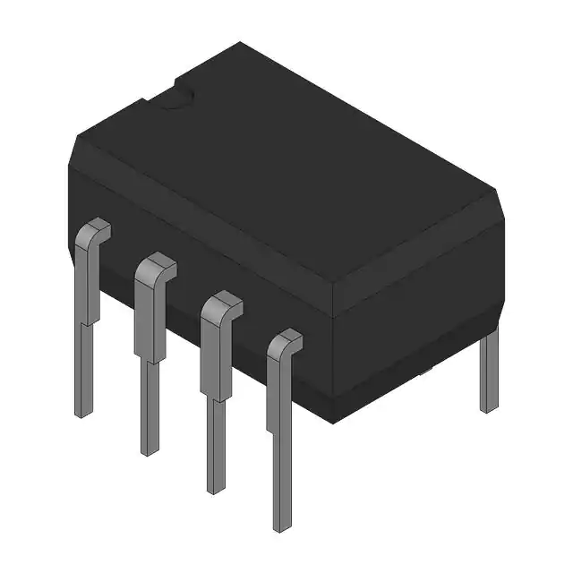
- Part No.:
- PVI5013RPBF
- Manufacturer:
- International Rectifier
- Package:
- 8-DIP (0.300", 7.62mm)
- Datasheet:
-
 PVI5013RPBF.pdf
- Description:
- OPTOELECTRONIC DEVICE
- Quantity:
- Payment:

- Shipping:

Inventory:370
Please send an inquiry. Send us your inquiry, and we will respond immediately.
Product details
Overview
PVI5013RPBF from International Rectifier is a Photovoltaic output optoisolator in the 8-DIP (0.300", 7.62mm) package. It uses an LED input and an optically isolated output structure so that a low-voltage control circuit can drive an isolated photovoltaic or MOSFET-output switching path.
For engineers reviewing the PVI5013RPBF datasheet, PVI5013RPBF pinout, PVI5013RPBF application, or PVI5013RPBF equivalent, this device is commonly used in isolated signal and load switching, photovoltaic gate drive, low-leakage solid-state relay outputs, and service and bom continuity designs. The package and suffix are important because PVI, PVN, PVA, PVT, PVG, and PVR devices often share family concepts but differ in output arrangement, relay rating, and mounting style. The listed output detail is 1 µA output/channel. PVI5013RPBF should therefore be selected by the exact technical documentation output rating rather than by package similarity alone.
Technical Context
In an isolated load-control design, PVI5013RPBF transfers command energy across the optical barrier instead of sharing a direct electrical ground between the controller and the switched side. The input LED current, output leakage, on-resistance or photovoltaic output current, and isolation rating determine the actual usable load condition.
DIP package supporting through-hole assembly, isolation spacing, and serviceable board layouts. The board layout should preserve isolation spacing between input and output pins, avoid leakage paths from flux residue or contamination, and keep the load side routing separate from the logic-side drive network.
For replacement work, the exact output type matters: photovoltaic-output optocouplers are used to drive external MOSFET gates, while PhotoMOS-style relay variants switch load current directly. The PVI5013RPBF technical documentation should be used to confirm which function applies to this orderable line.
Key Specifications
| Parameter | Value and Actual Design Meaning |
|---|---|
| Device Type | Photovoltaic output optoisolator. |
| Package | 8-DIP (0.300", 7.62mm); DIP through-hole package supporting isolation spacing, socketing, and robust board assembly. |
| Current / Output Rating | 1 µA output/channel. |
| Channel Count | 2 channels. |
| Isolation Rating | 3750 Vrms. |
| Output Function | 8 V max photovoltaic output. |
| Switching Timing | 5 ms turn-on, 250 µs turn-off max. |
| Temperature Class | −40°C to +85°C. |
Pinout & Package
The PVI5013RPBF pinout must be reviewed from the exact package drawing because terminal function, thermal path, and mechanical footprint are linked in this product family. 8-DIP (0.300", 7.62mm) package information and Bulk packaging for this line.
For PCB design, use the package drawing and confirm copper area, soldering method, creepage or clearance where applicable, and the final orderable suffix before layout or replacement approval. DIP package supporting through-hole assembly, isolation spacing, and serviceable board layouts.
| Pin / Function | PCB Design and Circuit Role |
|---|---|
| Input LED Anode / Cathode | control-side LED pins provide optical drive energy; input current must follow the technical documentation forward-current and polarity limits. |
| Photovoltaic / MOSFET Output Pins | isolated output pins generate photovoltaic gate drive or provide a MOSFET relay output depending on the exact PVI/PVN/PVA/PVT/PVG family. |
| Isolation Barrier | separates the logic-control side from the load side; PCB creepage and clearance must match the working-voltage requirement. |
| Package Footprint | DIP package supporting through-hole assembly, isolation spacing, and serviceable board layouts. |
Key Features
- Photovoltaic output optoisolator using LED input and optically isolated output behavior.
- Provides galvanic isolation between control electronics and the load-side switching path.
- 8-DIP (0.300", 7.62mm) package determines isolation spacing, board footprint, and soldering method.
- Suitable for low-leakage switching, isolated gate drive, or solid-state relay functions depending on exact family.
- No mechanical contacts, improving lifetime in low-current switching applications.
- Output rating and isolation voltage must be confirmed from the exact technical documentation before substitution.
Applications
| Isolated Signal and Load Switching | Photovoltaic Gate Drive |
|---|---|
|
Use Scenario: Instrumentation, test equipment, telecom interfaces, and isolated low-current load switching. IC Role: PVI5013RPBF transfers control through an optical barrier to an isolated output structure. Use Value: Allows galvanic isolation without mechanical relay contacts. |
Use Scenario: Floating MOSFET gates, analog switch control, and isolated high-side or low-side gate-drive circuits. IC Role: PVI5013RPBF provides photovoltaic output energy or relay switching depending on the exact family. Use Value: Supports isolated drive or switching where a direct ground reference is not available. |
| Low-Leakage Solid-State Relay Outputs | Service and BOM Continuity |
|
Use Scenario: Measurement circuits, multiplexers, security equipment, and compact relay replacement boards. IC Role: PVI5013RPBF provides a solid-state isolated output path. Use Value: Reduces contact wear, bounce, and acoustic noise compared with electromechanical relays. |
Use Scenario: Legacy International Rectifier photovoltaic relay boards requiring the same package footprint. IC Role: PVI5013RPBF maintains the original package and suffix reference for replacement sourcing. Use Value: Helps avoid PCB redesign when output rating and package match the original design. |
Equivalent & Alternatives
When evaluating PVI5013RPBF equivalent devices, engineers should compare only specific orderable alternatives and should verify package footprint, pinout, electrical ratings, thermal data, qualification status, and suffix or packing requirements before substitution.
| Alternative Part | Technical Difference | Application Difference | Selection Advice |
|---|---|---|---|
| PVI5013 | Same base family or close suffix variant; electrical function may be similar, while package, reel orientation, lead finish, or orderable code can differ. | Used when the existing design needs the same functional device with a different supply or assembly code. | Compare PVI5013 against PVI5013RPBF for package drawing, suffix meaning, tape orientation, and documentation revision. |
| PVI5013RSPBF | Same base family or close suffix variant; electrical function may be similar, while package, reel orientation, lead finish, or orderable code can differ. | Used when the existing design needs the same functional device with a different supply or assembly code. | Compare PVI5013RSPBF against PVI5013RPBF for package drawing, suffix meaning, tape orientation, and documentation revision. |
Compared with related alternatives, PVI5013RPBF should remain the preferred sourcing reference when the existing BOM, PCB footprint, and qualification documentation require the exact International Rectifier orderable device.
Quality
PVI5013RPBF should be sourced as original International Rectifier / Infineon inventory through traceable and controlled supply channels. Quality verification may include package inspection, top-mark validation, label and lot review, solderability inspection, moisture-sensitivity handling review, and electrical screening according to the target production requirement.
Because PVI5013RPBF is used in isolated switching and photovoltaic relay circuits, final validation should include the actual PCB footprint, thermal path, electrical stress, operating temperature, and fault-condition behavior. Traceable sourcing helps reduce counterfeit risk and supports repeatable performance in production, repair, and maintenance programs.
Availability
PVI5013RPBF available at Aetrix Electronics and suitable for isolated switching and photovoltaic relay circuits requiring stable component supply, package matching, and controlled replacement planning.
Supply support may include scheduled delivery planning, volume procurement support, BOM continuity assistance, traceable sourcing management, and long-term availability support for OEM manufacturers, repair programs, and electronics production teams.
For production or repair deployment, confirming package type, orderable suffix, lifecycle status, environmental requirement, electrical rating, thermal condition, and sourcing continuity helps reduce procurement risk and improve manufacturing stability.
Manufacturer
International Rectifier was a semiconductor manufacturer known for power MOSFETs, IGBTs, gate drivers, power-management ICs, intelligent power switches, photovoltaic relays, and power modules. International Rectifier products became part of Infineon Technologies' power semiconductor portfolio after the acquisition of International Rectifier.
The PVI5013RPBF ordering line should be reviewed with the relevant International Rectifier legacy technical documentation and Infineon supply-chain references where available. This is especially important for legacy MOSFETs, IRAM modules, PV relay products, and automotive AUIR power devices.
FAQ
What is PVI5013RPBF used for?
PVI5013RPBF is used in isolated switching and photovoltaic relay circuits. The exact application depends on the technical documentation electrical ratings, package, pinout, and thermal capability.
Where can I find the PVI5013RPBF technical documentation?
The PVI5013RPBF technical documentation should be obtained from International Rectifier / Infineon documentation or an authorized technical documentation source. It should be used to confirm ratings, package information, pinout, thermal data, and test conditions.
What should be considered in PVI5013RPBF pinout design?
Pinout design should confirm the package drawing, terminal functions, thermal path, high-current routing or isolation spacing, and whether the orderable suffix changes package or packing details.
Can PVI5013RPBF be used as a direct replacement?
PVI5013RPBF can be used as a direct replacement only when the package footprint, pinout, electrical ratings, thermal behavior, and qualification status match the original design.
What are common PVI5013RPBF equivalent solutions?
Equivalent solutions should be limited to specific orderable devices with verified technical documents. Suffix variants may differ in package, reel orientation, lead finish, qualification, or manufacturing status.
PVI5013RPBF Specifications
- Product attributes
- Attribute value
- Manufacturer:
- International Rectifier
- Series:
- PVI
- Package/Case:
- 8-DIP (0.300", 7.62mm)
- Packaging:
- Bulk
- Product Status:
- Active
- Number of Channels:
- 2
- Voltage - Isolation:
- 3750Vrms
- Current Transfer Ratio (Min):
- -
- Current Transfer Ratio (Max):
- -
- Turn On / Turn Off Time (Typ):
- 5ms, 250µs (Max)
- Rise / Fall Time (Typ):
- -
- Input Type:
- DC
- Output Type:
- Photovoltaic
- Voltage - Output (Max):
- 8V
- Current - Output / Channel:
- 1µA
- Voltage - Forward (Vf) (Typ):
- -
- Current - DC Forward (If) (Max):
- -
- Vce Saturation (Max):
- -
- Grade:
- -
- Qualification:
- -
- Operating Temperature:
- -40°C ~ 85°C
- Mounting Type:
- Through Hole
- Supplier Device Package:
- 8-DIP
PVI5013RPBF FAQ
1.How can I place an order for PVI5013RPBF through Aetrix?
Please submit a Request for Quotation (RFQ) for PVI5013RPBF on Aetrix. Our sales agent will provide a competitive quotation and guide you through the order confirmation once you accept the terms.
2.Are the price and stock information for PVI5013RPBF reliable?
The price and inventory of PVI5013RPBF are updated periodically and may fluctuate due to market conditions. Stock and pricing data are typically refreshed every 24 hours. Quotation validity for PVI5013RPBF is usually 5 days.
3.What payment methods are accepted for PVI5013RPBF?
We accept Wire Transfer, PayPal, Credit Card, Western Union, MoneyGram, and Escrow for PVI5013RPBF transactions.
Note: Certain payment methods may incur a processing fee.
4.How is shipping managed for PVI5013RPBF?
PVI5013RPBF orders can be shipped via leading logistics carriers, including DHL, UPS, FedEx, TNT, or Registered Mail.
Once your PVI5013RPBF order is processed, you will receive an email with the shipment details and tracking number.
Note: Tracking information may take up to 24 hours to appear. Express delivery typically takes 3–5 business days.
5.How can I obtain technical support or documentation for PVI5013RPBF?
For technical support, including PVI5013RPBF datasheets, pinout diagrams, or application guidance, please contact our engineering support team. They can provide detailed documentation and assistance for your PVI5013RPBF requirements.
6.How does Aetrix verify that PVI5013RPBF is sourced from the original manufacturer or authorized distributors?
All PVI5013RPBF products on Aetrix are procured from qualified distributors and authorized channels. Our dedicated quality assurance team conducts strict verification, including traceability checks and, if necessary, third-party testing. This ensures that PVI5013RPBF meets industry standards.
7.What is the process for return or replacement of PVI5013RPBF?
All PVI5013RPBF units undergo pre-shipment inspection (PSI). If there is an issue with PVI5013RPBF, returns or replacements are accepted under the following conditions:
1.Quantity discrepancies, incorrect items, or visible external defects (such as breakage or corrosion), acknowledged by Aetrix.
2.The issue is reported within 90 days of delivery.
3.The PVI5013RPBF part is unused and in its original packaging.
Return procedure for PVI5013RPBF:
1.Submit a request within 90 days.
2.Obtain a Return Material Authorization (RMA) from Aetrix.
PVI5013RPBF Tags
-
LTV-816S
Lite-On Inc.
-
CNY17-3
Vishay Semiconductor Opto Division
-
LTV-816S-TA1
Lite-On Inc.
-
LTV-817
Lite-On Inc.
-
LTV-817S
Lite-On Inc.
-
LTV-817S-TA1
Lite-On Inc.
-
LTV-826S
Lite-On Inc.
-
FOD817CSD
onsemi
.jpg)
-
LTV-356T
Lite-On Inc.
-
LTV-357T
Lite-On Inc.
-
VO618A-3X017T
Vishay Semiconductor Opto Division
-
4N35S-TA1
Lite-On Inc.
Tech Hub

Jumper cables guide covering safe connection order, red and black clamp placement, final ground connection, cable gauge, length, clamp quality, copper vs CCA cables, jump starter comparison and battery…

LDO regulator guide covering low dropout voltage, power dissipation, thermal design, PSRR, output noise, capacitor stability, adjustable LDO circuits, LDO vs buck converter and datasheet selection chec…

Conditional Access Module guide covering CAM meaning, CI/CI+ interface, smart card authorization, DVB security workflow, TV and set-top box compatibility, internal electronics, ESD protection, connecto…

Guide to electronic component obsolescence covering EOL risk, PCN/PDN notices, last-time buy planning, replacement options, form-fit-function validation, counterfeit risk and BOM lifecycle management.

18650 battery guide covering lithium-ion cell basics, 3.6V/3.7V voltage, 4.2V charging, mAh and Wh capacity, protected cells, chargers, BMS, series-parallel packs, holders, welding and sourcing checks.…

Hall effect sensor guide covering working principle, linear and digital sensors, Arduino circuits, current sensing, speed detection, automotive applications, A3144 examples, signal filtering and datash…

Product Change Notification guide for electronic components, covering PCN meaning, PCN vs PDN/EOL, common change types, risk levels, form-fit-function review, engineering validation, BOM control, LTB/L…

A practical guide to blend door actuators, covering HVAC function, symptoms, location, AC and heater issues, reset and calibration, replacement cost, electrical diagnosis, compatibility checks, and rep…

Engineering guide to Raspberry Pi alternatives, covering chip-level differences, Orange Pi, ROCK, Jetson, Banana Pi, NanoPi, Compute Module, Pico, GPIO, camera, HAT compatibility, and replacement risks…

Engineering guide to dynamic load response testing for high-current buck converters, covering load step setup, slew rate, Vcore undershoot, overshoot, recovery time, probe location, output capacitors a…


