
 My Inquiry
 My Account


NXP Semiconductors PX1012AI-EL1/G,557
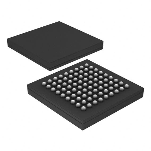
- Part No.:
- PX1012AI-EL1/G,557
- Manufacturer:
- NXP Semiconductors
- Category:
- Specialized
- Package:
- 81-LFBGA
- Datasheet:
-
 PX1012AI-EL1/G,557.pdf
- Description:
- IC INTFACE SPECIALIZED 81LFBGA
- Quantity:
- Payment:

- Shipping:

Inventory:1,200
Please send an inquiry. Send us your inquiry, and we will respond immediately.
Product details
Overview
PX1012AI-EL1/G from NXP Semiconductors (formerly Philips) is a single-lane, 2.5 Gbit/s PCI Express 1.1-compliant stand-alone physical layer (PHY) IC for embedded host and endpoint applications. It implements full SerDes functionality with 8b/10b encoding, clock and data recovery (CDR), elastic buffer, receiver detection, and loopback - all operating within −40 °C to +85 °C industrial temperature range.
For engineers reviewing the PX1012AI-EL1/G datasheet, PX1012AI-EL1/G pinout, PX1012AI-EL1/G application, or PX1012AI-EL1/G equivalent, this device serves as a drop-in PHY solution interfacing FPGA-based MACs via the 250 MHz SSTL_2 PXPIPE interface, supporting L0/L0s/L1 power states, spread-spectrum clocking, and PCIe link training in space-constrained industrial systems.
Technical Context
The PX1012AI-EL1/G integrates a full PCI Express Base Specification Rev. 1.1-compliant PHY layer including CDR, 8b/10b encoder/decoder, elastic buffer, and analog I/O for 2.5 Gbit/s differential signaling. Its PXPIPE interface extends Intel's PIPE v1.0 with source-synchronous TXCLK/RXCLK at 250 MHz and SSTL_2 Class I signaling compatible with FPGA I/O banks.
It supports JTAG IEEE 1149.1 boundary scan with BIST for SerDes and I/O blocks, operates on five independent supply domains (VDD = 1.2 V, VDDA1 = 1.25 V, VDDA2 = 3.3 V, VDDD1 = 3.3 V, VDDD2 = 2.5 V), and delivers <300 mW typical power dissipation in L0 mode while meeting PCIe electrical idle, polarity inversion, and SKP symbol management requirements.
Key Specifications
| Parameter | Value and Actual Design Meaning |
|---|---|
| Data Rate | 2.5 Gbit/s serial line rate - enables full x1 PCIe Gen1 link bandwidth with 250 MB/s usable throughput |
| Interface Standard | PCI Express Base Spec. Rev. 1.1 - ensures interoperability with compliant MACs and endpoints |
| Parallel Interface | 8-bit PXPIPE at 250 MHz with SSTL_2 Class I - matches FPGA I/O voltage and timing without level-shifting |
| Operating Temperature | −40 °C to +85 °C - qualified for industrial control, medical, and ruggedized embedded platforms |
| Power Dissipation | <300 mW in L0 - enables thermal design in dense PCB layouts without forced cooling |
| Reference Clock | 100 MHz ±300 ppm with spread spectrum support - reduces EMI and meets PCIe clock jitter requirements |
| ESD Protection | 2000 V HBM - provides robust handling during board assembly and field operation |
Pinout & Package
LFBGA81 package (9 × 9 × 1.05 mm, SOT643-1), lead-free (SnAgCu solder ball compound), with 81-ball grid array and standard bottom-side thermal pad.
| Pin/Terminal | Circuit Role | Design Meaning |
|---|---|---|
| RX_P / RX_N | Differential receive input pair | 50 Ω on-chip termination; accepts 2.5 Gbit/s PCIe serial stream directly from connector or cable |
| TX_P / TX_N | Differential transmit output pair | 50 Ω on-chip termination; drives 2.5 Gbit/s PCIe signal with built-in de-emphasis |
| TXDATA[7:0] / TXDATAK | Parallel transmit data inputs | 8-bit + K-character input synchronized to TXCLK; connects directly to MAC/FPGA TX data bus |
| RXDATA[7:0] / RXDATAK | Parallel receive data outputs | 8-bit + K-character output synchronized to RXCLK; delivers recovered symbols to MAC/FPGA |
| TXCLK / RXCLK | Source-synchronous clocks | 250 MHz bidirectional clocks - eliminates setup/hold timing closure challenges vs. asynchronous interfaces |
| REFCLK_P / REFCLK_N | Differential reference clock input | 100 MHz PCIe reference clock with 50 Ω on-chip termination; supports spread-spectrum modulation |
| RESET_N | Active-low asynchronous reset | Must be held low until VDD/VDDD/VDDA supplies and REFCLK stabilize (max 64 µs) |
| RXDET_LOOPB | Receiver detect / loopback control | Single-pin dual-function: assert LOW to initiate receiver detection or internal loopback mode |
Key Features
| Feature | Design Value |
|---|---|
| PCIe 1.1 Compliance | Fully implements Base Spec. Rev. 1.1 electrical layer - guarantees link negotiation, training, and error handling with standard root complexes |
| Source-Synchronous PXPIPE | 250 MHz TXCLK/RXCLK eliminates clock domain crossing logic and simplifies FPGA timing closure |
| Integrated Elastic Buffer | 7-symbol depth compensates for ±600 ppm frequency mismatch between link partners - prevents overflow/underflow during SKP management |
| Low-Power State Support | Hardware-managed L0/L0s/L1 transitions with single-cycle PHYSTATUS assertion - enables deterministic power state entry/exit per PCIe spec |
| JTAG + BIST | IEEE 1149.1 interface with on-chip BIST for SerDes and I/O at-speed testing - reduces production test time and validation effort |
Applications
| Industrial FPGA-Based Controllers | Medical Imaging Data Acquisition |
|---|---|
Use Scenario: Real-time sensor data aggregation in programmable logic controllers with PCIe uplink to central processing unit. IC Role / Device Role / Timing Role: Stand-alone PCIe PHY bridging FPGA MAC to backplane or mezzanine card slot. Use Value: Enables deterministic 250 MB/s data transfer with industrial temperature tolerance and low-latency link training. |
Use Scenario: High-fidelity image streaming from digital X-ray or MRI front-end modules to host PC via compact PCIe edge connector. IC Role / Device Role / Timing Role: Physical layer transceiver handling serial link integrity, clock recovery, and 8b/10b decoding for lossless imaging payloads. Use Value: Delivers sub-10 ns symbol alignment and elastic buffer compensation to maintain pixel-perfect timing across variable-length cables. |
| Avionics Data Concentrators | Ruggedized Test Equipment |
Use Scenario: Modular avionics units requiring certified, radiation-tolerant interconnect between mission computers and sensor I/O cards. IC Role / Device Role / Timing Role: PCIe Gen1 PHY providing ESD-hardened, low-jitter serial interface compliant with DO-254 design assurance. Use Value: Supports electrical idle ordered sets and loopback diagnostics essential for in-flight BIT (Built-In Test) procedures. |
Use Scenario: Portable protocol analyzers capturing PCIe traffic in field-deployed telecom or defense infrastructure. IC Role / Device Role / Timing Role: Stand-alone PHY enabling direct FPGA capture of raw 2.5 Gbit/s lane activity with real-time error injection and status reporting. Use Value: Provides RXSTATUS-encoded error visibility (8b/10b decode, disparity, buffer overflow) for precise fault isolation without MAC dependency. |
Equivalent & Alternatives
The following parts are listed as comparable options for similar PCIe Gen1 PHY applications.
| Alternative Part | Technical Difference | Application Difference | Selection Advice |
|---|---|---|---|
| IDT8N34S2101BGI | Quad-channel PCIe Gen1 PHY; requires external reference clock buffer; no integrated elastic buffer | Targeted at multi-lane switch fabric designs rather than single-lane endpoint use | Select only when scaling beyond x1 or requiring multi-lane synchronization |
| TI TSB51101ZQLR | Single-lane PCIe Gen1 PHY with identical PXPIPE interface but commercial temp range (0 °C to +70 °C) and higher 350 mW L0 power | Suitable for lab-grade or non-ruggedized equipment where industrial temp rating is not required | Choose if cost sensitivity outweighs extended temperature need and thermal budget allows |
Compared with IDT8N34S2101BGI and TI TSB51101ZQLR, the PX1012AI-EL1/G uniquely combines industrial temperature operation, sub-300 mW L0 power, and full elastic buffer implementation in a single-lane LFBGA81 package - making it optimal for space- and reliability-constrained embedded PCIe endpoints.
Availability
PX1012AI-EL1/G is available at Aetrix Electronics and suitable for industrial FPGA-based controllers, medical imaging data acquisition, and avionics data concentrators requiring stable component supply across extended lifecycle programs.
Supply support for PX1012AI-EL1/G includes scheduled delivery planning, volume procurement assistance, BOM continuity management, traceable sourcing, and lifecycle availability coordination for OEM customers, industrial embedded developers, connected-device designers, and electronics production programs.
Manufacturer
NXP Semiconductors is a global semiconductor leader focused on secure connectivity solutions for automotive, industrial, and IoT applications, with deep heritage in high-speed interface IP from its Philips Semiconductor roots.
The PX1012AI-EL1/G belongs to NXP's legacy PCI Express PHY product line, designed specifically to enable FPGA- and ASIC-based PCIe endpoint integration in thermally demanding, long-lifecycle industrial systems.
FAQ
What is the operating temperature range for the PX1012AI-EL1/G?
The PX1012AI-EL1/G is rated for industrial temperature operation from −40 °C to +85 °C. This specification is confirmed in the official Philips/NXP product data sheet (Rev. 02, May 2006), Table 1 and Ordering Information section, and distinguishes it from commercial variants like PX1012A-EL1/G (0 °C to +70 °C). The "I" suffix explicitly denotes industrial grade.
Does the PX1012AI-EL1/G support PCIe Gen2 or higher speeds?
No, the PX1012AI-EL1/G supports only PCIe Gen1 at 2.5 Gbit/s. It complies exclusively with PCI Express Base Specification Rev. 1.0a and Rev. 1.1, as stated in the General Description and Features sections of the datasheet. It does not implement 5.0 Gbit/s signaling, 128b/130b encoding, or Gen2+ equalization features.
What power supplies are required for the PX1012AI-EL1/G?
The PX1012AI-EL1/G requires five independent supply rails: VDD = 1.2 V (high-speed serial I/O), VDDA1 = 1.25 V (analog SerDes core), VDDA2 = 3.3 V (analog SerDes I/O), VDDD1 = 3.3 V (JTAG I/O), and VDDD2 = 2.5 V (SSTL_2 I/O). These are specified in Table 12 (Pin Descriptions) and Table 1 (Quick Reference Data) of the datasheet.
Is the PX1012AI-EL1/G pin-compatible with the PX1011A series?
Yes, the PX1012AI-EL1/G shares identical LFBGA81 pinout and ball mapping with PX1011A-EL1/G, PX1011AI-EL1/G, and PX1012A-EL1/G, as confirmed in Figures 2–3 and Tables 5–12 of the datasheet. All variants use the same SOT643-1 package footprint and signal assignment, enabling direct PCB reuse across the PX1011A/PX1012A family.
How does the PX1012AI-EL1/G handle clock tolerance between link partners?
The PX1012AI-EL1/G uses an elastic buffer capable of holding ≥7 symbols to absorb ±600 ppm frequency differences. It dynamically inserts or removes SKP ordered sets in the received data stream and signals these actions to the MAC via RXSTATUS[2:0] - ensuring continuous data flow without buffer overflow or underflow, as detailed in Section 8.9 and Figure 9–10 of the datasheet.
PX1012AI-EL1/G,557 Specifications
- Product attributes
- Attribute value
- Manufacturer:
- NXP Semiconductors
- Series:
- -
- Package/Case:
- 81-LFBGA
- Packaging:
- Tray
- Product Status:
- Obsolete
- Applications:
- PCI Express MAX to PCI Express PHY
- Interface:
- IEEE 1149.1
- Voltage - Supply:
- 1.2V
- Supplier Device Package:
- 81-LFBGA (9x9)
- Grade:
- -
- Qualification:
- -
- Mounting Type:
- Surface Mount
PX1012AI-EL1/G,557 FAQ
1.How can I place an order for PX1012AI-EL1/G,557 through Aetrix?
Please submit a Request for Quotation (RFQ) for PX1012AI-EL1/G,557 on Aetrix. Our sales agent will provide a competitive quotation and guide you through the order confirmation once you accept the terms.
2.Are the price and stock information for PX1012AI-EL1/G,557 reliable?
The price and inventory of PX1012AI-EL1/G,557 are updated periodically and may fluctuate due to market conditions. Stock and pricing data are typically refreshed every 24 hours. Quotation validity for PX1012AI-EL1/G,557 is usually 5 days.
3.What payment methods are accepted for PX1012AI-EL1/G,557?
We accept Wire Transfer, PayPal, Credit Card, Western Union, MoneyGram, and Escrow for PX1012AI-EL1/G,557 transactions.
Note: Certain payment methods may incur a processing fee.
4.How is shipping managed for PX1012AI-EL1/G,557?
PX1012AI-EL1/G,557 orders can be shipped via leading logistics carriers, including DHL, UPS, FedEx, TNT, or Registered Mail.
Once your PX1012AI-EL1/G,557 order is processed, you will receive an email with the shipment details and tracking number.
Note: Tracking information may take up to 24 hours to appear. Express delivery typically takes 3–5 business days.
5.How can I obtain technical support or documentation for PX1012AI-EL1/G,557?
For technical support, including PX1012AI-EL1/G,557 datasheets, pinout diagrams, or application guidance, please contact our engineering support team. They can provide detailed documentation and assistance for your PX1012AI-EL1/G,557 requirements.
6.How does Aetrix verify that PX1012AI-EL1/G,557 is sourced from the original manufacturer or authorized distributors?
All PX1012AI-EL1/G,557 products on Aetrix are procured from qualified distributors and authorized channels. Our dedicated quality assurance team conducts strict verification, including traceability checks and, if necessary, third-party testing. This ensures that PX1012AI-EL1/G,557 meets industry standards.
7.What is the process for return or replacement of PX1012AI-EL1/G,557?
All PX1012AI-EL1/G,557 units undergo pre-shipment inspection (PSI). If there is an issue with PX1012AI-EL1/G,557, returns or replacements are accepted under the following conditions:
1.Quantity discrepancies, incorrect items, or visible external defects (such as breakage or corrosion), acknowledged by Aetrix.
2.The issue is reported within 90 days of delivery.
3.The PX1012AI-EL1/G,557 part is unused and in its original packaging.
Return procedure for PX1012AI-EL1/G,557:
1.Submit a request within 90 days.
2.Obtain a Return Material Authorization (RMA) from Aetrix.
PX1012AI-EL1/G,557 Tags

-
NVT4857UKAZ
NXP Semiconductors

-
TCA8418RTWR
Texas Instruments

-
PCA9546APWR
Texas Instruments

-
MD0100N8-G
Microchip Technology

-
PCA9548APW,118
NXP Semiconductors

-
PCA9540BDP,118
NXP Semiconductors

-
PCA9548APWR
Texas Instruments

-
PCA9546APW,118
NXP Semiconductors

-
PTN3360DBS,518
NXP Semiconductors

-
PCA9546ABS,118
NXP Semiconductors

-
PCA9518PWR
Texas Instruments

-
PCA9545APW,118
NXP Semiconductors
Tech Hub

A practical engineering guide to 3.3V and 5V logic compatibility, input thresholds, resistor dividers, translator ICs, MOSFET level shifting, I2C pull-ups, timing limits and power-sequencing risks.

The 74HC595 uses push-pull logic outputs, while the TPIC6B595 uses 50 V open-drain DMOS sinks for higher-power loads. This guide compares timing, current limits, 3.3 V interfacing, load wiring, thermal…

The 74HC595 converts serial data into eight stable parallel outputs. This guide covers pin functions, shift and storage timing, OE and MR behavior, drive-current limits, cascading, voltage compatibilit…

A technical comparison of level-sensitive latches and edge-triggered flip-flops, covering timing windows, setup and hold limits, master–slave operation, time borrowing, race-through, HDL inference and…

A D latch stores one bit while Enable controls when data can pass. This reference covers gate-level operation, truth tables, transparency, setup and hold timing, LE versus OE, common ICs and practical …

An SR latch stores one bit through cross-coupled feedback. This engineering reference covers NOR and NAND implementations, truth tables, forbidden-state recovery, gated operation, switch debouncing, fa…

Latch circuits retain one bit through feedback. This technical reference covers SR and D latches, truth tables, transparency, timing limits, latch-versus-flip-flop behavior, applications and common log…

An engineering guide to LED driver operation, constant-current and constant-voltage outputs, linear and switching topologies, dimming, IC selection, calculations, replacement compatibility, and fault c…

Operational amplifier guide covering op amp basics, feedback, ideal vs real op amps, common configurations, buffer circuits, offset, bias current, gain-bandwidth, slew rate, rail-to-rail limits and sel…

Jumper cables guide covering safe connection order, red and black clamp placement, final ground connection, cable gauge, length, clamp quality, copper vs CCA cables, jump starter comparison and battery…


