
 My Inquiry
 My Account


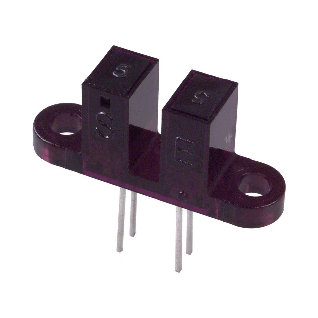
onsemi QVB11134
- Part No.:
- QVB11134
- Manufacturer:
- onsemi
- Package:
- Module, PC Pins, Slot Type
- Datasheet:
-
 QVB11134.pdf
- Description:
- SENSOR OPT SLOT PHOTOTRANS MODUL
- Quantity:
- Payment:

- Shipping:

Inventory:1,085
Please send an inquiry. Send us your inquiry, and we will respond immediately.
Product details
Overview
QVB11134 from Fairchild Semiconductor is a slotted optical switch with phototransistor output, designed for object detection and position sensing in industrial automation and consumer electronics. It features 5 mm slot width, 70 V collector-emitter breakdown voltage, 50 mA collector current rating, and operates across -40°C to +85°C ambient temperature range.
For engineers reviewing the QVB11134 datasheet, pinout, applications, or equivalent options, key selection criteria include slot geometry compatibility, phototransistor saturation behavior, dark current specification, and response time under defined LED drive conditions.
Technical Context
The QVB11134 integrates an infrared LED emitter and NPN silicon phototransistor in a single molded package with a 5 mm wide U-shaped slot. Detection occurs when an opaque object interrupts the optical path between emitter and detector, causing phototransistor current to drop below threshold.
It operates with DC or pulsed LED drive; typical forward voltage is 1.3 V at 20 mA, and phototransistor output exhibits 100 µs turn-on/turn-off times at specified load and drive conditions. No internal signal conditioning or hysteresis is provided.
Key Specifications
| Parameter | Value and Actual Design Meaning |
|---|---|
| Slot Width | 5 mm - defines maximum object thickness detectable without mechanical interference |
| Collector-Emitter Breakdown Voltage | 70 V - sets maximum allowable supply voltage on phototransistor collector |
| Continuous Collector Current | 50 mA - limits maximum load current the phototransistor can sink reliably |
| Operating Temperature Range | -40°C to +85°C - specifies ambient thermal envelope for guaranteed performance |
| Response Time (Turn-on / Turn-off) | 100 µs / 100 µs - determines minimum detectable object transit speed at given slot geometry |
| LED Forward Voltage | 1.3 V @ 20 mA - defines required drive voltage headroom for constant-current LED bias |
Pinout & Package
QVB11134 uses a 4-pin DIP package with gull-wing leads. Pin 1 is LED anode, Pin 2 is LED cathode, Pin 3 is phototransistor emitter, Pin 4 is phototransistor collector.
| Pin/Terminal | Circuit Role | Design Meaning |
|---|---|---|
| Pin 1 | LED Anode | Positive terminal of integrated infrared emitter; requires current-limiting resistor when driven from voltage source |
| Pin 2 | LED Cathode | Ground reference for LED; connects to circuit common or driver low-side switch |
| Pin 3 | Phototransistor Emitter | Emitter output node; typically tied to ground for common-emitter switching configuration |
| Pin 4 | Phototransistor Collector | Switched output node; pulls low when object blocks light, high-impedance when unblocked |
Key Features
| Feature | Design Value |
|---|---|
| Integrated emitter-detector pair | Eliminates alignment sensitivity and enables compact, repeatable mechanical mounting |
| 5 mm slot width | Accommodates standard industrial actuator tabs and encoder flags without custom tooling |
| DC-coupled phototransistor output | Supports direct interface to TTL/CMOS logic inputs without external level-shifting circuitry |
| Wide operating temperature range | Enables deployment in uncontrolled environments such as factory floors and outdoor enclosures |
Applications
| Industrial Position Sensing | Printer Paper Jam Detection |
|---|---|
Use Scenario: Detecting presence/absence of metal or plastic components on conveyor lines or robotic end-effectors. IC Role / Device Role / Timing Role: Slotted optical switch providing digital on/off feedback for PLC input modules. Use Value: 5 mm slot accommodates standard machine parts; 70 V breakdown allows direct connection to 24 V industrial control rails. | Use Scenario: Monitoring paper path in laser and inkjet printers to prevent feed errors and jams. IC Role / Device Role / Timing Role: Object-interrupt sensor triggering microcontroller interrupt on paper edge transition. Use Value: 100 µs response time supports high-speed paper transport up to 300 mm/s without missed events. |
| Rotary Encoder Index Detection | Automated Door Obstacle Sensing |
Use Scenario: Identifying home position in motorized valve actuators or CNC axis homing sequences. IC Role / Device Role / Timing Role: Index pulse generator synchronized to mechanical rotation via flag interruption. Use Value: Stable dark current (<100 nA) ensures clean logic transitions even after extended standby periods. | Use Scenario: Safety interlock in sliding or swing doors to halt motion when obstruction is detected. IC Role / Device Role / Timing Role: Real-time presence detector feeding safety-rated controller input. Use Value: -40°C to +85°C operation supports outdoor installation; no internal hysteresis avoids false triggers during slow object approach. |
Equivalent & Alternatives
The following parts are listed as comparable options for similar slotted optical switch applications.
| Alternative Part | Technical Difference | Application Difference | Selection Advice |
|---|---|---|---|
| Everlight ITD1205 | Same 5 mm slot width; 60 V VCEO; 20 mA IC rating; faster 50 µs response | Lower current capability limits use with heavy pull-up loads; preferred where speed > robustness | Select ITD1205 when system timing budget is tight and load current ≤20 mA |
| Vishay TCST1103 | 3.5 mm slot width; 30 V VCEO; 20 mA IC; integrated lens improves sensitivity | Narrower slot restricts object size; lower voltage rating requires 5 V or 12 V supply only | Select TCST1103 for space-constrained PCB layouts where smaller objects must be detected |
Compared with QVB11134, ITD1205 offers higher speed but reduced current drive, while TCST1103 trades slot width and voltage margin for compactness and optical gain-choice depends on mechanical envelope, supply rail, and load requirements.
Availability
QVB11134 is available at Aetrix Electronics and suitable for industrial automation, printer subsystems, and motion control applications requiring stable component supply and long-term manufacturability.
Supply support for QVB11134 includes scheduled delivery planning, volume procurement assistance, BOM continuity management, traceable sourcing, and lifecycle availability coordination for OEM customers, industrial embedded developers, connected-device designers, and electronics production programs.
Manufacturer
Fairchild Semiconductor was a U.S.-based semiconductor company specializing in power management, analog, and optoelectronic components before its acquisition by ON Semiconductor in 2016.
The QVB11134 belongs to Fairchild's legacy slotted optoswitch product line, engineered for reliable object detection in cost-sensitive industrial and office equipment.
FAQ
What is the maximum recommended LED forward current for QVB11134?
The QVB11134 datasheet specifies 50 mA as the absolute maximum DC forward current for the integrated infrared LED. For continuous operation, Fairchild recommends limiting LED current to 20 mA to ensure long-term reliability and stable optical output. Exceeding 20 mA without pulse modulation may accelerate LED degradation. The QVB11134 must be used with appropriate series resistance to enforce this limit under the applied drive voltage.
Does QVB11134 include built-in hysteresis or Schmitt-trigger functionality?
No, the QVB11134 does not include internal hysteresis or signal conditioning circuitry. Its phototransistor output responds linearly to incident light intensity, meaning output state transitions occur gradually near the detection threshold. System-level hysteresis must be implemented externally using comparator circuits or microcontroller firmware. This design preserves flexibility but requires careful attention to noise margins in the QVB11134 application.
Can QVB11134 operate directly from a 24 V supply?
Yes, the phototransistor section of QVB11134 supports up to 70 V collector-emitter voltage, making it compatible with direct connection to 24 V industrial control rails when used in open-collector configuration with appropriate pull-up. However, the LED section requires separate current-limited biasing-typically 1.3 V forward drop at 20 mA-so a 24 V supply must never be applied directly across pins 1 and 2. The QVB11134 LED must always be driven through a series resistor or constant-current source.
What is the typical dark current of QVB11134 at 25°C?
The QVB11134 exhibits a typical dark current of 100 nA at 25°C and VCE = 5 V, with a maximum specified value of 500 nA over the full -40°C to +85°C temperature range. This low leakage ensures clean logic-high states when the slot is unobstructed, especially important in battery-powered or low-power sleep-mode applications. Dark current increases with temperature, so system design must account for worst-case values at maximum operating temperature for the QVB11134.
Is QVB11134 RoHS compliant and halogen-free?
Yes, QVB11134 is RoHS compliant and halogen-free per Fairchild's product change notification PCN-12-001. The device meets EU Directive 2011/65/EU and contains no lead, mercury, cadmium, hexavalent chromium, polybrominated biphenyls (PBB), or polybrominated diphenyl ethers (PBDE). Material declarations and test reports for the QVB11134 are available through authorized distributors upon request.
QVB11134 Specifications
- Product attributes
- Attribute value
- Manufacturer:
- onsemi
- Series:
- QVB
- Package/Case:
- Module, PC Pins, Slot Type
- Packaging:
- Tube
- Product Status:
- Obsolete
- Sensing Distance:
- 0.125" (3.18mm)
- Sensing Method:
- Through-Beam
- Output Configuration:
- Phototransistor
- Current - DC Forward (If) (Max):
- 50 mA
- Current - Collector (Ic) (Max):
- 40 mA
- Voltage - Collector Emitter Breakdown (Max):
- 30 V
- Response Time:
- -
- Operating Temperature:
- -40°C ~ 85°C
- Grade:
- -
- Qualification:
- -
- Mounting Type:
- Through Hole, Flange
QVB11134 FAQ
1.How can I place an order for QVB11134 through Aetrix?
Please submit a Request for Quotation (RFQ) for QVB11134 on Aetrix. Our sales agent will provide a competitive quotation and guide you through the order confirmation once you accept the terms.
2.Are the price and stock information for QVB11134 reliable?
The price and inventory of QVB11134 are updated periodically and may fluctuate due to market conditions. Stock and pricing data are typically refreshed every 24 hours. Quotation validity for QVB11134 is usually 5 days.
3.What payment methods are accepted for QVB11134?
We accept Wire Transfer, PayPal, Credit Card, Western Union, MoneyGram, and Escrow for QVB11134 transactions.
Note: Certain payment methods may incur a processing fee.
4.How is shipping managed for QVB11134?
QVB11134 orders can be shipped via leading logistics carriers, including DHL, UPS, FedEx, TNT, or Registered Mail.
Once your QVB11134 order is processed, you will receive an email with the shipment details and tracking number.
Note: Tracking information may take up to 24 hours to appear. Express delivery typically takes 3–5 business days.
5.How can I obtain technical support or documentation for QVB11134?
For technical support, including QVB11134 datasheets, pinout diagrams, or application guidance, please contact our engineering support team. They can provide detailed documentation and assistance for your QVB11134 requirements.
6.How does Aetrix verify that QVB11134 is sourced from the original manufacturer or authorized distributors?
All QVB11134 products on Aetrix are procured from qualified distributors and authorized channels. Our dedicated quality assurance team conducts strict verification, including traceability checks and, if necessary, third-party testing. This ensures that QVB11134 meets industry standards.
7.What is the process for return or replacement of QVB11134?
All QVB11134 units undergo pre-shipment inspection (PSI). If there is an issue with QVB11134, returns or replacements are accepted under the following conditions:
1.Quantity discrepancies, incorrect items, or visible external defects (such as breakage or corrosion), acknowledged by Aetrix.
2.The issue is reported within 90 days of delivery.
3.The QVB11134 part is unused and in its original packaging.
Return procedure for QVB11134:
1.Submit a request within 90 days.
2.Obtain a Return Material Authorization (RMA) from Aetrix.
QVB11134 Tags
-
GP1S094HCZ0F
SHARP/Socle Technology
-
GP1S092HCPIF
SHARP/Socle Technology
-
GP1S396HCPSF
SHARP/Socle Technology
-
LTH-301-07
Lite-On Inc.
-
RPI-352
Rohm Semiconductor
-
RPI-0226
Rohm Semiconductor
-
TCPT1300X01
Vishay Semiconductor Opto Division
-
EE-SX1320
Omron Electronics Inc-EMC Div

-
TCUT1300X01
Vishay Semiconductor Opto Division
-
EE-SX1103
Omron Electronics Inc-EMC Div

-
H22A1
Isocom Components 2004 LTD
-
EE-SX1041
Omron Electronics Inc-EMC Div
Tech Hub

Counterfeit components can hide behind convincing markings and passing basic function tests. This engineering reference covers source traceability, external inspection, X-ray, XRF, electrical testing, …

A practical engineering and sourcing framework covering lifecycle verification, lifetime-buy calculations, replacement qualification, supplier checks and counterfeit-risk controls.

TTL and CMOS logic families differ in thresholds, loading, output drive, power and timing. This engineering guide compares 74HC and 74HCT, calculates noise margins and checks 3.3 V/5 V compatibility.

A practical engineering guide to 3.3V and 5V logic compatibility, input thresholds, resistor dividers, translator ICs, MOSFET level shifting, I2C pull-ups, timing limits and power-sequencing risks.

The 74HC595 uses push-pull logic outputs, while the TPIC6B595 uses 50 V open-drain DMOS sinks for higher-power loads. This guide compares timing, current limits, 3.3 V interfacing, load wiring, thermal…

The 74HC595 converts serial data into eight stable parallel outputs. This guide covers pin functions, shift and storage timing, OE and MR behavior, drive-current limits, cascading, voltage compatibilit…

A technical comparison of level-sensitive latches and edge-triggered flip-flops, covering timing windows, setup and hold limits, master–slave operation, time borrowing, race-through, HDL inference and…

A D latch stores one bit while Enable controls when data can pass. This reference covers gate-level operation, truth tables, transparency, setup and hold timing, LE versus OE, common ICs and practical …

An SR latch stores one bit through cross-coupled feedback. This engineering reference covers NOR and NAND implementations, truth tables, forbidden-state recovery, gated operation, switch debouncing, fa…

Latch circuits retain one bit through feedback. This technical reference covers SR and D latches, truth tables, transparency, timing limits, latch-versus-flip-flop behavior, applications and common log…


