
 My Inquiry
 My Account


Renesas R5F104GDGFB#30
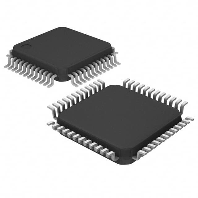
- Part No.:
- R5F104GDGFB#30
- Manufacturer:
- Renesas
- Category:
- Microcontrollers
- Package:
- 48-LQFP
- Datasheet:
-
 R5F104GDGFB#30.pdf
- Description:
- IC MCU 16BIT 64KB FLASH 48LFQFP
- Quantity:
- Payment:

- Shipping:

Inventory:1,123
Please send an inquiry. Send us your inquiry, and we will respond immediately.
Product details
Overview
R5F104GDGFB#30 from Renesas is a 48-pin LFQFP-packaged RL78/G14 16-bit microcontroller with 128 KB flash, 12 KB RAM, and industrial-grade operation up to +105°C. It delivers 44 DMIPS at 32 MHz, consumes 66 μA/MHz active and 0.60 μA in RTC+LVD-only mode, and integrates UART, I²C, SPI, 16-bit timers, 10-bit ADC (16 channels), and on-chip RTC with calendar support - deployed in motor control and sensor interface modules.
For engineers reviewing the R5F104GDGFB#30 datasheet, R5F104GDGFB#30 pinout, R5F104GDGFB#30 application, or R5F104GDGFB#30 equivalent, key selection criteria include its 48-pin LFQFP-0.5 mm pitch package, -40°C to +105°C industrial temperature grade (G-suffix), 128 KB code flash / 8 KB data flash memory split, and integrated event link controller (ELC) for deterministic peripheral triggering.
Technical Context
The R5F104GDGFB#30 implements the RL78 CPU core with 3-stage pipeline CISC architecture, supporting instruction execution times from 0.03125 µs (32 MHz high-speed mode) to 30.5 µs (32.768 kHz ultra-low-power mode). It features a dedicated low-speed on-chip oscillator for watchdog timer operation and supports background operation (BGO) during data flash rewriting.
Its peripheral set includes 8-channel 16-bit Timer Array Unit (TAU), 1-channel 12-bit interval timer, 1-channel real-time clock with alarm/calendar, and 19–26 configurable event signals routed via Event Link Controller (ELC) to peripherals without CPU intervention - enabling deterministic timing-critical tasks in battery-powered industrial nodes.
Key Specifications
| Parameter | Value and Actual Design Meaning |
|---|---|
| Core Architecture | RL78 16-bit CISC with 3-stage pipeline; enables deterministic interrupt latency and compact code density for resource-constrained embedded control. |
| Max Operating Frequency | 32 MHz; delivers 44 DMIPS performance while maintaining ultra-low power consumption (66 μA/MHz). |
| Flash Memory | 128 KB code flash + 8 KB data flash; supports self-programming with boot swapping and flash shield window for secure firmware updates. |
| RAM Size | 12 KB on-chip RAM; sufficient for real-time control stacks, communication buffers, and sensor fusion variables in standalone edge nodes. |
| ADC Resolution & Channels | 10-bit resolution, 16 analog input channels; supports simultaneous sampling of motor phase currents and temperature/voltage monitoring. |
| Operating Temperature | -40°C to +105°C (G-grade); qualified for under-hood automotive subsystems and industrial PLC I/O modules. |
| Supply Voltage Range | 1.6 V to 5.5 V; allows direct interfacing with 3.3 V and 5 V peripherals without level-shifting in mixed-voltage systems. |
Pinout & Package
Package: 48-pin LFQFP (7 × 7 mm, 0.5 mm pitch), lead-free, RoHS-compliant. Pin 1 marked by index notch; exposed pad not present (unlike HWQFN variants).
| Pin/Terminal | Circuit Role | Design Meaning |
|---|---|---|
| P121/X1 | Crystal input | Connects to 32.768 kHz tuning-fork crystal for RTC accuracy; requires external load capacitors per layout guidelines. |
| P122/X2/EXCLK | Crystal output / external clock input | Drives crystal resonator or accepts external clock source; enables precise timekeeping or synchronous system clocking. |
| RESET | Active-low reset input | Asynchronous reset assertion halts CPU and peripherals; debounced externally or via internal POR/LVD circuitry. |
| REGC | Regulator bypass capacitor terminal | Must be connected to VSS via 0.47–1 µF capacitor to stabilize internal voltage regulator for analog/RTC stability. |
| P16/TI01/TO01/INTP5/TRDIOC0/IVREF0 | Multi-function I/O | Configurable as timer input/output, interrupt, serial interface signal, or internal reference voltage output - reduces external component count. |
| P60/SCLA0 | I²C clock line | Dedicated hardware I²C bus clock pin; supports standard/fast-mode speeds up to 400 kHz for sensor hub communication. |
Key Features
| Feature | Design Value |
|---|---|
| SNOOZE mode operation | Enables UART/I²C wake-up from ultra-low-power state without full CPU restart - cuts average system current in periodic polling applications. |
| Event Link Controller (ELC) | Routes 19–26 peripheral events directly to target functions (e.g., ADC trigger → DMA transfer), eliminating CPU overhead and jitter in time-critical sequences. |
| Data flash BGO | Permits concurrent program execution from flash while rewriting 4–8 KB data flash - essential for logging runtime parameters without service interruption. |
| On-chip LVD with 14 levels | Configurable voltage detector provides programmable brown-out reset or interrupt at thresholds from 1.6 V to 4.2 V - supports graceful shutdown in wide-input power supplies. |
| Peripheral I/O redirection | Allows remapping of key functions (e.g., UART, timer) to alternate pins via PIOR registers - improves PCB layout flexibility and avoids signal congestion. |
Applications
| Motor Control Interface | Sensor Data Acquisition |
|---|---|
Use Scenario: Brushless DC motor drive in HVAC blower module requiring commutation timing, current sensing, and thermal protection. IC Role / Device Role / Timing Role: Main system controller executing FOC algorithm, sampling 3-phase currents via 10-bit ADC, and generating PWM via TAU timers with ELC-synchronized dead-time insertion. Use Value: Integrated 16-bit timers with complementary outputs and hardware-triggered ADC reduce MCU-to-gate-driver latency to <1 µs, improving torque ripple suppression. | Use Scenario: Industrial environmental monitor collecting temperature, humidity, and CO₂ via I²C sensors and analog transducers. IC Role / Device Role / Timing Role: Sensor hub managing multi-protocol interfaces (I²C, UART, analog ADC), timestamping readings with RTC calendar, and buffering data in 12 KB RAM before wireless upload. Use Value: 16-channel 10-bit ADC with internal 1.45 V reference enables ratiometric measurement of 4–20 mA loops without external precision references. |
| Smart Power Outlet | Industrial PLC I/O Module |
Use Scenario: Energy-monitoring outlet with relay control, current/voltage measurement, and local BLE gateway. IC Role / Device Role / Timing Role: System-on-chip handling AC zero-cross detection (via comparator), RMS calculation, relay timing, and BLE UART bridge using SNOOZE mode between measurements. Use Value: 0.60 μA STOP mode with RTC+LVD active extends battery backup life to >1 year during mains failure, preserving metering state. | Use Scenario: DIN-rail mounted digital input module accepting 24 V DC field signals with surge protection and status reporting. IC Role / Device Role / Timing Role: Isolated input conditioner with programmable debounce (via 16-bit timers), LED status driver, and Modbus RTU over UART with hardware FIFO management. Use Value: -40°C to +105°C rating ensures reliable operation inside hot control cabinets; 1.6–5.5 V supply range accommodates aging 24 V rails down to 21 V. |
Equivalent & Alternatives
The following parts are listed as comparable options for similar 16-bit microcontroller applications.
| Alternative Part | Technical Difference | Application Difference | Selection Advice |
|---|---|---|---|
| R5F104GEAFB#30 | Same 48-pin LFQFP package, but 64 KB flash / 5.5 KB RAM; lacks VCOUT0/VCOUT1 comparator outputs. | Suitable for simpler control tasks without analog feedback conditioning; lower memory footprint reduces BOM cost where firmware size <50 KB. | Select when application firmware fits in 64 KB and no on-chip voltage-controlled oscillator (VCO) output is required for sensor excitation. |
| R5F104GLAFB#30 | Same package and temperature grade, but 384 KB flash / 32 KB RAM; adds extra UART and I²C channels. | Targeted at feature-rich gateways needing dual Modbus ports or concurrent BLE + wired comms; higher memory supports RTOS integration. | Choose when future firmware expansion, OTA updates, or multi-protocol stack requirements exceed 128 KB flash capacity. |
Compared with R5F104GEAFB#30 and R5F104GLAFB#30, the R5F104GDGFB#30 strikes a balance between memory headroom (128 KB flash) and analog integration (dual VCOUT), making it optimal for closed-loop industrial controllers where both firmware complexity and sensor signal conditioning are critical.
Availability
R5F104GDGFB#30 is available at Aetrix Electronics and suitable for motor control, environmental sensing, smart power outlets, and industrial PLC I/O modules requiring stable component supply across extended temperature ranges and long production lifecycles.
Supply support for R5F104GDGFB#30 includes scheduled delivery planning, volume procurement assistance, BOM continuity management, traceable sourcing, and lifecycle availability coordination for OEM customers, industrial embedded developers, connected-device designers, and electronics production programs.
Manufacturer
Renesas Electronics is a global semiconductor leader specializing in microcontrollers, analog, power, and SoC solutions for automotive, industrial, and IoT markets.
The RL78/G14 product line delivers true low-power 16-bit MCUs optimized for cost-sensitive, energy-efficient industrial control and sensor-edge applications - combining ultra-low active/standby current with rich analog and communication peripherals.
FAQ
What is the maximum operating frequency and corresponding performance of the R5F104GDGFB#30?
The R5F104GDGFB#30 operates at up to 32 MHz, delivering 44 DMIPS of processing performance. Its RL78 CPU core achieves this with a 3-stage pipeline and supports variable instruction execution times - from 0.03125 µs in high-speed mode to 30.5 µs in ultra-low-speed 32.768 kHz mode - enabling dynamic power/performance scaling in the R5F104GDGFB#30.
Does the R5F104GDGFB#30 support data flash rewriting during program execution?
Yes, the R5F104GDGFB#30 supports background operation (BGO) for data flash rewriting. While executing code from program memory, it can concurrently rewrite its 8 KB data flash memory - critical for logging runtime parameters or updating calibration tables without interrupting real-time control in the R5F104GDGFB#30.
What are the key analog features integrated into the R5F104GDGFB#30?
The R5F104GDGFB#30 integrates a 10-bit ADC with 16 input channels, internal 1.45 V reference voltage, on-chip temperature sensor, two VCOUT outputs (P120/P147), and dual comparators. These enable direct sensor excitation, ratiometric measurement, thermal monitoring, and analog threshold detection - all without external components in the R5F104GDGFB#30.
How does the Event Link Controller (ELC) enhance real-time performance in the R5F104GDGFB#30?
The ELC in the R5F104GDGFB#30 routes up to 26 peripheral events (e.g., timer overflow, ADC end-of-conversion) directly to target functions like DMA triggers or PWM reload - bypassing CPU interrupts. This reduces latency to sub-microsecond levels and eliminates jitter in time-critical control loops within the R5F104GDGFB#30.
What is the industrial temperature rating and supply voltage range of the R5F104GDGFB#30?
The R5F104GDGFB#30 is rated for -40°C to +105°C operation (G-grade) and supports a wide 1.6 V to 5.5 V supply range. This enables deployment in harsh environments such as factory automation cabinets or automotive under-hood modules, while simplifying power design across mixed-voltage systems in the R5F104GDGFB#30.
R5F104GDGFB#30 Specifications
- Product attributes
- Attribute value
- Manufacturer:
- Renesas
- Package/Case:
- 48-LQFP
- Series:
- RL78/G14
- Packaging:
- Tray
- Product Status:
- Last Time Buy
- Programmable:
- Not Verified
- Core Processor:
- RL78
- Core Size:
- 16-Bit
- Speed:
- 32MHz
- Connectivity:
- CSI, I2C, LINbus, UART/USART
- Peripherals:
- DMA, LVD, POR, PWM, WDT
- Number of I/O:
- 58
- Program Memory Size:
- 64KB (64K x 8)
- Program Memory Type:
- FLASH
- EEPROM Size:
- 4K x 8
- RAM Size:
- 5.5K x 8
- Voltage - Supply (Vcc/Vdd):
- 2.4V ~ 5.5V
- Data Converters:
- A/D 10x8/10b
- Oscillator Type:
- Internal
- Operating Temperature:
- -40°C ~ 105°C (TA)
- Grade:
- -
- Qualification:
- -
- Mounting Type:
- Surface Mount
- Supplier Device Package:
R5F104GDGFB#30 FAQ
1.How can I place an order for R5F104GDGFB#30 through Aetrix?
Please submit a Request for Quotation (RFQ) for R5F104GDGFB#30 on Aetrix. Our sales agent will provide a competitive quotation and guide you through the order confirmation once you accept the terms.
2.Are the price and stock information for R5F104GDGFB#30 reliable?
The price and inventory of R5F104GDGFB#30 are updated periodically and may fluctuate due to market conditions. Stock and pricing data are typically refreshed every 24 hours. Quotation validity for R5F104GDGFB#30 is usually 5 days.
3.What payment methods are accepted for R5F104GDGFB#30?
We accept Wire Transfer, PayPal, Credit Card, Western Union, MoneyGram, and Escrow for R5F104GDGFB#30 transactions.
Note: Certain payment methods may incur a processing fee.
4.How is shipping managed for R5F104GDGFB#30?
R5F104GDGFB#30 orders can be shipped via leading logistics carriers, including DHL, UPS, FedEx, TNT, or Registered Mail.
Once your R5F104GDGFB#30 order is processed, you will receive an email with the shipment details and tracking number.
Note: Tracking information may take up to 24 hours to appear. Express delivery typically takes 3–5 business days.
5.How can I obtain technical support or documentation for R5F104GDGFB#30?
For technical support, including R5F104GDGFB#30 datasheets, pinout diagrams, or application guidance, please contact our engineering support team. They can provide detailed documentation and assistance for your R5F104GDGFB#30 requirements.
6.How does Aetrix verify that R5F104GDGFB#30 is sourced from the original manufacturer or authorized distributors?
All R5F104GDGFB#30 products on Aetrix are procured from qualified distributors and authorized channels. Our dedicated quality assurance team conducts strict verification, including traceability checks and, if necessary, third-party testing. This ensures that R5F104GDGFB#30 meets industry standards.
7.What is the process for return or replacement of R5F104GDGFB#30?
All R5F104GDGFB#30 units undergo pre-shipment inspection (PSI). If there is an issue with R5F104GDGFB#30, returns or replacements are accepted under the following conditions:
1.Quantity discrepancies, incorrect items, or visible external defects (such as breakage or corrosion), acknowledged by Aetrix.
2.The issue is reported within 90 days of delivery.
3.The R5F104GDGFB#30 part is unused and in its original packaging.
Return procedure for R5F104GDGFB#30:
1.Submit a request within 90 days.
2.Obtain a Return Material Authorization (RMA) from Aetrix.
R5F104GDGFB#30 Tags

-
ATTINY4-TSHR
Microchip Technology
-
ATTINY10-TSHR
Microchip Technology
-
ATTINY10-TS8R
Microchip Technology

-
ATTINY202-SSNR
Microchip Technology
-
ATTINY202-SSFR
Microchip Technology
-
ATTINY402-SSNR
Microchip Technology

-
PIC16F15213T-I/MF
Microchip Technology
-
PIC16F15213-E/MF
Microchip Technology

-
PIC10F200T-I/OT
Microchip Technology
-
ATTINY412-SSNR
Microchip Technology
-
PIC10F202T-I/OT
Microchip Technology

-
ATTINY404-SSNR
Microchip Technology
Tech Hub

A practical engineering and sourcing framework covering lifecycle verification, lifetime-buy calculations, replacement qualification, supplier checks and counterfeit-risk controls.

TTL and CMOS logic families differ in thresholds, loading, output drive, power and timing. This engineering guide compares 74HC and 74HCT, calculates noise margins and checks 3.3 V/5 V compatibility.

A practical engineering guide to 3.3V and 5V logic compatibility, input thresholds, resistor dividers, translator ICs, MOSFET level shifting, I2C pull-ups, timing limits and power-sequencing risks.

The 74HC595 uses push-pull logic outputs, while the TPIC6B595 uses 50 V open-drain DMOS sinks for higher-power loads. This guide compares timing, current limits, 3.3 V interfacing, load wiring, thermal…

The 74HC595 converts serial data into eight stable parallel outputs. This guide covers pin functions, shift and storage timing, OE and MR behavior, drive-current limits, cascading, voltage compatibilit…

A technical comparison of level-sensitive latches and edge-triggered flip-flops, covering timing windows, setup and hold limits, master–slave operation, time borrowing, race-through, HDL inference and…

A D latch stores one bit while Enable controls when data can pass. This reference covers gate-level operation, truth tables, transparency, setup and hold timing, LE versus OE, common ICs and practical …

An SR latch stores one bit through cross-coupled feedback. This engineering reference covers NOR and NAND implementations, truth tables, forbidden-state recovery, gated operation, switch debouncing, fa…

Latch circuits retain one bit through feedback. This technical reference covers SR and D latches, truth tables, transparency, timing limits, latch-versus-flip-flop behavior, applications and common log…

An engineering guide to LED driver operation, constant-current and constant-voltage outputs, linear and switching topologies, dimming, IC selection, calculations, replacement compatibility, and fault c…


