
 My Inquiry
 My Account


Renesas R5F212L2SDFP#U0
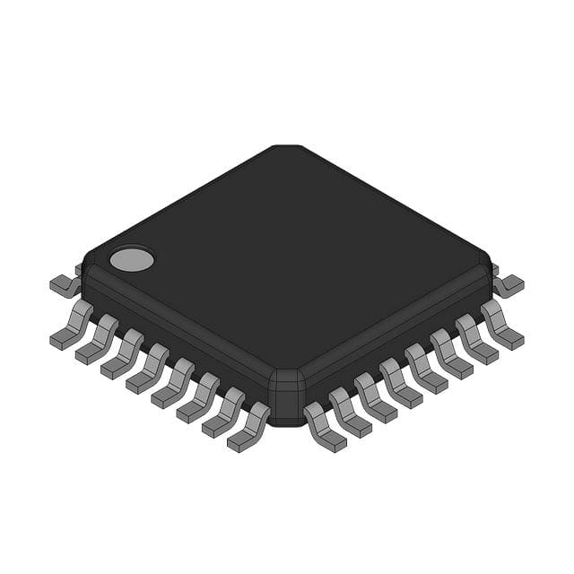
- Part No.:
- R5F212L2SDFP#U0
- Manufacturer:
- Renesas
- Category:
- Microcontrollers
- Package:
- 32-LQFP
- Datasheet:
-
 R5F212L2SDFP#U0.pdf
- Description:
- IC MCU 16BIT 8KB FLASH 32LQFP
- Quantity:
- Payment:

- Shipping:

Inventory:1,975
Please send an inquiry. Send us your inquiry, and we will respond immediately.
Product details
Overview
R5F212L2SDFP#U0 from Renesas Electronics is a 14-pin small-connector conversion adapter for the E1 emulator, enabling interface between 2.54-mm pitch cables and 1.27-mm pitch system connectors. It reduces PCB footprint by replacing standard headers with compact Samtec TFM-series connectors and supports both through-hole (TFM-107-01-L-D) and SMT (TFM-107-02-L-D) mounting. Its primary role is physical signal routing in embedded development environments during debug and programming.
For engineers reviewing the R5F212L2SDFP#U0 datasheet, R5F212L2SDFP#U0 pinout, R5F212L2SDFP#U0 application, or R5F212L2SDFP#U0 equivalent, key considerations include verified pin mapping between CN1 (E1 cable) and CN2 (user-system), mechanical height clearance limits (≤5 mm around connector), and compatibility with Renesas E1 emulator interface specifications.
Technical Context
The R5F212L2SDFP#U0 serves as a passive mechanical and electrical bridge - not an active IC - translating pin assignments between two standardized 14-pin interfaces. It implements non-standard pin remapping (e.g., CN1 Pin 2 → CN2 Pins 1 & 14; CN1 Pin 12 → CN2 Pins 1 & 14), requiring board-level design adaptation.
It is designed exclusively for use with the Renesas E1 emulator user-system interface cable (R0E000010KCE00) and mandates use of specified Samtec connectors: HTST-107-01-T-DV (upper), SFM-107-02-L-D-A (lower), and either TFM-107-01-L-D (DIP) or TFM-107-02-L-D (SMT) on the target system. Rated for 50 mating cycles per connector side.
Key Specifications
| Parameter | Value and Actual Design Meaning |
|---|---|
| Connector Type | Passive 14-pin conversion adapter - no active circuitry or power requirements. |
| Pitch Conversion | Converts 2.54 mm (CN1, E1 cable head) to 1.27 mm (CN2, user system) spacing. |
| Pin Count | 14-position interface on both sides; pin mapping is non-linear and explicitly defined in Table 3. |
| Mating Cycles | Guaranteed for ≥50 insertions/removals on both CN1 and CN2 sides. |
| Height Clearance | Requires ≤5 mm component height within 7.5 mm radius around mounted connector on user system. |
| Compliance | RoHS-compliant; certified under EU WEEE Directive 2002/96/EC. |
Availability
R5F212L2SDFP#U0 is available at Aetrix Electronics and suitable for embedded development, E1 emulator integration, and Renesas MCU debug infrastructure requiring stable component supply and traceable sourcing.
Supply support for R5F212L2SDFP#U0 includes scheduled delivery planning, volume procurement assistance, BOM continuity management, traceable sourcing, and lifecycle availability coordination for OEM customers, industrial embedded developers, connected-device designers, and electronics production programs.
Manufacturer
Renesas Electronics Corporation is a global semiconductor manufacturer specializing in microcontrollers, analog, power, and connectivity solutions for automotive, industrial, and enterprise applications.
The R5F212L2SDFP#U0 belongs to Renesas' tools and adapters product line, engineered specifically to extend the usability of the E1 emulator across space-constrained user-system designs while maintaining signal integrity and mechanical reliability.
FAQ
What is the function of the R5F212L2SDFP#U0?
The R5F212L2SDFP#U0 is a passive mechanical adapter that converts the 14-pin, 2.54-mm pitch connector on the E1 emulator interface cable to a 14-pin, 1.27-mm pitch connector compatible with compact user-system layouts. It contains no active components and performs only pin translation and physical spacing adaptation - the R5F212L2SDFP#U0 enables smaller PCB footprints without altering signal functionality.
Does the R5F212L2SDFP#U0 require power or configuration?
No, the R5F212L2SDFP#U0 is a fully passive adapter with no power pins, no firmware, and no configuration options. It operates solely as a wired interconnect - all signals pass through unchanged except for remapped pin positions. The R5F212L2SDFP#U0 relies entirely on correct mechanical mating and verified pin correspondence per Table 3 in its official user manual (R20UT0162EJ0200).
Which connectors are required to use the R5F212L2SDFP#U0?
The R5F212L2SDFP#U0 requires three specific Samtec connectors: HTST-107-01-T-DV (upper), SFM-107-02-L-D-A (lower), and either TFM-107-01-L-D (through-hole) or TFM-107-02-L-D (SMT) on the user system. These are mandatory for mechanical fit and electrical continuity - the R5F212L2SDFP#U0 will not function correctly with non-specified alternatives.
Is the R5F212L2SDFP#U0 compatible with other Renesas emulators like E2 or J-Link?
No, the R5F212L2SDFP#U0 is designed exclusively for the Renesas E1 emulator and its associated interface cable (R0E000010KCE00). It does not support E2, E2 Lite, or third-party debug probes. Pin mapping, mechanical dimensions, and orientation keys are specific to E1 - using the R5F212L2SDFP#U0 with other emulators may result in misalignment or signal mismatch.
What is the maximum allowable component height near the R5F212L2SDFP#U0 on the user system?
The R5F212L2SDFP#U0 imposes a strict mechanical constraint: components mounted within a 7.5 mm radius around the user-system connector must not exceed 5 mm in height. This ensures unobstructed mating with the adapter's lower connector (CN2). This limit applies only when using TFM-107-01-L-D or TFM-107-02-L-D - the R5F212L2SDFP#U0 documentation explicitly ties this specification to those Samtec part numbers.
R5F212L2SDFP#U0 Specifications
- Product attributes
- Attribute value
- Manufacturer:
- Renesas
- Package/Case:
- 32-LQFP
- Series:
- R8C/2x/2L
- Packaging:
- Bulk
- Product Status:
- Active
- Programmable:
- Not Verified
- Core Processor:
- R8C
- Core Size:
- 16-Bit
- Speed:
- 20MHz
- Connectivity:
- LINbus, SIO, UART/USART
- Peripherals:
- POR, PWM, Voltage Detect, WDT
- Number of I/O:
- 25
- Program Memory Size:
- 8KB (8K x 8)
- Program Memory Type:
- FLASH
- EEPROM Size:
- -
- RAM Size:
- 1K x 8
- Voltage - Supply (Vcc/Vdd):
- 2.2V ~ 5.5V
- Data Converters:
- A/D 9x10b
- Oscillator Type:
- Internal
- Operating Temperature:
- -40°C ~ 85°C (TA)
- Grade:
- -
- Qualification:
- -
- Mounting Type:
- Surface Mount
- Supplier Device Package:
R5F212L2SDFP#U0 FAQ
1.How can I place an order for R5F212L2SDFP#U0 through Aetrix?
Please submit a Request for Quotation (RFQ) for R5F212L2SDFP#U0 on Aetrix. Our sales agent will provide a competitive quotation and guide you through the order confirmation once you accept the terms.
2.Are the price and stock information for R5F212L2SDFP#U0 reliable?
The price and inventory of R5F212L2SDFP#U0 are updated periodically and may fluctuate due to market conditions. Stock and pricing data are typically refreshed every 24 hours. Quotation validity for R5F212L2SDFP#U0 is usually 5 days.
3.What payment methods are accepted for R5F212L2SDFP#U0?
We accept Wire Transfer, PayPal, Credit Card, Western Union, MoneyGram, and Escrow for R5F212L2SDFP#U0 transactions.
Note: Certain payment methods may incur a processing fee.
4.How is shipping managed for R5F212L2SDFP#U0?
R5F212L2SDFP#U0 orders can be shipped via leading logistics carriers, including DHL, UPS, FedEx, TNT, or Registered Mail.
Once your R5F212L2SDFP#U0 order is processed, you will receive an email with the shipment details and tracking number.
Note: Tracking information may take up to 24 hours to appear. Express delivery typically takes 3–5 business days.
5.How can I obtain technical support or documentation for R5F212L2SDFP#U0?
For technical support, including R5F212L2SDFP#U0 datasheets, pinout diagrams, or application guidance, please contact our engineering support team. They can provide detailed documentation and assistance for your R5F212L2SDFP#U0 requirements.
6.How does Aetrix verify that R5F212L2SDFP#U0 is sourced from the original manufacturer or authorized distributors?
All R5F212L2SDFP#U0 products on Aetrix are procured from qualified distributors and authorized channels. Our dedicated quality assurance team conducts strict verification, including traceability checks and, if necessary, third-party testing. This ensures that R5F212L2SDFP#U0 meets industry standards.
7.What is the process for return or replacement of R5F212L2SDFP#U0?
All R5F212L2SDFP#U0 units undergo pre-shipment inspection (PSI). If there is an issue with R5F212L2SDFP#U0, returns or replacements are accepted under the following conditions:
1.Quantity discrepancies, incorrect items, or visible external defects (such as breakage or corrosion), acknowledged by Aetrix.
2.The issue is reported within 90 days of delivery.
3.The R5F212L2SDFP#U0 part is unused and in its original packaging.
Return procedure for R5F212L2SDFP#U0:
1.Submit a request within 90 days.
2.Obtain a Return Material Authorization (RMA) from Aetrix.
R5F212L2SDFP#U0 Tags

-
ATTINY4-TSHR
Microchip Technology
-
ATTINY10-TSHR
Microchip Technology
-
ATTINY10-TS8R
Microchip Technology

-
ATTINY202-SSNR
Microchip Technology
-
ATTINY202-SSFR
Microchip Technology
-
ATTINY402-SSNR
Microchip Technology

-
PIC16F15213T-I/MF
Microchip Technology
-
PIC16F15213-E/MF
Microchip Technology

-
PIC10F200T-I/OT
Microchip Technology
-
ATTINY412-SSNR
Microchip Technology
-
PIC10F202T-I/OT
Microchip Technology

-
ATTINY404-SSNR
Microchip Technology
Tech Hub

TTL and CMOS logic families differ in thresholds, loading, output drive, power and timing. This engineering guide compares 74HC and 74HCT, calculates noise margins and checks 3.3 V/5 V compatibility.

A practical engineering guide to 3.3V and 5V logic compatibility, input thresholds, resistor dividers, translator ICs, MOSFET level shifting, I2C pull-ups, timing limits and power-sequencing risks.

The 74HC595 uses push-pull logic outputs, while the TPIC6B595 uses 50 V open-drain DMOS sinks for higher-power loads. This guide compares timing, current limits, 3.3 V interfacing, load wiring, thermal…

The 74HC595 converts serial data into eight stable parallel outputs. This guide covers pin functions, shift and storage timing, OE and MR behavior, drive-current limits, cascading, voltage compatibilit…

A technical comparison of level-sensitive latches and edge-triggered flip-flops, covering timing windows, setup and hold limits, master–slave operation, time borrowing, race-through, HDL inference and…

A D latch stores one bit while Enable controls when data can pass. This reference covers gate-level operation, truth tables, transparency, setup and hold timing, LE versus OE, common ICs and practical …

An SR latch stores one bit through cross-coupled feedback. This engineering reference covers NOR and NAND implementations, truth tables, forbidden-state recovery, gated operation, switch debouncing, fa…

Latch circuits retain one bit through feedback. This technical reference covers SR and D latches, truth tables, transparency, timing limits, latch-versus-flip-flop behavior, applications and common log…

An engineering guide to LED driver operation, constant-current and constant-voltage outputs, linear and switching topologies, dimming, IC selection, calculations, replacement compatibility, and fault c…

Operational amplifier guide covering op amp basics, feedback, ideal vs real op amps, common configurations, buffer circuits, offset, bias current, gain-bandwidth, slew rate, rail-to-rail limits and sel…


