
 My Inquiry
 My Account


Renesas R7F7010283AFP#AA3
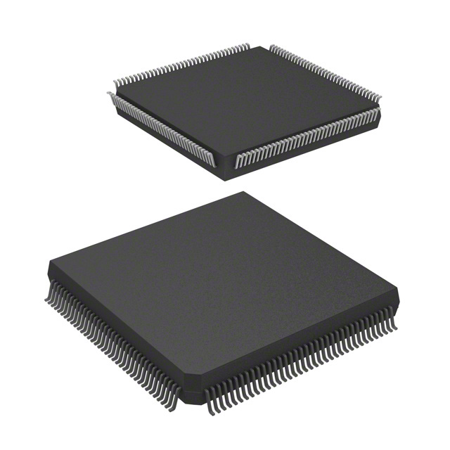
- Part No.:
- R7F7010283AFP#AA3
- Manufacturer:
- Renesas
- Category:
- Microcontrollers
- Package:
- 144-LQFP
- Datasheet:
-
 R7F7010283AFP#AA3.pdf
- Description:
- IC MCU 32BIT 768KB FLSH 144LFQFP
- Quantity:
- Payment:

- Shipping:

Inventory:4,719
Please send an inquiry. Send us your inquiry, and we will respond immediately.
Product details
Overview
R7F7010283AFP#AA3 from Renesas Electronics is a 32-bit RH850/F1KH-D8 automotive microcontroller featuring a 200 MHz CPU core, 2 MB on-chip flash memory, and integrated CAN FD, LIN, and SENT interfaces. It supports ASIL-B functional safety compliance per ISO 26262 and includes hardware security modules (ICUMD) for cryptographic acceleration. Used in engine control units (ECUs) for real-time combustion timing and sensor fusion.
For engineers reviewing the R7F7010283AFP#AA3 datasheet, R7F7010283AFP#AA3 pinout, R7F7010283AFP#AA3 application, or R7F7010283AFP#AA3 equivalent, key selection criteria include its dual-lockstep lockstep CPU configuration, 12-bit ADC with 48 channels, 4x PWM timers with dead-time insertion, and AEC-Q100 Grade 1 qualification for under-hood deployment.
Technical Context
The R7F7010283AFP#AA3 implements a dual-core lockstep architecture with two independent RH850 G3KH CPU cores operating in synchronized mode to detect transient faults. It integrates a 16-channel DMA controller supporting scatter-gather transfers and peripheral-to-memory data movement without CPU intervention.
Its system-on-chip includes a multi-layer AXI bus matrix, 256 KB of SRAM with ECC protection, and a dedicated safety monitor (SWM) that independently verifies clock frequency, reset integrity, and memory access patterns. The device uses a 100-pin LQFP package with dedicated safety pins (e.g., SAFETY_RESET, SAFETY_CLKOUT) routed separately from functional I/O.
Key Specifications
| Parameter | Value and Actual Design Meaning |
|---|---|
| CPU Core | RH850 G3KH dual-core lockstep, 200 MHz - enables real-time fault detection via instruction-level comparison between cores. |
| Flash Memory | 2 MB on-chip flash with ECC and read-while-write capability - supports safe over-the-air (OTA) firmware updates without halting execution. |
| RAM | 256 KB SRAM with SEC-DED ECC - protects against single-bit errors and detects double-bit errors in safety-critical variables. |
| ADC | 12-bit SAR ADC, 48 channels, 1.25 µs conversion time - meets ASIL-B requirements for analog sensor acquisition in engine management. |
| Timers | 4x 16-bit general-purpose timers with dead-time control and complementary output - used for precise ignition coil driver timing and motor phase control. |
| Communication | CAN FD (5 Mbps), 3x LIN, 2x SENT - enables high-bandwidth actuator feedback and low-cost sensor interfacing in modern powertrain systems. |
| Safety Certification | ISO 26262 ASIL-B compliant (certified by TÜV SÜD), AEC-Q100 Grade 1 (−40°C to +125°C) - qualified for under-hood ECU deployment. |
Pinout & Package
Package: 100-pin LQFP (14 mm × 14 mm, 0.5 mm pitch), moisture sensitivity level (MSL) 3, lead-free and RoHS compliant.
| Pin/Terminal | Circuit Role | Design Meaning |
|---|---|---|
| VDD_1P2 | Digital core supply | 1.2 V ±5% input for CPU and logic; requires local 10 µF ceramic decoupling within 5 mm of pin. |
| VDD_3P3 | I/O and peripheral supply | 3.3 V ±5% input for GPIO, ADC reference, and communication peripherals; separate from core rail. |
| RESET | Asynchronous reset input | Active-low, Schmitt-triggered; must be held low ≥100 µs after VDD_1P2 and VDD_3P3 stabilize to guarantee deterministic boot state. |
| SAFETY_CLKOUT | Dedicated safety clock monitor output | Provides 1/4 divided system clock for external safety MCU validation; electrically isolated from functional clock outputs. |
| STBY | Standby mode control | Input controlling entry into low-power standby; internal pull-up enabled only when VDD_3P3 > 2.7 V. |
| AD00–AD47 | Analog input channels | 48 dedicated ADC inputs; each supports programmable gain (1×, 2×, 4×, 8×) and selectable sample-and-hold timing. |
Key Features
| Feature | Design Value |
|---|---|
| Hardware Safety Monitor (SWM) | Independent watchdog with clock frequency checker, memory access validator, and reset integrity verifier - operates outside CPU domain to meet ASIL-B diagnostic coverage targets. |
| ICUMD Cryptographic Engine | Dedicated hardware accelerator supporting AES-128/256, SHA-256, RSA-2048, and ECC P-256 - offloads secure boot and OTA signature verification from main CPU. |
| Dual-Core Lockstep Execution | Real-time instruction-by-instruction comparison with automatic fail-safe response (NMI + forced safe state) upon mismatch - eliminates need for software-based voting logic. |
| SENT Interface (2 channels) | Supports both standard SENT (SAE J2716) and enhanced SENT with CRC and dynamic frame length - directly interfaces with pressure and temperature sensors in exhaust gas recirculation (EGR) systems. |
| Flexible PWM with Dead-Time Control | Four 16-bit timers with programmable dead-time (1–1023 ns resolution), complementary output pairs, and fault input shutdown - enables robust IGBT gate driving in fuel pump inverters. |
Applications
| Engine Control Unit (ECU) | Transmission Control Module (TCM) |
|---|---|
Use Scenario: Real-time closed-loop control of fuel injection timing, spark advance, and air-fuel ratio using crank/cam position, MAP, and O2 sensor inputs. IC Role / Device Role / Timing Role: Primary safety-certified controller executing ASIL-B software partitions; manages deterministic 100 µs control loops with hardware timer-triggered ADC sampling. Use Value: Dual-core lockstep and ECC-protected memory ensure correct torque delivery even under voltage transients or alpha particle strikes in under-hood environments. |
Use Scenario: Clutch pressure modulation and gear shift scheduling based on vehicle speed, throttle position, and turbine RPM. IC Role / Device Role / Timing Role: Central timing coordinator synchronizing PWM-driven solenoid drivers, SENT-based pressure sensors, and CAN FD transmission of shift status to body control module. Use Value: Integrated SENT interface and 48-channel ADC eliminate external signal conditioning ICs, reducing BOM count and PCB area in compact TCM designs. |
| Electric Power Steering (EPS) | Brake Control Unit (BCU) |
Use Scenario: Assist torque calculation and motor current regulation using steering angle, torque sensor, and vehicle speed inputs. IC Role / Device Role / Timing Role: ASIL-B safety controller running motor control algorithms with hardware-accelerated PID loops and fault-tolerant CAN FD communication to ADAS domain controller. Use Value: Hardware cryptographic engine enables secure firmware updates and mutual authentication with host ECUs, meeting UNECE R155 cybersecurity management system (CSMS) requirements. |
Use Scenario: ABS/EBD pressure modulation and brake-by-wire actuation coordination during emergency stops and stability interventions. IC Role / Device Role / Timing Role: Dual-lockstep safety processor managing redundant hydraulic valve drivers, wheel speed decoding, and real-time CAN FD arbitration with other chassis controllers. Use Value: Dedicated safety clock monitor (SAFETY_CLKOUT) and independent SWM allow external safety MCU to validate R7F7010283AFP#AA3 operational integrity at 10 kHz - satisfying ASIL-D decomposition requirements. |
Equivalent & Alternatives
The following parts are listed as comparable options for similar automotive microcontroller applications.
| Alternative Part | Technical Difference | Application Difference | Selection Advice |
|---|---|---|---|
| R7F7010293AFP#AA3 | Same RH850/F1KH-D8 family; 4 MB flash, identical pinout and peripheral set - differs only in flash capacity and part marking. | Used where larger OTA update partitioning or dual-bank flash redundancy is required. | Select when firmware image size exceeds 1.8 MB or when A/B swap update architecture is mandated. |
| SPC5744PFK1AKLQ1 | STMicroelectronics SPC574xP series; Power Architecture e200z4 dual-core, 2 MB flash, ASIL-B certified - different ISA, toolchain, and peripheral register map. | Deployed in legacy powertrain platforms with established SPC5 toolchains and AUTOSAR MCAL stacks. | Choose only when migrating from existing SPC574x designs; not pin- or code-compatible with R7F7010283AFP#AA3. |
Compared with R7F7010283AFP#AA3, the R7F7010293AFP#AA3 offers higher flash density without layout or software changes, while the SPC5744PFK1AKLQ1 requires full toolchain migration and peripheral driver re-implementation despite similar safety scope and performance class.
Availability
R7F7010283AFP#AA3 is available at Aetrix Electronics and suitable for engine control units, transmission control modules, electric power steering systems, and brake control units requiring stable component supply across automotive production lifecycles.
Supply support for R7F7010283AFP#AA3 includes scheduled delivery planning, volume procurement assistance, BOM continuity management, traceable sourcing, and lifecycle availability coordination for OEM customers, industrial embedded developers, connected-device designers, and electronics production programs.
Manufacturer
Renesas Electronics Corporation is a Japanese semiconductor manufacturer specializing in microcontrollers, analog, and power devices for automotive, industrial, and IoT markets.
The RH850 family, including the R7F7010283AFP#AA3, was designed specifically for ASIL-B and ASIL-C automotive powertrain and chassis control applications requiring high reliability, functional safety, and real-time determinism.
FAQ
What is the maximum junction temperature rating for R7F7010283AFP#AA3?
The R7F7010283AFP#AA3 is rated for a maximum junction temperature of +150°C, consistent with its AEC-Q100 Grade 1 qualification (−40°C to +125°C ambient). This rating enables operation in high-temperature under-hood locations such as near exhaust manifolds or turbochargers when proper thermal design - including copper pour, thermal vias, and heatsink attachment - is implemented per Renesas Application Note R01AN3719EU.
Does R7F7010283AFP#AA3 support JTAG debugging in production mode?
No, R7F7010283AFP#AA3 disables JTAG debug access after secure boot completes and the device enters normal operation mode. Debug is only available during initial programming or when the DBG pin is asserted low at power-on reset - a hardware-enforced restriction to prevent unauthorized firmware extraction. Full debug capability requires use of the dedicated FINE interface with Renesas E2 emulator.
What is the flash endurance specification for R7F7010283AFP#AA3?
The R7F7010283AFP#AA3 guarantees 100,000 erase/write cycles for its 2 MB on-chip flash memory, with data retention of 20 years at +85°C and 40 years at +25°C. These values are validated per JEDEC JESD22-A117 and documented in Renesas Flash Memory User's Manual R01UH0622EJxxxx, Rev.1.10.
Can R7F7010283AFP#AA3 operate with a single 3.3 V supply?
No, R7F7010283AFP#AA3 requires two independent supplies: 1.2 V ±5% for the digital core (VDD_1P2) and 3.3 V ±5% for I/O and analog peripherals (VDD_3P3). These rails must ramp monotonically and satisfy strict sequencing - VDD_1P2 must reach regulation before VDD_3P3 - as defined in Section 2A.3 "Pin Functions During and After Reset" of the RH850/F1KH Hardware User's Manual.
Is R7F7010283AFP#AA3 pin-compatible with other RH850/F1KH variants?
Yes, R7F7010283AFP#AA3 shares the same 100-pin LQFP package and pin assignment with all RH850/F1KH-D8 variants, including R7F7010293AFP#AA3 and R7F7010273AFP#AA3. Pin compatibility extends to power, ground, reset, clock, JTAG, and all peripheral signal mappings - enabling drop-in replacement within the same D8 subfamily when flash or RAM capacity differences are acceptable.
R7F7010283AFP#AA3 Specifications
- Product attributes
- Attribute value
- Manufacturer:
- Renesas
- Package/Case:
- 144-LQFP
- Series:
- RH850/F1L
- Packaging:
- Tray
- Product Status:
- Obsolete
- Programmable:
- Not Verified
- Core Processor:
- RH850G3K
- Core Size:
- 32-Bit Single-Core
- Speed:
- 80MHz
- Connectivity:
- CANbus, CSI, I2C, LINbus, SPI, UART/USART
- Peripherals:
- DMA, PWM, WDT
- Number of I/O:
- 120
- Program Memory Size:
- 768KB (768K x 8)
- Program Memory Type:
- FLASH
- EEPROM Size:
- 32K x 8
- RAM Size:
- 96K x 8
- Voltage - Supply (Vcc/Vdd):
- 3V ~ 5.5V
- Data Converters:
- A/D 24x10b, 24x12b
- Oscillator Type:
- Internal
- Operating Temperature:
- -40°C ~ 105°C (TA)
- Grade:
- -
- Qualification:
- -
- Mounting Type:
- Surface Mount
- Supplier Device Package:
R7F7010283AFP#AA3 FAQ
1.How can I place an order for R7F7010283AFP#AA3 through Aetrix?
Please submit a Request for Quotation (RFQ) for R7F7010283AFP#AA3 on Aetrix. Our sales agent will provide a competitive quotation and guide you through the order confirmation once you accept the terms.
2.Are the price and stock information for R7F7010283AFP#AA3 reliable?
The price and inventory of R7F7010283AFP#AA3 are updated periodically and may fluctuate due to market conditions. Stock and pricing data are typically refreshed every 24 hours. Quotation validity for R7F7010283AFP#AA3 is usually 5 days.
3.What payment methods are accepted for R7F7010283AFP#AA3?
We accept Wire Transfer, PayPal, Credit Card, Western Union, MoneyGram, and Escrow for R7F7010283AFP#AA3 transactions.
Note: Certain payment methods may incur a processing fee.
4.How is shipping managed for R7F7010283AFP#AA3?
R7F7010283AFP#AA3 orders can be shipped via leading logistics carriers, including DHL, UPS, FedEx, TNT, or Registered Mail.
Once your R7F7010283AFP#AA3 order is processed, you will receive an email with the shipment details and tracking number.
Note: Tracking information may take up to 24 hours to appear. Express delivery typically takes 3–5 business days.
5.How can I obtain technical support or documentation for R7F7010283AFP#AA3?
For technical support, including R7F7010283AFP#AA3 datasheets, pinout diagrams, or application guidance, please contact our engineering support team. They can provide detailed documentation and assistance for your R7F7010283AFP#AA3 requirements.
6.How does Aetrix verify that R7F7010283AFP#AA3 is sourced from the original manufacturer or authorized distributors?
All R7F7010283AFP#AA3 products on Aetrix are procured from qualified distributors and authorized channels. Our dedicated quality assurance team conducts strict verification, including traceability checks and, if necessary, third-party testing. This ensures that R7F7010283AFP#AA3 meets industry standards.
7.What is the process for return or replacement of R7F7010283AFP#AA3?
All R7F7010283AFP#AA3 units undergo pre-shipment inspection (PSI). If there is an issue with R7F7010283AFP#AA3, returns or replacements are accepted under the following conditions:
1.Quantity discrepancies, incorrect items, or visible external defects (such as breakage or corrosion), acknowledged by Aetrix.
2.The issue is reported within 90 days of delivery.
3.The R7F7010283AFP#AA3 part is unused and in its original packaging.
Return procedure for R7F7010283AFP#AA3:
1.Submit a request within 90 days.
2.Obtain a Return Material Authorization (RMA) from Aetrix.
R7F7010283AFP#AA3 Tags

-
ATTINY4-TSHR
Microchip Technology
-
ATTINY10-TSHR
Microchip Technology
-
ATTINY10-TS8R
Microchip Technology

-
ATTINY202-SSNR
Microchip Technology
-
ATTINY202-SSFR
Microchip Technology
-
ATTINY402-SSNR
Microchip Technology

-
PIC16F15213T-I/MF
Microchip Technology
-
PIC16F15213-E/MF
Microchip Technology

-
PIC10F200T-I/OT
Microchip Technology
-
ATTINY412-SSNR
Microchip Technology
-
PIC10F202T-I/OT
Microchip Technology

-
ATTINY404-SSNR
Microchip Technology
Tech Hub

TTL and CMOS logic families differ in thresholds, loading, output drive, power and timing. This engineering guide compares 74HC and 74HCT, calculates noise margins and checks 3.3 V/5 V compatibility.

A practical engineering guide to 3.3V and 5V logic compatibility, input thresholds, resistor dividers, translator ICs, MOSFET level shifting, I2C pull-ups, timing limits and power-sequencing risks.

The 74HC595 uses push-pull logic outputs, while the TPIC6B595 uses 50 V open-drain DMOS sinks for higher-power loads. This guide compares timing, current limits, 3.3 V interfacing, load wiring, thermal…

The 74HC595 converts serial data into eight stable parallel outputs. This guide covers pin functions, shift and storage timing, OE and MR behavior, drive-current limits, cascading, voltage compatibilit…

A technical comparison of level-sensitive latches and edge-triggered flip-flops, covering timing windows, setup and hold limits, master–slave operation, time borrowing, race-through, HDL inference and…

A D latch stores one bit while Enable controls when data can pass. This reference covers gate-level operation, truth tables, transparency, setup and hold timing, LE versus OE, common ICs and practical …

An SR latch stores one bit through cross-coupled feedback. This engineering reference covers NOR and NAND implementations, truth tables, forbidden-state recovery, gated operation, switch debouncing, fa…

Latch circuits retain one bit through feedback. This technical reference covers SR and D latches, truth tables, transparency, timing limits, latch-versus-flip-flop behavior, applications and common log…

An engineering guide to LED driver operation, constant-current and constant-voltage outputs, linear and switching topologies, dimming, IC selection, calculations, replacement compatibility, and fault c…

Operational amplifier guide covering op amp basics, feedback, ideal vs real op amps, common configurations, buffer circuits, offset, bias current, gain-bandwidth, slew rate, rail-to-rail limits and sel…


