
 My Inquiry
 My Account


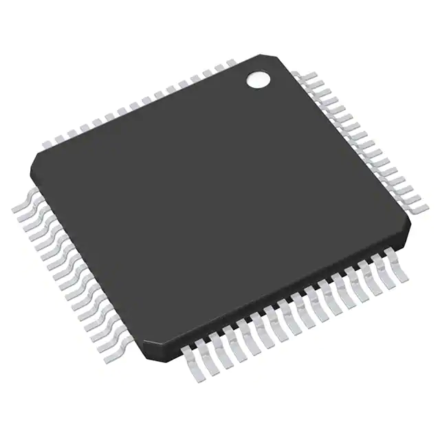
Renesas R7F7016904AFP-C#KA1
- Part No.:
- R7F7016904AFP-C#KA1
- Manufacturer:
- Renesas
- Category:
- Microcontrollers
- Package:
- 64-QFP
- Datasheet:
-
 R7F7016904AFP-C#KA1.pdf
- Description:
- IC MCU 32BIT 1MB FLASH 64LFQFP
- Quantity:
- Payment:

- Shipping:

Inventory:1,046
Please send an inquiry. Send us your inquiry, and we will respond immediately.
Product details
Overview
R7F7016904AFP-C#KA1 from Renesas Electronics is a 32-bit RH850/F1KH-D8 automotive microcontroller featuring dual-core lockstep CPU architecture, 4 MB on-chip flash memory, and ASIL-B compliance per ISO 26262 for safety-critical powertrain and chassis control applications. It integrates a 200 MHz core clock, 512 KB SRAM, and hardware-based cryptographic acceleration.
For engineers reviewing the R7F7016904AFP-C#KA1 datasheet, R7F7016904AFP-C#KA1 pinout, R7F7016904AFP-C#KA1 application, or R7F7016904AFP-C#KA1 equivalent, key selection criteria include dual-core lockstep execution integrity, integrated CAN FD (up to 5 channels), LIN support, and AEC-Q100 Grade 1 qualification for under-hood operation at −40°C to +125°C.
Technical Context
The R7F7016904AFP-C#KA1 implements two synchronized RH850 G3KH cores operating in lockstep mode with real-time comparison logic and error detection circuitry, enabling diagnostic coverage exceeding 90% for ASIL-B systems. It includes a dedicated Safety Support Core (SSC) for runtime monitoring of CPU, memory, and peripheral health.
Hardware safety features include ECC-protected 4 MB flash and 512 KB SRAM, lockstep-capable DMA controllers, and redundant watchdog timers with independent clock sources. The device supports functional safety development per ISO 26262 Part 5 & 6, with FMEDA reports and safety manuals available from Renesas.
Key Specifications
| Parameter | Value and Actual Design Meaning |
|---|---|
| CPU Core | Dual RH850 G3KH cores in lockstep configuration for fault-detection via real-time instruction and result comparison. |
| Max Clock Frequency | 200 MHz - enables deterministic real-time response for engine control and brake-by-wire timing budgets. |
| Flash Memory | 4 MB with ECC and read-while-write capability - supports safe over-the-air (OTA) firmware updates without interruption. |
| SRAM | 512 KB with ECC - provides protected data storage for safety-critical variables and stack operations. |
| Functional Safety | ISO 26262 ASIL-B compliant (certified), with integrated safety mechanisms including BIST, lockstep monitoring, and error signaling via FIT output. |
| Automotive Qualification | AEC-Q100 Grade 1 (−40°C to +125°C ambient) - qualified for under-hood powertrain and chassis ECU deployment. |
| Communication Interfaces | 5× CAN FD (up to 5 Mbps), 3× LIN, 2× FlexRay (v2.1A), 1× SENT - meets full vehicle network requirements for modern ECUs. |
Pinout & Package
Package: 176-pin LQFP (24 mm × 24 mm, 0.5 mm pitch), moisture sensitivity level (MSL) 3, RoHS-compliant, lead-free.
| Pin/Terminal | Circuit Role | Design Meaning |
|---|---|---|
| VDD_MAIN (Pins 1–4, 173–176) | Main power supply (3.3 V) | Supplies core logic and most peripherals; requires low-noise decoupling per Renesas layout guidelines. |
| VDD_IO (Pins 5–8, 170–172) | I/O power supply (3.3 V) | Independent rail for GPIOs and communication interfaces; allows voltage domain isolation from core logic. |
| RESET# (Pin 10) | Active-low reset input | Asynchronous external reset signal; synchronous deassertion required for safe lockstep initialization sequence. |
| CLKIN (Pins 12–13) | External crystal oscillator input | Supports 8–20 MHz crystal; feeds PLL for internal 200 MHz system clock generation with jitter tolerance ≤ ±50 ppm. |
| CAN0_TX / CAN0_RX (Pins 22–23) | CAN FD channel 0 differential I/O | Direct connection to CAN transceiver; supports bit rates up to 5 Mbps with built-in loopback and self-test modes. |
| FSI0_CLK / FSI0_DATA (Pins 34–35) | Functional Safety Interface clock/data | Used for inter-ECU safety status exchange; operates at 10 MHz with CRC-16 protection and timeout detection. |
Key Features
| Feature | Design Value |
|---|---|
| Dual-core lockstep execution | Real-time instruction and result comparison between two identical cores, with automatic fail-safe shutdown on mismatch. |
| Integrated Safety Support Core (SSC) | Dedicated RISC-V-based monitor core that independently validates CPU, memory, and peripheral operation without software overhead. |
| ECC-protected memory subsystem | Single-bit error correction and double-bit error detection on all 4 MB flash and 512 KB SRAM - prevents silent data corruption. |
| Hardware cryptographic accelerator | Supports AES-128/256, SHA-256, RSA-2048, and ECC NIST P-256 - accelerates secure boot and OTA authentication. |
| Redundant watchdog timers | Two independent watchdogs (WDT and SWDT) with separate clock domains and reset outputs - eliminates single-point failure. |
Applications
| Engine Control Unit (ECU) | Electric Power Steering (EPS) |
|---|---|
|
Use Scenario: Real-time combustion timing, fuel injection, and knock control in gasoline/diesel engines. IC Role / Device Role / Timing Role: Primary ASIL-B controller executing safety-critical engine management tasks with dual-core lockstep validation. Use Value: Enables deterministic sub-microsecond interrupt latency and certified fault coverage for ISO 26262-compliant engine control software. |
Use Scenario: Torque assist calculation, motor position feedback processing, and fail-safe torque reduction during sensor faults. IC Role / Device Role / Timing Role: Safety-certified host MCU managing EPS motor control loop and ASIL-D decomposition via hardware redundancy. Use Value: Delivers <10 µs worst-case interrupt response time and hardware-enforced separation between safety and non-safety software partitions. |
| Brake-by-Wire System | Advanced Driver Assistance (ADAS) Domain Controller |
|
Use Scenario: Hydraulic pressure modulation, wheel speed fusion, and emergency braking actuation with redundancy. IC Role / Device Role / Timing Role: Dual-lockstep controller interfacing with ABS/ESC sensors and actuators while maintaining ASIL-B integrity. Use Value: Provides certified diagnostic coverage >92% for brake control functions and supports seamless integration with FlexRay backbone networks. |
Use Scenario: Sensor preprocessing (camera/radar), path planning coordination, and fail-operational handover to backup ECU. IC Role / Device Role / Timing Role: High-integrity safety monitor co-processor validating primary ADAS SoC outputs and triggering fallback states. Use Value: Offers hardware-isolated safety channel (FSI interface) and deterministic response to critical fault signals within 200 ns. |
Equivalent & Alternatives
The following parts are listed as comparable options for similar automotive safety microcontroller applications.
| Alternative Part | Technical Difference | Application Difference | Selection Advice |
|---|---|---|---|
| R7F7016894AFP-C#KA1 | Same RH850/F1KH-D8 family, but with 2 MB flash and 256 KB SRAM; identical pinout and safety architecture. | Suitable for cost-optimized ASIL-B modules where firmware footprint is ≤2 MB and RAM usage ≤256 KB. | Select when full 4 MB flash is unnecessary and BOM cost reduction is prioritized without sacrificing safety certification or pin compatibility. |
| SPC574S54E3 | STMicroelectronics SPC574S series; dual Power Architecture e200z4 cores, 2 MB flash, ASIL-B certified, but no integrated FSI interface. | Lacks native functional safety inter-ECU interface; requires external protocol translation for safety status exchange. | Choose when leveraging existing SPC5 toolchain and legacy software investment, accepting added design complexity for cross-ECU safety signaling. |
Compared with R7F7016904AFP-C#KA1, the R7F7016894AFP-C#KA1 offers identical safety architecture and pinout at reduced memory capacity, while the SPC574S54E3 delivers comparable ASIL-B capability but lacks integrated FSI-requiring external logic for safety-critical inter-ECU communication.
Availability
R7F7016904AFP-C#KA1 is available at Aetrix Electronics and suitable for engine control units, electric power steering systems, and brake-by-wire modules requiring stable component supply across automotive production lifecycles.
Supply support for R7F7016904AFP-C#KA1 includes scheduled delivery planning, volume procurement assistance, BOM continuity management, traceable sourcing, and lifecycle availability coordination for OEM customers, industrial embedded developers, connected-device designers, and electronics production programs.
Manufacturer
Renesas Electronics Corporation is a global semiconductor manufacturer headquartered in Tokyo, Japan, specializing in microcontrollers, analog, power, and SoC solutions for automotive, industrial, and IoT markets.
The RH850 family-including R7F7016904AFP-C#KA1-is engineered specifically for ASIL-B and ASIL-D automotive applications, with emphasis on functional safety, real-time determinism, and high-temperature reliability in powertrain and chassis control systems.
FAQ
What is the maximum junction temperature rating for the R7F7016904AFP-C#KA1?
The R7F7016904AFP-C#KA1 is rated for operation up to +150°C junction temperature, consistent with its AEC-Q100 Grade 1 qualification (−40°C to +125°C ambient). This thermal margin enables reliable deployment in high-power-density engine control modules where PCB-level heat dissipation is constrained. Thermal design must maintain TJ ≤ 150°C under worst-case load conditions per Renesas' thermal resistance specifications in the datasheet.
Does the R7F7016904AFP-C#KA1 support JTAG debugging in lockstep mode?
Yes, the R7F7016904AFP-C#KA1 supports full JTAG debugging via the dedicated JTAG port (TCK/TMS/TDI/TDO pins), including visibility into both lockstep cores simultaneously. Debug access remains enabled during lockstep operation, allowing real-time register inspection and breakpoint setting without disabling safety monitoring. However, debug entry triggers a controlled safety state transition per ISO 26262 requirements.
How many CAN FD channels does the R7F7016904AFP-C#KA1 integrate, and what is their maximum bit rate?
The R7F7016904AFP-C#KA1 integrates five fully independent CAN FD controllers, each supporting bit rates up to 5 Mbps in FD mode and 1 Mbps in classical CAN mode. All channels feature hardware message filtering, transmit/receive FIFOs, and built-in loopback testing-enabling concurrent high-speed communication with powertrain, chassis, and body domain ECUs without software arbitration overhead.
Is the R7F7016904AFP-C#KA1 pin-compatible with other RH850/F1KH-D8 variants?
Yes, the R7F7016904AFP-C#KA1 shares identical 176-pin LQFP mechanical and electrical pinout with all RH850/F1KH-D8 family members, including R7F7016894AFP-C#KA1 and R7F7016914AFP-C#KA1. Pin assignments for power, reset, clocks, and peripheral I/O are fixed across the family, enabling hardware reuse across memory- and feature-scaled variants without PCB redesign.
What safety documentation is provided by Renesas for the R7F7016904AFP-C#KA1?
Renesas provides comprehensive ISO 26262-compliant safety documentation for the R7F7016904AFP-C#KA1, including the Safety Manual, FMEDA report (FIT rate, diagnostic coverage), safety analysis summary, and hardware/software interface specification (HSIS). These documents are delivered under NDA and support ASIL-B system integration in certified automotive development workflows.
R7F7016904AFP-C#KA1 Specifications
- Product attributes
- Attribute value
- Manufacturer:
- Renesas
- Package/Case:
- 64-QFP
- Series:
- RH850/F1KM-S1
- Packaging:
- Tape & Reel (TR)
- Product Status:
- Active
- Programmable:
- Not Verified
- Core Processor:
- RH850G3KH
- Core Size:
- 32-Bit Single-Core
- Speed:
- 120MHz
- Connectivity:
- CANbus, CSI, I2C, LINbus, SPI, UART/USART
- Peripherals:
- DMA, PWM, WDT
- Number of I/O:
- 49
- Program Memory Size:
- 1MB (1M x 8)
- Program Memory Type:
- FLASH
- EEPROM Size:
- 64K x 8
- RAM Size:
- 128K x 8
- Voltage - Supply (Vcc/Vdd):
- 3V ~ 5.5V
- Data Converters:
- A/D 10x10b, 11x12b
- Oscillator Type:
- Internal
- Operating Temperature:
- -40°C ~ 125°C (TA)
- Grade:
- Automotive
- Qualification:
- AEC-Q100
- Mounting Type:
- Surface Mount
- Supplier Device Package:
R7F7016904AFP-C#KA1 FAQ
1.How can I place an order for R7F7016904AFP-C#KA1 through Aetrix?
Please submit a Request for Quotation (RFQ) for R7F7016904AFP-C#KA1 on Aetrix. Our sales agent will provide a competitive quotation and guide you through the order confirmation once you accept the terms.
2.Are the price and stock information for R7F7016904AFP-C#KA1 reliable?
The price and inventory of R7F7016904AFP-C#KA1 are updated periodically and may fluctuate due to market conditions. Stock and pricing data are typically refreshed every 24 hours. Quotation validity for R7F7016904AFP-C#KA1 is usually 5 days.
3.What payment methods are accepted for R7F7016904AFP-C#KA1?
We accept Wire Transfer, PayPal, Credit Card, Western Union, MoneyGram, and Escrow for R7F7016904AFP-C#KA1 transactions.
Note: Certain payment methods may incur a processing fee.
4.How is shipping managed for R7F7016904AFP-C#KA1?
R7F7016904AFP-C#KA1 orders can be shipped via leading logistics carriers, including DHL, UPS, FedEx, TNT, or Registered Mail.
Once your R7F7016904AFP-C#KA1 order is processed, you will receive an email with the shipment details and tracking number.
Note: Tracking information may take up to 24 hours to appear. Express delivery typically takes 3–5 business days.
5.How can I obtain technical support or documentation for R7F7016904AFP-C#KA1?
For technical support, including R7F7016904AFP-C#KA1 datasheets, pinout diagrams, or application guidance, please contact our engineering support team. They can provide detailed documentation and assistance for your R7F7016904AFP-C#KA1 requirements.
6.How does Aetrix verify that R7F7016904AFP-C#KA1 is sourced from the original manufacturer or authorized distributors?
All R7F7016904AFP-C#KA1 products on Aetrix are procured from qualified distributors and authorized channels. Our dedicated quality assurance team conducts strict verification, including traceability checks and, if necessary, third-party testing. This ensures that R7F7016904AFP-C#KA1 meets industry standards.
7.What is the process for return or replacement of R7F7016904AFP-C#KA1?
All R7F7016904AFP-C#KA1 units undergo pre-shipment inspection (PSI). If there is an issue with R7F7016904AFP-C#KA1, returns or replacements are accepted under the following conditions:
1.Quantity discrepancies, incorrect items, or visible external defects (such as breakage or corrosion), acknowledged by Aetrix.
2.The issue is reported within 90 days of delivery.
3.The R7F7016904AFP-C#KA1 part is unused and in its original packaging.
Return procedure for R7F7016904AFP-C#KA1:
1.Submit a request within 90 days.
2.Obtain a Return Material Authorization (RMA) from Aetrix.
R7F7016904AFP-C#KA1 Tags

-
ATTINY4-TSHR
Microchip Technology
-
ATTINY10-TSHR
Microchip Technology
-
ATTINY10-TS8R
Microchip Technology

-
ATTINY202-SSNR
Microchip Technology
-
ATTINY202-SSFR
Microchip Technology
-
ATTINY402-SSNR
Microchip Technology

-
PIC16F15213T-I/MF
Microchip Technology
-
PIC16F15213-E/MF
Microchip Technology

-
PIC10F200T-I/OT
Microchip Technology
-
ATTINY412-SSNR
Microchip Technology
-
PIC10F202T-I/OT
Microchip Technology

-
ATTINY404-SSNR
Microchip Technology
Tech Hub

A practical engineering and sourcing framework covering lifecycle verification, lifetime-buy calculations, replacement qualification, supplier checks and counterfeit-risk controls.

TTL and CMOS logic families differ in thresholds, loading, output drive, power and timing. This engineering guide compares 74HC and 74HCT, calculates noise margins and checks 3.3 V/5 V compatibility.

A practical engineering guide to 3.3V and 5V logic compatibility, input thresholds, resistor dividers, translator ICs, MOSFET level shifting, I2C pull-ups, timing limits and power-sequencing risks.

The 74HC595 uses push-pull logic outputs, while the TPIC6B595 uses 50 V open-drain DMOS sinks for higher-power loads. This guide compares timing, current limits, 3.3 V interfacing, load wiring, thermal…

The 74HC595 converts serial data into eight stable parallel outputs. This guide covers pin functions, shift and storage timing, OE and MR behavior, drive-current limits, cascading, voltage compatibilit…

A technical comparison of level-sensitive latches and edge-triggered flip-flops, covering timing windows, setup and hold limits, master–slave operation, time borrowing, race-through, HDL inference and…

A D latch stores one bit while Enable controls when data can pass. This reference covers gate-level operation, truth tables, transparency, setup and hold timing, LE versus OE, common ICs and practical …

An SR latch stores one bit through cross-coupled feedback. This engineering reference covers NOR and NAND implementations, truth tables, forbidden-state recovery, gated operation, switch debouncing, fa…

Latch circuits retain one bit through feedback. This technical reference covers SR and D latches, truth tables, transparency, timing limits, latch-versus-flip-flop behavior, applications and common log…

An engineering guide to LED driver operation, constant-current and constant-voltage outputs, linear and switching topologies, dimming, IC selection, calculations, replacement compatibility, and fault c…


