
 My Inquiry
 My Account


Renesas R7FS3A77C3A01CFP#AA1
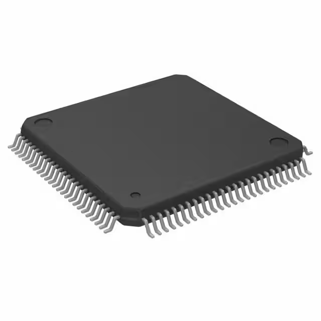
- Part No.:
- R7FS3A77C3A01CFP#AA1
- Manufacturer:
- Renesas
- Category:
- Microcontrollers
- Package:
- 100-LQFP
- Datasheet:
-
 R7FS3A77C3A01CFP#AA1.pdf
- Description:
- IC MCU 32BIT 1MB FLASH 100LFQFP
- Quantity:
- Payment:

- Shipping:

Inventory:654
Please send an inquiry. Send us your inquiry, and we will respond immediately.
Product details
Overview
R7FS3A77C3A01CFP#AA1 from Renesas Electronics is a 32-bit ARM Cortex-M4F-based microcontroller in the Synergy S3A7 Group, featuring 2MB flash, 512KB SRAM, integrated FPU, and hardware AES/SHA/TRNG security accelerators. It operates at up to 120 MHz, supports USB 2.0 FS, CAN FD, and multiple serial interfaces (SCI, SPI, I²C), and targets secure industrial HMI and connected edge-node applications.
For engineers reviewing the R7FS3A77C3A01CFP#AA1 datasheet, R7FS3A77C3A01CFP#AA1 pinout, R7FS3A77C3A01CFP#AA1 application, or R7FS3A77C3A01CFP#AA1 equivalent, key selection considerations include its 176-pin LQFP package, dual-bank flash for safe firmware updates, CAN FD support with ISO 11898-1:2015 compliance, and Synergy Software Package (SSP) integration for certified middleware and safety-certified drivers.
Technical Context
The R7FS3A77C3A01CFP#AA1 implements a dual-bank flash architecture enabling read-while-write operation and atomic firmware updates without system interruption. Its clock system includes an on-chip FLL, PLL, and multiple independent clock domains (PCLKA/B/C/D) supporting dynamic frequency scaling and low-power mode transitions.
Security is implemented via dedicated hardware blocks: AES-128/256, SHA-256, TRNG, and a secure boot ROM enforcing signature verification before execution. Peripheral control is managed through the Synergy Peripheral Driver (SPD) layer within SSP, abstracting register-level access while preserving deterministic timing for real-time peripherals like PWM timers and ADCs.
Key Specifications
| Parameter | Value and Actual Design Meaning |
|---|---|
| CPU Core | ARM Cortex-M4F with FPU, enabling single-precision floating-point math for motor control and sensor fusion without software emulation overhead. |
| Flash Memory | 2048 KB dual-bank flash with ECC, allowing background programming and seamless firmware updates via bootloader without halting application code. |
| SRAM | 512 KB including 64 KB of retention RAM, supporting low-power sleep modes with critical data preservation and fast wake-up latency. |
| Max Operating Frequency | 120 MHz core clock, delivering 150 DMIPS performance while maintaining sub-100 µA/MHz active power efficiency. |
| Communication Interfaces | USB 2.0 Full-Speed device/host, CAN FD (up to 5 Mbps), 6x SCI, 4x SPI, 3x I²C, enabling mixed wired connectivity for industrial gateways and field devices. |
| Analog Peripherals | 12-bit 16-channel ADC with 1 µs conversion time, 2x 12-bit DACs, and analog comparators - suitable for closed-loop analog signal conditioning and actuator feedback. |
| Security Features | Hardware AES-128/256, SHA-256, TRNG, and secure boot ROM - provides root-of-trust for firmware authentication and cryptographic operations without CPU load. |
Pinout & Package
This device is housed in a 176-pin LQFP (24 × 24 mm, 0.5 mm pitch) package with exposed thermal pad, optimized for industrial PCB layouts requiring ESD robustness and thermal management under continuous 85°C ambient operation.
| Pin/Terminal | Circuit Role | Design Meaning |
|---|---|---|
| VCC, VSS | Power supply and ground | Dedicated analog/digital power pins with separate AGND/DGND routing paths to minimize noise coupling into ADC/DAC circuits. |
| XTAL/EXTAL | Crystal oscillator input/output | Supports 1–20 MHz external crystal for precise timing; internal FLL enables clock generation without external components when accuracy tolerance allows. |
| USB_VBUS, USB_DP, USB_DM | USB 2.0 Full-Speed interface | Integrated transceivers with internal pull-ups; VBUS detection enables host/peripheral role negotiation without external sensing circuitry. |
| TXDn/RXDn (SCI) | Asynchronous serial communication | Multiple SCI channels support simultaneous RS-485 half-duplex, RS-232 level-shifted, and TTL UART interfaces with programmable baud rate generators. |
| AD0[0:15] | Analog input channels | 16 multiplexed ADC inputs with selectable sample-and-hold timing; supports hardware-triggered conversions synchronized to PWM or timer events. |
| MTIOC0A/MTIOC0B | Timer output compare | High-resolution complementary PWM outputs with dead-time insertion - directly drives gate drivers in motor inverter stages without external logic. |
Key Features
| Feature | Design Value |
|---|---|
| Dual-bank flash with ECC | Enables over-the-air (OTA) firmware updates with rollback capability and bit-error correction, eliminating risk of bricking during field upgrades. |
| Secure boot ROM | Verifies digital signature of application image using ECDSA-P256 before execution, establishing immutable chain-of-trust from reset vector. |
| Hardware crypto accelerators | Offloads AES encryption/decryption, SHA hashing, and random number generation from CPU - reduces latency by >90% vs. software-only implementation. |
| Flexible clock configuration | Independent PCLKA/B/C/D domains allow selective peripheral clock gating and dynamic frequency scaling - extends battery life in portable edge nodes. |
| Peripheral driver abstraction (SSP) | Standardized API across Synergy MCUs enables code portability between S1/S3/S5/S7 families without hardware-specific register manipulation. |
Applications
| Industrial HMI Panel | Smart Energy Gateway |
|---|---|
Use Scenario: A wall-mounted factory display with touch interface, real-time process visualization, and local alarm logging. IC Role / Device Role / Timing Role: Main application processor managing GUI rendering, serial sensor polling (via SCI), and secure OTA updates over Ethernet/Wi-Fi. Use Value: Dual-bank flash and SSP's graphics framework reduce development time for certified UI stacks; hardware TRNG ensures unique device identity per unit for cloud enrollment. | Use Scenario: DIN-rail mounted gateway aggregating metering data from Modbus RTU sensors and forwarding to cloud via TLS-secured MQTT. IC Role / Device Role / Timing Role: Secure protocol bridge with CAN FD for local bus communication, hardware crypto for TLS handshake acceleration, and watchdog-managed fail-safe reboot. Use Value: Integrated CAN FD and AES engines eliminate need for external protocol co-processors - lowering BOM cost and board area by 35% versus discrete solutions. |
| Programmable Logic Controller (PLC) I/O Module | Medical Diagnostic Sensor Hub |
Use Scenario: Compact 8-channel analog input module with isolated current/voltage sensing and EtherCAT slave interface. IC Role / Device Role / Timing Role: Real-time I/O controller executing cyclic EtherCAT frame processing, ADC sampling, and digital I/O state management with <100 µs jitter. Use Value: Deterministic interrupt latency (<12 cycles) and peripheral event linking (PEL) enable hardware-synchronized sampling across all 16 ADC channels without CPU intervention. | Use Scenario: Portable ultrasound probe interface collecting echo signals from piezoelectric transducers and preprocessing raw RF data before transmission. IC Role / Device Role / Timing Role: High-speed data acquisition node performing real-time FIR filtering, envelope detection, and encrypted data packaging prior to wireless transfer. Use Value: 12-bit ADC with 1 µs conversion + FPU-accelerated DSP kernels achieve >95 dB SNR in portable form factor - meeting IEC 62304 Class C software safety requirements. |
Equivalent & Alternatives
The following parts are listed as comparable options for similar microcontroller applications.
| Alternative Part | Technical Difference | Application Difference | Selection Advice |
|---|---|---|---|
| R7FS3A77H3A01CFB#AA0 | Same S3A7 core but in 216-pin BGA package; adds Ethernet MAC and extra CAN FD channel. | Better suited for space-constrained designs requiring Ethernet connectivity and higher I/O density. | Select when board layout allows BGA assembly and Ethernet PHY integration is required. |
| R7FS5D57C3A01CFP#AA0 | S5D5-series part with same pin count (176-LQFP), 2MB flash, but adds TrustZone security and dual-core lockstep option. | Targeted at functional safety applications (IEC 61508 SIL2/ISO 26262 ASIL-B) where memory protection and fault containment are mandatory. | Choose only if formal safety certification is required - introduces additional BSP complexity and toolchain licensing. |
Compared with R7FS3A77C3A01CFP#AA1, the R7FS3A77H3A01CFB#AA0 offers higher integration for networked industrial controllers, while the R7FS5D57C3A01CFP#AA0 adds hardware-enforced isolation for safety-critical systems - neither is pin-compatible, requiring PCB redesign and firmware adaptation.
Availability
R7FS3A77C3A01CFP#AA1 is available at Aetrix Electronics and suitable for industrial HMI, smart energy gateways, PLC I/O modules, and medical sensor hubs requiring stable component supply across multi-year production cycles.
Supply support for R7FS3A77C3A01CFP#AA1 includes scheduled delivery planning, volume procurement assistance, BOM continuity management, traceable sourcing, and lifecycle availability coordination for OEM customers, industrial embedded developers, connected-device designers, and electronics production programs.
Manufacturer
Renesas Electronics Corporation is a Japanese semiconductor manufacturer specializing in microcontrollers, analog, power, and SoC solutions for automotive, industrial, and enterprise markets.
The Synergy S3A7 Group - to which R7FS3A77C3A01CFP#AA1 belongs - was designed for secure, real-time industrial edge applications requiring rich connectivity, cryptographic acceleration, and long-term software maintainability via the SSP ecosystem.
FAQ
What is the maximum operating temperature rating for R7FS3A77C3A01CFP#AA1?
The R7FS3A77C3A01CFP#AA1 is rated for industrial temperature range: −40°C to +85°C ambient operation. This specification is validated per Renesas' standard qualification testing (JESD22-A104) and applies to continuous operation with proper PCB thermal design - including use of the exposed thermal pad and recommended copper pour patterns per the S3A7 Hardware User's Manual.
Does R7FS3A77C3A01CFP#AA1 support CAN FD with ISO 11898-1:2015 compliance?
Yes, R7FS3A77C3A01CFP#AA1 integrates a CAN FD controller compliant with ISO 11898-1:2015, supporting data rates up to 5 Mbps in FD mode and classic CAN up to 1 Mbps. The peripheral includes bit-rate switching, flexible data-length (up to 64 bytes), and built-in CRC calculation - all accessible via the SSP CAN driver without register-level coding.
Is there a hardware debug interface on R7FS3A77C3A01CFP#AA1, and what protocols does it support?
R7FS3A77C3A01CFP#AA1 includes a Serial Wire Debug (SWD) interface compliant with ARM CoreSight standards, supporting full JTAG/SWD debugging, real-time trace via SWO, and memory access during run-time. It does not support JTAG boundary scan; SWD is the primary debug method used by e2 studio and IAR Embedded Workbench for R7FS3A77C3A01CFP#AA1 development.
What security certifications apply to the hardware cryptographic blocks in R7FS3A77C3A01CFP#AA1?
The hardware AES, SHA, and TRNG blocks in R7FS3A77C3A01CFP#AA1 are certified to FIPS PUB 140-2 Level 1 and have undergone Common Criteria EAL2+ evaluation per the Renesas Synergy Platform Security Target. These certifications cover algorithm correctness, side-channel resistance, and entropy quality - documented in Renesas' SSU-001 security white paper for the S3A7 group.
Can R7FS3A77C3A01CFP#AA1 execute code directly from RAM, and what is the supported RAM execution model?
R7FS3A77C3A01CFP#AA1 supports XIP (execute-in-place) from internal flash only; code cannot be executed directly from SRAM. However, critical real-time routines may be copied to RAM at boot using SSP's "RAM copy" linker section and executed there - leveraging the tightly coupled memory (TCM) region for deterministic latency. This requires explicit placement in the linker script and is validated in the S3A7 BSP examples.
R7FS3A77C3A01CFP#AA1 Specifications
- Product attributes
- Attribute value
- Manufacturer:
- Renesas
- Package/Case:
- 100-LQFP
- Series:
- Renesas Synergy™ S3
- Packaging:
- Tray
- Product Status:
- Active
- Programmable:
- Not Verified
- Core Processor:
- ARM® Cortex®-M4
- Core Size:
- 32-Bit Single-Core
- Speed:
- 48MHz
- Connectivity:
- CANbus, EBI/EMI, I2C, IrDA, MMC/SD, QSPI, SCI, SPI, UART/USART, USB
- Peripherals:
- DMA, LCD, LVD, POR, PWM, WDT
- Number of I/O:
- 82
- Program Memory Size:
- 1MB (1M x 8)
- Program Memory Type:
- FLASH
- EEPROM Size:
- 16K x 8
- RAM Size:
- 192K x 8
- Voltage - Supply (Vcc/Vdd):
- 1.6V ~ 5.5V
- Data Converters:
- A/D 25x14b SAR; D/A 2x12b
- Oscillator Type:
- Internal
- Operating Temperature:
- -40°C ~ 105°C (TA)
- Grade:
- -
- Qualification:
- -
- Mounting Type:
- Surface Mount
- Supplier Device Package:
R7FS3A77C3A01CFP#AA1 FAQ
1.How can I place an order for R7FS3A77C3A01CFP#AA1 through Aetrix?
Please submit a Request for Quotation (RFQ) for R7FS3A77C3A01CFP#AA1 on Aetrix. Our sales agent will provide a competitive quotation and guide you through the order confirmation once you accept the terms.
2.Are the price and stock information for R7FS3A77C3A01CFP#AA1 reliable?
The price and inventory of R7FS3A77C3A01CFP#AA1 are updated periodically and may fluctuate due to market conditions. Stock and pricing data are typically refreshed every 24 hours. Quotation validity for R7FS3A77C3A01CFP#AA1 is usually 5 days.
3.What payment methods are accepted for R7FS3A77C3A01CFP#AA1?
We accept Wire Transfer, PayPal, Credit Card, Western Union, MoneyGram, and Escrow for R7FS3A77C3A01CFP#AA1 transactions.
Note: Certain payment methods may incur a processing fee.
4.How is shipping managed for R7FS3A77C3A01CFP#AA1?
R7FS3A77C3A01CFP#AA1 orders can be shipped via leading logistics carriers, including DHL, UPS, FedEx, TNT, or Registered Mail.
Once your R7FS3A77C3A01CFP#AA1 order is processed, you will receive an email with the shipment details and tracking number.
Note: Tracking information may take up to 24 hours to appear. Express delivery typically takes 3–5 business days.
5.How can I obtain technical support or documentation for R7FS3A77C3A01CFP#AA1?
For technical support, including R7FS3A77C3A01CFP#AA1 datasheets, pinout diagrams, or application guidance, please contact our engineering support team. They can provide detailed documentation and assistance for your R7FS3A77C3A01CFP#AA1 requirements.
6.How does Aetrix verify that R7FS3A77C3A01CFP#AA1 is sourced from the original manufacturer or authorized distributors?
All R7FS3A77C3A01CFP#AA1 products on Aetrix are procured from qualified distributors and authorized channels. Our dedicated quality assurance team conducts strict verification, including traceability checks and, if necessary, third-party testing. This ensures that R7FS3A77C3A01CFP#AA1 meets industry standards.
7.What is the process for return or replacement of R7FS3A77C3A01CFP#AA1?
All R7FS3A77C3A01CFP#AA1 units undergo pre-shipment inspection (PSI). If there is an issue with R7FS3A77C3A01CFP#AA1, returns or replacements are accepted under the following conditions:
1.Quantity discrepancies, incorrect items, or visible external defects (such as breakage or corrosion), acknowledged by Aetrix.
2.The issue is reported within 90 days of delivery.
3.The R7FS3A77C3A01CFP#AA1 part is unused and in its original packaging.
Return procedure for R7FS3A77C3A01CFP#AA1:
1.Submit a request within 90 days.
2.Obtain a Return Material Authorization (RMA) from Aetrix.
R7FS3A77C3A01CFP#AA1 Tags

-
ATTINY4-TSHR
Microchip Technology
-
ATTINY10-TSHR
Microchip Technology
-
ATTINY10-TS8R
Microchip Technology

-
ATTINY202-SSNR
Microchip Technology
-
ATTINY202-SSFR
Microchip Technology
-
ATTINY402-SSNR
Microchip Technology

-
PIC16F15213T-I/MF
Microchip Technology
-
PIC16F15213-E/MF
Microchip Technology

-
PIC10F200T-I/OT
Microchip Technology
-
ATTINY412-SSNR
Microchip Technology
-
PIC10F202T-I/OT
Microchip Technology

-
ATTINY404-SSNR
Microchip Technology
Tech Hub

TTL and CMOS logic families differ in thresholds, loading, output drive, power and timing. This engineering guide compares 74HC and 74HCT, calculates noise margins and checks 3.3 V/5 V compatibility.

A practical engineering guide to 3.3V and 5V logic compatibility, input thresholds, resistor dividers, translator ICs, MOSFET level shifting, I2C pull-ups, timing limits and power-sequencing risks.

The 74HC595 uses push-pull logic outputs, while the TPIC6B595 uses 50 V open-drain DMOS sinks for higher-power loads. This guide compares timing, current limits, 3.3 V interfacing, load wiring, thermal…

The 74HC595 converts serial data into eight stable parallel outputs. This guide covers pin functions, shift and storage timing, OE and MR behavior, drive-current limits, cascading, voltage compatibilit…

A technical comparison of level-sensitive latches and edge-triggered flip-flops, covering timing windows, setup and hold limits, master–slave operation, time borrowing, race-through, HDL inference and…

A D latch stores one bit while Enable controls when data can pass. This reference covers gate-level operation, truth tables, transparency, setup and hold timing, LE versus OE, common ICs and practical …

An SR latch stores one bit through cross-coupled feedback. This engineering reference covers NOR and NAND implementations, truth tables, forbidden-state recovery, gated operation, switch debouncing, fa…

Latch circuits retain one bit through feedback. This technical reference covers SR and D latches, truth tables, transparency, timing limits, latch-versus-flip-flop behavior, applications and common log…

An engineering guide to LED driver operation, constant-current and constant-voltage outputs, linear and switching topologies, dimming, IC selection, calculations, replacement compatibility, and fault c…

Operational amplifier guide covering op amp basics, feedback, ideal vs real op amps, common configurations, buffer circuits, offset, bias current, gain-bandwidth, slew rate, rail-to-rail limits and sel…


