
 My Inquiry
 My Account


Renesas R7S721000VCBG#AC0
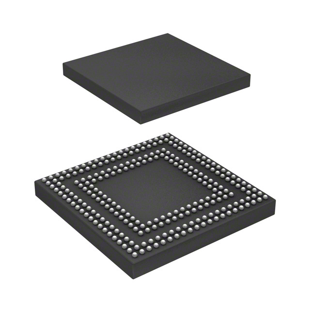
- Part No.:
- R7S721000VCBG#AC0
- Manufacturer:
- Renesas
- Category:
- Microprocessors
- Package:
- 256-LFBGA
- Datasheet:
-
 R7S721000VCBG#AC0.pdf
- Description:
- IC MPU RZ/A1H 400MHZ 256LFBGA
- Quantity:
- Payment:

- Shipping:

Inventory:396
Please send an inquiry. Send us your inquiry, and we will respond immediately.
Product details
Overview
R7S721000VCBG#AC0 from Renesas Electronics is a high-performance 32-bit ARM Cortex-A9 microprocessor unit (MPU) in the RZ/A1H Group, featuring 512 MB DDR3L SDRAM interface, dual-channel 24-bit RGB LCD controller, and integrated 2D graphics accelerator. It operates at up to 400 MHz, supports TrustZone security, and targets embedded human-machine interface (HMI) applications requiring rich GUI and real-time responsiveness.
For engineers reviewing the R7S721000VCBG#AC0 datasheet, R7S721000VCBG#AC0 pinout, R7S721000VCBG#AC0 application, or R7S721000VCBG#AC0 equivalent, key selection criteria include DDR3L timing compliance, LCD panel interface voltage levels (1.8 V/3.3 V), TrustZone-enabled secure boot configuration, and peripheral pin multiplexing flexibility for industrial HMI designs.
Technical Context
The R7S721000VCBG#AC0 implements a dual-core ARM Cortex-A9 MPCore with NEON and VFPv4 extensions, coupled with 256 KB L2 cache and on-chip SRAM (128 KB). Its memory subsystem includes AXI bus interconnect supporting concurrent DDR3L, QSPI, and NAND Flash access with hardware ECC.
Peripherals include three CAN FD controllers (ISO 11898-1:2015 compliant), five USB 2.0 ports (two host, two device, one OTG), and a 12-bit ADC with 16 channels - all managed via a multi-layer AHB/APB bridge architecture with configurable interrupt priority and vector table relocation.
Key Specifications
| Parameter | Value and Actual Design Meaning |
|---|---|
| CPU Core | ARM Cortex-A9 dual-core @ 400 MHz; enables deterministic real-time task scheduling with SMP Linux support |
| Memory Interface | 16-bit DDR3L @ 533 MHz; supports 512 MB density with on-die termination and programmable drive strength |
| Graphics Acceleration | 2D accelerator (RZ/A1H GDC) with 1280×800@60 fps RGB output; eliminates CPU load for GUI layer composition |
| Security | ARM TrustZone + on-chip ROM-based secure boot; enforces authenticated firmware loading before main application execution |
| Peripheral Integration | 3× CAN FD, 5× USB 2.0, 12-bit 16-ch ADC, dual 24-bit RGB LCD controllers; reduces external component count for HMI systems |
| Package | 516-pin BGA (VCBG), 15 mm × 15 mm, 0.65 mm pitch; compatible with standard PCB reflow profiles and automated optical inspection |
| Operating Voltage | Core: 0.95–1.1 V; I/O: 1.8 V / 3.3 V selectable per bank; allows mixed-voltage interface to legacy and modern peripherals |
Pinout & Package
Package: 516-pin Fine-Pitch Ball Grid Array (FBGA), 15 mm × 15 mm, 0.65 mm ball pitch, RoHS-compliant, lead-free finish.
| Pin/Terminal | Circuit Role | Design Meaning |
|---|---|---|
| VDDCORE_0–VDDCORE_7 | Core power supply | Eight dedicated 0.95–1.1 V inputs with decoupling requirements per Renesas Hardware Manual §7.2.1 |
| VDDIO_A–VDDIO_D | I/O bank power | Four independent 1.8 V / 3.3 V selectable supplies; each powers distinct peripheral groups (USB, LCD, CAN, etc.) |
| CLKIN | External clock input | Accepts 12–48 MHz crystal or CMOS clock; feeds PLL for system clock generation (see §6.6.1) |
| RESET_N | Active-low reset input | Synchronous deassertion required after power stabilization and clock lock; initiates secure boot sequence |
| BOOT[3:0] | Boot mode configuration | Four-pin strap defining boot source (QSPI, SD, NAND, USB); latched at power-on reset (§3.2) |
| DMC_DQ0–DMC_DQ15 | DDR3L data bus | 16-bit bidirectional data lines with DQS/DQSN strobes; require matched trace length and on-die termination calibration |
Key Features
| Feature | Design Value |
|---|---|
| Integrated 2D Graphics Accelerator | Offloads GUI rendering from CPU, enabling smooth 1280×800@60 fps display without frame buffer CPU polling |
| TrustZone-enabled Secure Boot | Verifies cryptographic signature of first-stage bootloader in ROM, preventing unauthorized firmware execution |
| Dual Independent LCD Controllers | Drives primary display and secondary overlay (e.g., status bar) simultaneously with independent timing and color depth control |
| Hardware ECC for NAND Flash | Corrects up to 4-bit errors per 512-byte sector, eliminating need for external ECC controller in mass storage designs |
| Configurable I/O Voltage Banks | Four independent VDDIO domains allow direct interfacing to both 1.8 V sensors and 3.3 V industrial I/O without level shifters |
Applications
| Industrial HMI Panel | Medical Device Display Terminal |
|---|---|
Use Scenario: Touch-enabled operator interface for PLC-controlled manufacturing equipment with real-time alarm visualization. IC Role / Device Role / Timing Role: Main application processor executing Linux-based GUI framework while managing CAN FD communication with field devices. Use Value: Dual LCD controllers drive main process view and auxiliary diagnostics screen concurrently; 2D accelerator ensures <16 ms frame latency under full CPU load. | Use Scenario: Portable patient monitor displaying ECG waveforms, vital signs, and alarm indicators with touch navigation. IC Role / Device Role / Timing Role: Central MPU handling sensor data acquisition (via 12-bit ADC), waveform rendering, and secure data logging to encrypted NAND Flash. Use Value: On-chip TrustZone isolates medical application code from OS services; hardware ECC guarantees integrity of stored clinical records. |
| Smart Building Control Gateway | Automotive Infotainment Prototype |
Use Scenario: Edge gateway aggregating BACnet MS/TP, Modbus RTU, and KNX traffic into cloud-uploaded HVAC analytics. IC Role / Device Role / Timing Role: Protocol translation engine running multiple real-time stacks with deterministic USB host control of Zigbee/Z-Wave dongles. Use Value: Five USB 2.0 ports enable simultaneous connection of legacy serial adapters, wireless modules, and debug interfaces without hub ICs. | Use Scenario: Development platform for IVI head unit evaluating Android Automotive OS with rear-seat entertainment output. IC Role / Device Role / Timing Role: Application processor driving dual-display infotainment UI while managing CAN FD vehicle network diagnostics. Use Value: CAN FD controllers support 5 Mbps data phase for fast ECU reprogramming; DDR3L interface sustains >300 MB/s sustained bandwidth for video decode buffers. |
Equivalent & Alternatives
The following parts are listed as comparable options for similar MPU-based HMI applications.
| Alternative Part | Technical Difference | Application Difference | Selection Advice |
|---|---|---|---|
| R7S721020VCBG#AC0 | Same package and pinout; adds 128 MB on-die DDR2 (no external DRAM required); lower max CPU frequency (300 MHz) | Better for space-constrained designs where external DDR layout is impractical; reduced graphics throughput due to lower clock speed | Select when board area is critical and GUI complexity is moderate (e.g., 800×480 displays) |
| i.MX6ULL | ARM Cortex-A7 single-core @ 900 MHz; no integrated 2D accelerator; different package (14x14mm 289-BGA) | Stronger single-thread performance but lacks hardware-accelerated LCD composition; requires external GPU for rich GUI | Select when Linux real-time latency is prioritized over display bandwidth and secure boot depth |
Compared with R7S721000VCBG#AC0, R7S721020VCBG#AC0 trades CPU speed and external memory flexibility for integration density, while i.MX6ULL offers higher single-core throughput but demands external graphics support and lacks TrustZone-based secure boot enforcement.
Availability
R7S721000VCBG#AC0 is available at Aetrix Electronics and suitable for industrial HMI panels, medical display terminals, smart building gateways, and automotive infotainment prototypes requiring stable component supply across multi-year production cycles.
Supply support for R7S721000VCBG#AC0 includes scheduled delivery planning, volume procurement assistance, BOM continuity management, traceable sourcing, and lifecycle availability coordination for OEM customers, industrial embedded developers, connected-device designers, and electronics production programs.
Manufacturer
Renesas Electronics Corporation is a Japanese semiconductor manufacturer specializing in microcontrollers, MPUs, analog, and power devices for industrial, automotive, and enterprise applications.
The RZ/A series, including R7S721000VCBG#AC0, was designed specifically for high-resolution, secure, real-time human-machine interface applications requiring rich graphics, connectivity, and functional safety-aware boot integrity.
FAQ
What is the maximum DDR3L memory capacity supported by the R7S721000VCBG#AC0?
The R7S721000VCBG#AC0 supports up to 512 MB of external DDR3L SDRAM via its 16-bit bus interface. This capacity is validated per Renesas Hardware Manual Rev.7.00 §5.4 address map and timing specification tables. The R7S721000VCBG#AC0 does not integrate on-die DRAM; all memory must be externally populated with JEDEC-compliant DDR3L components meeting tRC, tRCD, and tRP timing requirements specified in the R7S721000VCBG#AC0 datasheet.
Does the R7S721000VCBG#AC0 include hardware support for secure boot?
Yes, the R7S721000VCBG#AC0 implements a ROM-based secure boot flow leveraging ARM TrustZone technology. During power-on reset, the on-chip ROM verifies the cryptographic signature of the first-stage bootloader using SHA-256 and RSA-2048 before execution. This mechanism is mandatory and cannot be disabled, ensuring that only authenticated firmware runs on the R7S721000VCBG#AC0. Configuration details appear in Section 3.2 and Section 12.4 of the R7S721000VCBG#AC0 Hardware Manual.
Can the R7S721000VCBG#AC0 drive two independent LCD panels simultaneously?
Yes, the R7S721000VCBG#AC0 integrates two independent 24-bit RGB LCD controllers capable of driving separate displays with distinct timing parameters, pixel clocks, and color depths. Each controller supports resolutions up to 1280×800@60 Hz. The dual-LCD capability is implemented in hardware without CPU intervention, and pin assignments for both interfaces are fixed per the R7S721000VCBG#AC0 pin diagram in Section 1.4 of the Hardware Manual.
What peripheral interfaces does the R7S721000VCBG#AC0 provide for industrial fieldbus connectivity?
The R7S721000VCBG#AC0 includes three CAN FD controllers compliant with ISO 11898-1:2015, supporting data rates up to 5 Mbps in the data phase. It also provides five UARTs (with IrDA and LIN support), two I²C buses, and four SPI interfaces - all accessible via multiplexed pins defined in Section 1.5 of the R7S721000VCBG#AC0 Hardware Manual. These interfaces enable direct connection to Modbus RTU gateways, BACnet MSTP transceivers, and PROFIBUS DP slaves via appropriate physical layer ICs.
Is the R7S721000VCBG#AC0 qualified for automotive applications?
No, the R7S721000VCBG#AC0 is designated as a "Standard" quality grade product per Renesas documentation and is intended for industrial, medical, and consumer HMI applications - not automotive safety-critical systems. It lacks AEC-Q100 qualification, extended temperature range (-40°C to +105°C), or ASIL-certified functional safety features. For automotive use, Renesas recommends the R-Car family; the R7S721000VCBG#AC0 should not be deployed in vehicles, traffic control, or any system where failure could endanger life or cause catastrophic property damage.
R7S721000VCBG#AC0 Specifications
- Product attributes
- Attribute value
- Manufacturer:
- Renesas
- Package/Case:
- 256-LFBGA
- Series:
- RZ/A1H
- Packaging:
- Tray
- Product Status:
- Active
- Core Processor:
- ARM® Cortex®-A9
- Number of Cores/Bus Width:
- 1 Core, 32-Bit
- Speed:
- 400MHz
- Co-Processors/DSP:
- Multimedia; NEON™ MPE
- RAM Controllers:
- SDRAM, SRAM
- Graphics Acceleration:
- Yes
- Display & Interface Controllers:
- DVD, VDC
- Ethernet:
- 10/100Mbps (1), 100Mbps (1)
- SATA:
- -
- USB:
- USB 2.0 (2)
- Voltage - I/O:
- 1.2V, 3.3V
- Operating Temperature:
- -40°C ~ 85°C (TA)
- Grade:
- -
- Qualification:
- -
- Security Features:
- -
- Mounting Type:
- Surface Mount
- Supplier Device Package:
- 256-LFBGA (11x11)
- Additional Interfaces:
- CAN, I2C, IEBus, IrDA, LIN, MediaLB, MMC/SD/SDIO, SCI, SCI FIFO, SPDIF, SPI, SSI
R7S721000VCBG#AC0 FAQ
1.How can I place an order for R7S721000VCBG#AC0 through Aetrix?
Please submit a Request for Quotation (RFQ) for R7S721000VCBG#AC0 on Aetrix. Our sales agent will provide a competitive quotation and guide you through the order confirmation once you accept the terms.
2.Are the price and stock information for R7S721000VCBG#AC0 reliable?
The price and inventory of R7S721000VCBG#AC0 are updated periodically and may fluctuate due to market conditions. Stock and pricing data are typically refreshed every 24 hours. Quotation validity for R7S721000VCBG#AC0 is usually 5 days.
3.What payment methods are accepted for R7S721000VCBG#AC0?
We accept Wire Transfer, PayPal, Credit Card, Western Union, MoneyGram, and Escrow for R7S721000VCBG#AC0 transactions.
Note: Certain payment methods may incur a processing fee.
4.How is shipping managed for R7S721000VCBG#AC0?
R7S721000VCBG#AC0 orders can be shipped via leading logistics carriers, including DHL, UPS, FedEx, TNT, or Registered Mail.
Once your R7S721000VCBG#AC0 order is processed, you will receive an email with the shipment details and tracking number.
Note: Tracking information may take up to 24 hours to appear. Express delivery typically takes 3–5 business days.
5.How can I obtain technical support or documentation for R7S721000VCBG#AC0?
For technical support, including R7S721000VCBG#AC0 datasheets, pinout diagrams, or application guidance, please contact our engineering support team. They can provide detailed documentation and assistance for your R7S721000VCBG#AC0 requirements.
6.How does Aetrix verify that R7S721000VCBG#AC0 is sourced from the original manufacturer or authorized distributors?
All R7S721000VCBG#AC0 products on Aetrix are procured from qualified distributors and authorized channels. Our dedicated quality assurance team conducts strict verification, including traceability checks and, if necessary, third-party testing. This ensures that R7S721000VCBG#AC0 meets industry standards.
7.What is the process for return or replacement of R7S721000VCBG#AC0?
All R7S721000VCBG#AC0 units undergo pre-shipment inspection (PSI). If there is an issue with R7S721000VCBG#AC0, returns or replacements are accepted under the following conditions:
1.Quantity discrepancies, incorrect items, or visible external defects (such as breakage or corrosion), acknowledged by Aetrix.
2.The issue is reported within 90 days of delivery.
3.The R7S721000VCBG#AC0 part is unused and in its original packaging.
Return procedure for R7S721000VCBG#AC0:
1.Submit a request within 90 days.
2.Obtain a Return Material Authorization (RMA) from Aetrix.
R7S721000VCBG#AC0 Tags

-
AT91SAM9260B-CU-999
Microchip Technology
-
AT91SAM9G25-CU
Microchip Technology

-
ATSAMA5D27C-CU
Microchip Technology
-
AT91SAM9X35-CU
Microchip Technology
-
AT91SAM9X25-CU
Microchip Technology

-
MCIMX6Y2CVM08AB
NXP Semiconductors
.JPG)
-
AM3352BZCZ100
Texas Instruments
-
AT91SAM9260B-CU
Microchip Technology

-
AT91SAM9260B-QU
Microchip Technology

-
ATSAMA5D31A-CU
Microchip Technology
-
AT91SAM9G20B-CU-999
Microchip Technology
-
MCIMX6Y2CVM05AB
NXP Semiconductors
Tech Hub

TTL and CMOS logic families differ in thresholds, loading, output drive, power and timing. This engineering guide compares 74HC and 74HCT, calculates noise margins and checks 3.3 V/5 V compatibility.

A practical engineering guide to 3.3V and 5V logic compatibility, input thresholds, resistor dividers, translator ICs, MOSFET level shifting, I2C pull-ups, timing limits and power-sequencing risks.

The 74HC595 uses push-pull logic outputs, while the TPIC6B595 uses 50 V open-drain DMOS sinks for higher-power loads. This guide compares timing, current limits, 3.3 V interfacing, load wiring, thermal…

The 74HC595 converts serial data into eight stable parallel outputs. This guide covers pin functions, shift and storage timing, OE and MR behavior, drive-current limits, cascading, voltage compatibilit…

A technical comparison of level-sensitive latches and edge-triggered flip-flops, covering timing windows, setup and hold limits, master–slave operation, time borrowing, race-through, HDL inference and…

A D latch stores one bit while Enable controls when data can pass. This reference covers gate-level operation, truth tables, transparency, setup and hold timing, LE versus OE, common ICs and practical …

An SR latch stores one bit through cross-coupled feedback. This engineering reference covers NOR and NAND implementations, truth tables, forbidden-state recovery, gated operation, switch debouncing, fa…

Latch circuits retain one bit through feedback. This technical reference covers SR and D latches, truth tables, transparency, timing limits, latch-versus-flip-flop behavior, applications and common log…

An engineering guide to LED driver operation, constant-current and constant-voltage outputs, linear and switching topologies, dimming, IC selection, calculations, replacement compatibility, and fault c…

Operational amplifier guide covering op amp basics, feedback, ideal vs real op amps, common configurations, buffer circuits, offset, bias current, gain-bandwidth, slew rate, rail-to-rail limits and sel…


