
 My Inquiry
 My Account


Microchip Technology RE46C109E16F
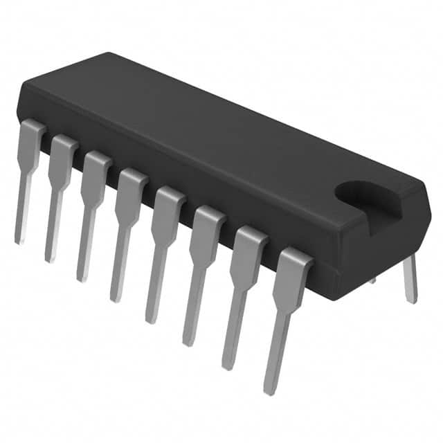
- Part No.:
- RE46C109E16F
- Manufacturer:
- Microchip Technology
- Category:
- Sensor and Detector Interfaces
- Package:
- 16-DIP (0.300", 7.62mm)
- Datasheet:
-
 RE46C109E16F.pdf
- Description:
- IC HORN DRIVER DUAL 16DIP
- Quantity:
- Payment:

- Shipping:

Inventory:4,942
Please send an inquiry. Send us your inquiry, and we will respond immediately.
Product details
Overview
RE46C109E16F from Microchip Technology (via R&E International) is a mixed-signal IC integrating a 3V low-dropout regulator, a 12V switched-capacitor boost converter, and dual high-voltage piezoelectric horn drivers (HORNB/HORNS). It features low-battery detection (LBAT), power-good monitoring (PG), bi-directional interconnect logic (IO1/IO2/IODIR), and operates from 6–12V supply with 6.5µA quiescent current. It is used in battery-powered smoke and CO detectors for audible alarm generation and microcontroller power management.
For engineers reviewing the RE46C109E16F datasheet, RE46C109E16F pinout, RE46C109E16F application, or RE46C109E16F equivalent, key selection considerations include its integrated 12V horn drive capability, 3V LDO output stability under load, LBST-strobed analog low-battery sensing, PG threshold hysteresis, and IO1/IO2 interconnect logic for multi-unit alarm synchronization.
Technical Context
The RE46C109E16F integrates three core subsystems: a bandgap-referenced LDO regulator delivering 3.0V ±150mV at up to 50mA; a charge-pump-based boost converter generating regulated 12V (10.7–12.7V RMS) at up to 16mA output with 85% power efficiency; and dual NMOS horn drivers capable of VPOS-to-VSS swing with <0.5V saturation voltage at 16mA sink/source.
Its interconnect block supports TTL/CMOS-compatible bidirectional communication via IO1/IO2 controlled by IODIR, enabling daisy-chained alarm coordination. Brownout protection disables VREG below 4.5–5.5V VDD, while PG asserts open-drain status when VREG falls below 72–88% of nominal output.
Key Specifications
| Parameter | Value and Actual Design Meaning |
|---|---|
| Supply Voltage Range | 6V to 12V - defines minimum battery voltage for reliable operation and maximum input before absolute max stress |
| VREG Output Voltage | 2.85V to 3.15V - tight 3V regulation for MCU core logic without external feedback |
| VPOS RMS Output | 10.7V to 12.7V - sufficient headroom to drive piezoelectric horns requiring ≥12V peak-to-peak excitation |
| Quiescent Current | ≤6.5µA - enables >5-year battery life in standby mode for smoke/CO detectors |
| Brownout Threshold | 4.5V to 5.5V - ensures clean shutdown before microcontroller reset instability occurs |
| Charge Pump Frequency | 150kHz - determines capacitor sizing (C1=1µF, C2=10µF typical) and EMI profile |
| PG Trip Hysteresis | 72–88% rising/falling - prevents oscillation during marginal VREG transitions |
Pinout & Package
RE46C109E16F is available in a 16-pin SOIC package (E16F suffix denotes SOIC-16 narrow-body, 300 mil width).
| Pin/Terminal | Circuit Role | Design Meaning |
|---|---|---|
| VDD (1) | Main supply input | Accepts 6–12V battery input; powers all internal blocks including LDO, boost, and logic |
| IO1 (2) | Bi-directional interconnect | Configurable as input or output via IODIR; enables alarm synchronization across multiple units |
| IODIR (3) | IO direction control | Determines whether IO1 and IO2 operate as inputs or outputs per truth table |
| IO2 (4) | Bi-directional interconnect | Interfaces with uP/ASIC GPIO; supports TTL/CMOS logic levels |
| LBST (5) | Low-battery strobe enable | Active-high signal that triggers sampling of VDD ratio for LBAT output |
| PG (6) | Power-good status | Open-drain NMOS output indicating VREG is within 72–94% of nominal |
| HRNEN (7) | Horn enable | Activates both boost converter and HORNB/HORNS drivers; disables them in standby |
| VSS (8) | Ground reference | Common return for all analog and digital circuitry; must be low-impedance |
| FEED (9) | Horn driver feedback | Input for external piezo element feedback path; supports resonant frequency tuning |
| HORNS (10) | Horn driver output | Drives one side of piezo element with VPOS-to-VSS swing; ≤0.5V drop at 16mA |
| HORNB (11) | Horn driver output | Drives complementary side of piezo element; matched timing and drive strength to HORNS |
| LBAT (12) | Analog low-battery output | Voltage follower proportional to VDD (0.17–0.23×VDD); used for ADC-based battery monitoring |
| VREG (13) | 3V regulator output | Stable 3V supply for microcontrollers; requires ≥10µF low-ESR output capacitor |
| VCAP− (14) | Boost capacitor negative | Connects to negative terminal of flying capacitor (C1); critical for charge pump operation |
| VCAP+ (15) | Boost capacitor positive | Connects to positive terminal of flying capacitor (C1); forms charge transfer path |
| VPOS (16) | Boost output rail | 12V RMS output supplying HORNB/HORNS; requires external filter capacitor (C4) |
Key Features
| Feature | Design Value |
|---|---|
| Integrated 12V piezo horn drive | Dual NMOS outputs (HORNB/HORNS) deliver full VPOS-to-VSS swing with <0.5V saturation at 16mA, eliminating external H-bridge |
| Ultra-low standby current | 6.5µA max supply current with HRNEN/LBST inactive - extends alkaline battery life beyond 5 years in smoke alarms |
| Programmable interconnect logic | IO1/IO2 bidirectional pins controlled by IODIR enable synchronized multi-unit alarm triggering without external logic |
| Self-contained low-battery detection | LBAT provides analog voltage (0.17–0.23×VDD) with LBST strobe control - eliminates need for external resistor divider or ADC reference |
| Robust power supervision | PG output with 72–88% hysteresis and brownout disable at 4.5–5.5V VDD ensures deterministic system reset behavior |
Applications
| Smoke Detector Alarm System | CO Detector Audio Alert |
|---|---|
Use Scenario: Battery-powered residential smoke detector requiring loud audible alarm and long-term standby. IC Role / Device Role / Timing Role: RE46C109E16F provides 3V power to MCU, generates 12V for piezo horn drive, and signals low battery via LBAT. Use Value: Single-chip integration reduces BOM count by 4–6 discrete components (boost IC, LDO, comparator, driver transistors) and cuts PCB area by >30%. |
Use Scenario: Portable carbon monoxide detector needing reliable audio warning under varying battery conditions. IC Role / Device Role / Timing Role: RE46C109E16F regulates MCU supply, drives piezo horn at full amplitude even at 6V battery, and enables synchronized multi-unit alerts via IO1/IO2. Use Value: Charge-pump efficiency >85% at 6.5V input ensures consistent horn volume across battery discharge curve without DC-DC inductor losses. |
| Personal Security Panic Button | Handheld Instrument Audible Feedback |
Use Scenario: Keychain panic device with momentary button activation and immediate high-volume alert. IC Role / Device Role / Timing Role: RE46C109E16F remains in ultra-low-power sleep until HRNEN is asserted, then instantly enables VPOS and horn drivers. Use Value: 500µs PG delay and sub-100µs horn enable response ensure audible output begins within 1ms of button press. |
Use Scenario: Field-service handheld multimeter requiring tactile audio confirmation of measurement completion. IC Role / Device Role / Timing Role: RE46C109E16F supplies stable 3V to MCU and generates short-duration piezo tone using FEED feedback for precise frequency control. Use Value: FEED pin allows closed-loop tuning of horn resonance, enabling consistent 2.8–4.0kHz tone generation regardless of temperature or component tolerance. |
Equivalent & Alternatives
The following parts are listed as comparable options for similar piezoelectric horn driver and low-voltage regulation applications.
| Alternative Part | Technical Difference | Application Difference | Selection Advice |
|---|---|---|---|
| RE46C110E16F | Same pinout and function but includes internal 3.3V regulator instead of 3.0V; VREG tolerance ±2.5% vs ±50mV | Targeted at systems requiring 3.3V MCU rails; not suitable where 3.0V precision is required for analog sensors | Select RE46C110E16F only if host MCU operates at 3.3V and tighter VREG accuracy is unnecessary |
| TPS61042DRVR | Standalone 28V boost converter (no LDO, no horn drivers, no LBAT/PG); 2.5MHz switching, 0.5A output | Requires external LDO, driver transistors, and battery monitor; higher board cost and layout complexity | Choose TPS61042DRVR only when higher output current (>16mA) or wider input range (1.8–6V) is mandatory |
Compared with RE46C110E16F, the RE46C109E16F offers tighter 3.0V regulation essential for analog sensor biasing, while versus TPS61042DRVR it delivers full system integration-reducing design time by ~3 weeks and eliminating 11 external components in typical smoke detector BOMs.
Availability
RE46C109E16F is available at Aetrix Electronics and suitable for smoke detectors, CO detectors, and personal security products requiring stable component supply, long-life battery operation, and integrated piezoelectric drive capability.
Supply support for RE46C109E16F includes scheduled delivery planning, volume procurement assistance, BOM continuity management, traceable sourcing, and lifecycle availability coordination for OEM customers, industrial embedded developers, connected-device designers, and electronics production programs.
Manufacturer
R&E International, acquired by Microchip Technology in 2006, specializes in highly integrated analog and mixed-signal ICs for safety-critical and battery-powered consumer applications.
The RE46C109E16F belongs to Microchip's legacy R&E alarm interface product line, designed specifically for UL-listed smoke and CO detection systems requiring certified low-power operation and piezo-driven audible alerts.
FAQ
What is the maximum continuous output current capability of the RE46C109E16F horn drivers?
The RE46C109E16F HORNB and HORNS outputs each support up to 16mA continuous sink/source current with ≤0.5V saturation voltage. The absolute maximum continuous operating current for either horn output or VPOS is 50mA, but sustained operation above 16mA degrades efficiency and thermal performance. For reliable piezo actuation, design to the 16mA typical specification rather than the 50mA absolute maximum limit. The RE46C109E16F datasheet specifies Vvpos = 10.7–12.7V RMS at Iout = –16mA.
How does the LBAT pin on the RE46C109E16F provide low-battery indication?
The LBAT pin on the RE46C109E16F outputs an analog voltage proportional to VDD (0.17–0.23 × VDD) only when the LBST pin is driven high. This strobed operation minimizes quiescent current during standby. The output is a buffered voltage follower, so it can directly interface with an MCU's ADC without external scaling. In the RE46C109E16F, LBAT is not continuously active - it requires explicit LBST assertion to sample and hold the battery ratio, making it ideal for periodic battery checks in smoke detectors.
Can the RE46C109E16F drive a piezoelectric horn without external components?
Yes - the RE46C109E16F integrates all necessary circuitry to drive a standard two-terminal piezoelectric horn: dual NMOS drivers (HORNB/HORNS), regulated 12V boost rail (VPOS), feedback input (FEED), and required charge-pump capacitors (VCAP+/VCAP−). Only three external components are mandatory: 10µF VREG output capacitor, 1µF flying capacitor (C1), and 10µF VPOS filter capacitor (C2). No external transistors, diodes, or inductors are needed, making the RE46C109E16F a true single-chip horn solution.
What is the purpose of the FEED pin on the RE46C109E16F?
The FEED pin on the RE46C109E16F serves as the feedback input for the piezoelectric horn driver, enabling closed-loop resonance tracking. When connected to the horn's mechanical resonance node, FEED allows the internal driver circuit to synchronize switching frequency with the horn's natural acoustic resonance - maximizing sound pressure level (SPL) and minimizing current draw. This feature is unique to the RE46C109E16F among integrated horn drivers and is documented in DS22168A-page 7 application notes.
Is the RE46C109E16F RoHS compliant and what packaging options are available?
Yes, the RE46C109E16F is available in RoHS-compliant, lead-free packaging per Microchip's DS22168A specification. The "E16F" suffix explicitly denotes the 16-pin SOIC narrow-body (300 mil) package with Pb-free finish. Standard packaging is also offered, but all new shipments since 2010 comply with RoHS Directive 2011/65/EU. The RE46C109E16F is not offered in DIP; that option was discontinued and applies only to legacy RE46C109 variants without the "E16F" suffix.
RE46C109E16F Specifications
- Product attributes
- Attribute value
- Manufacturer:
- Microchip Technology
- Package/Case:
- 16-DIP (0.300", 7.62mm)
- Series:
- -
- Packaging:
- Tube
- Product Status:
- Active
- Programmable:
- Not Verified
- Type:
- Horn Driver
- Input Type:
- Logic
- Output Type:
- Logic
- Current - Supply:
- 350 µA
- Operating Temperature:
- -40°C ~ 85°C
- Grade:
- -
- Qualification:
- -
- Mounting Type:
- Through Hole
- Supplier Device Package:
- 16-PDIP
RE46C109E16F FAQ
1.How can I place an order for RE46C109E16F through Aetrix?
Please submit a Request for Quotation (RFQ) for RE46C109E16F on Aetrix. Our sales agent will provide a competitive quotation and guide you through the order confirmation once you accept the terms.
2.Are the price and stock information for RE46C109E16F reliable?
The price and inventory of RE46C109E16F are updated periodically and may fluctuate due to market conditions. Stock and pricing data are typically refreshed every 24 hours. Quotation validity for RE46C109E16F is usually 5 days.
3.What payment methods are accepted for RE46C109E16F?
We accept Wire Transfer, PayPal, Credit Card, Western Union, MoneyGram, and Escrow for RE46C109E16F transactions.
Note: Certain payment methods may incur a processing fee.
4.How is shipping managed for RE46C109E16F?
RE46C109E16F orders can be shipped via leading logistics carriers, including DHL, UPS, FedEx, TNT, or Registered Mail.
Once your RE46C109E16F order is processed, you will receive an email with the shipment details and tracking number.
Note: Tracking information may take up to 24 hours to appear. Express delivery typically takes 3–5 business days.
5.How can I obtain technical support or documentation for RE46C109E16F?
For technical support, including RE46C109E16F datasheets, pinout diagrams, or application guidance, please contact our engineering support team. They can provide detailed documentation and assistance for your RE46C109E16F requirements.
6.How does Aetrix verify that RE46C109E16F is sourced from the original manufacturer or authorized distributors?
All RE46C109E16F products on Aetrix are procured from qualified distributors and authorized channels. Our dedicated quality assurance team conducts strict verification, including traceability checks and, if necessary, third-party testing. This ensures that RE46C109E16F meets industry standards.
7.What is the process for return or replacement of RE46C109E16F?
All RE46C109E16F units undergo pre-shipment inspection (PSI). If there is an issue with RE46C109E16F, returns or replacements are accepted under the following conditions:
1.Quantity discrepancies, incorrect items, or visible external defects (such as breakage or corrosion), acknowledged by Aetrix.
2.The issue is reported within 90 days of delivery.
3.The RE46C109E16F part is unused and in its original packaging.
Return procedure for RE46C109E16F:
1.Submit a request within 90 days.
2.Obtain a Return Material Authorization (RMA) from Aetrix.
RE46C109E16F Tags

-
RE46C100S8TF
Microchip Technology

-
XTR111AIDRCR
Texas Instruments

-
XTR111AIDGQR
Texas Instruments

-
XTR117AIDGKR
Texas Instruments
-
XTR111AIDGQT
Texas Instruments

-
XTR115UA/2K5
Texas Instruments

-
MAX14626ETT+T
Analog Devices Inc./Maxim Integrated
-
XTR116UA/2K5
Texas Instruments
-
XTR115U/2K5
Texas Instruments
-
XTR116U/2K5
Texas Instruments

-
PGA308AIDGSR
Texas Instruments

-
XTR300AIRGWR
Texas Instruments
Tech Hub

TTL and CMOS logic families differ in thresholds, loading, output drive, power and timing. This engineering guide compares 74HC and 74HCT, calculates noise margins and checks 3.3 V/5 V compatibility.

A practical engineering guide to 3.3V and 5V logic compatibility, input thresholds, resistor dividers, translator ICs, MOSFET level shifting, I2C pull-ups, timing limits and power-sequencing risks.

The 74HC595 uses push-pull logic outputs, while the TPIC6B595 uses 50 V open-drain DMOS sinks for higher-power loads. This guide compares timing, current limits, 3.3 V interfacing, load wiring, thermal…

The 74HC595 converts serial data into eight stable parallel outputs. This guide covers pin functions, shift and storage timing, OE and MR behavior, drive-current limits, cascading, voltage compatibilit…

A technical comparison of level-sensitive latches and edge-triggered flip-flops, covering timing windows, setup and hold limits, master–slave operation, time borrowing, race-through, HDL inference and…

A D latch stores one bit while Enable controls when data can pass. This reference covers gate-level operation, truth tables, transparency, setup and hold timing, LE versus OE, common ICs and practical …

An SR latch stores one bit through cross-coupled feedback. This engineering reference covers NOR and NAND implementations, truth tables, forbidden-state recovery, gated operation, switch debouncing, fa…

Latch circuits retain one bit through feedback. This technical reference covers SR and D latches, truth tables, transparency, timing limits, latch-versus-flip-flop behavior, applications and common log…

An engineering guide to LED driver operation, constant-current and constant-voltage outputs, linear and switching topologies, dimming, IC selection, calculations, replacement compatibility, and fault c…

Operational amplifier guide covering op amp basics, feedback, ideal vs real op amps, common configurations, buffer circuits, offset, bias current, gain-bandwidth, slew rate, rail-to-rail limits and sel…


