
 My Inquiry
 My Account


Microchip Technology RE46C145SW16F
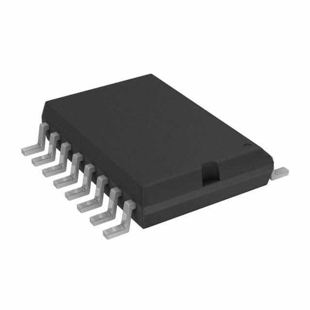
- Part No.:
- RE46C145SW16F
- Manufacturer:
- Microchip Technology
- Category:
- Sensor and Detector Interfaces
- Package:
- 16-SOIC (0.295", 7.50mm Width)
- Datasheet:
-
 RE46C145SW16F.pdf
- Description:
- IC SMOKE DETECTOR CMOS 16-SOIC
- Quantity:
- Payment:

- Shipping:

Inventory:2,123
Please send an inquiry. Send us your inquiry, and we will respond immediately.
Product details
Overview
RE46C145SW16F from Microchip Technology is a CMOS photoelectric smoke detector ASIC with integrated gain-selectable photo amplifier, strobed 100 µs IR detection every 10 seconds (4 µA standby current), UL217/UL268 recognition, temporal horn pattern per NFPA 72, and interconnect capability for up to 40 detectors in residential fire alarm systems.
For engineers reviewing the RE46C145SW16F datasheet, RE46C145SW16F pinout, RE46C145SW16F application, or RE46C145SW16F equivalent, this page delivers verified functional architecture, real-world timing behavior (e.g., 10.5 ms oscillator period, 43 s battery/chamber test interval), UL-compliant alarm sequencing, and precise SOIC-16W package mapping - all confirmed from Microchip DS22181C.
Technical Context
The RE46C145SW16F implements a dual-gain photo amplifier (C1/C2 capacitor-selectable), internal VDD–3.5V reference comparator, and strobe-controlled 100 µs IRED pulsing synchronized to a 10 ms oscillator period set by R9/R12/C5. It executes three consecutive smoke detections before triggering local alarm with horn temporal pattern (500 ms on / 500 ms off).
Its bidirectional IO pin supports interconnect via constant-current drive (local alarm) and 670 ms digital filtering (remote alarm input), while diagnostic mode repurposes VSEN as photoamp output and IO as gain selector - all operating within –25°C to +75°C with 15 V absolute max rating.
Key Specifications
| Parameter | Value and Actual Design Meaning |
|---|---|
| Supply Voltage | 6–12 V - Operates across alkaline/carbon battery discharge curves without external regulation. |
| Standby Current | 4 µA at 9 V - Achieved via 10 s sleep cycles with 100 µs active detection windows. |
| Oscillator Period | 10.5 ms nominal - Sets baseline smoke sampling rate; production-tested parameter. |
| Horn Temporal Pattern | 500 ms on / 500 ms off - Complies with NFPA 72 emergency evacuation signal requirements. |
| Interconnect Support | Up to 40 units - Bidirectional IO pin enables daisy-chained alarm propagation with built-in 670 ms noise filtering. |
| UL Recognition | File S24036, UL217 & UL268 - Certified for use in listed photoelectric smoke detectors. |
| Timer Mode Duration | 10 minutes - Reduces sensitivity via external VSEN reference during temporary high-dust conditions. |
Pinout & Package
RE46C145SW16F is supplied in a 16-lead wide SOIC package (7.50 mm body width, JEDEC MS-013AC), with thermal resistance θJA = 80°C/W.
| Pin/Terminal | Circuit Role | Design Meaning |
|---|---|---|
| 1 (C1) | High-gain capacitor input | Sets photoamp gain for push-to-test and chamber integrity checks (A = 1 + C1/10 pF). |
| 2 (C2) | Normal-gain capacitor input | Sets standby smoke sensitivity (A = 1 + C2/10 pF); gain increases ~10% in alarm for hysteresis. |
| 3 (DETECT) | Photo diode cathode input | Zero-bias interface to external photodiode; referenced to STROBE (VDD–5 V) during sampling. |
| 4 (STROBE) | Strobed negative supply | Regulated VDD–5 V output active only during 100 µs detection window to minimize power. |
| 5 (VDD) | Positive supply input | Accepts 6–12 V; powers all circuitry and hosts low-battery detection (6.9–7.5 V threshold). |
| 6 (IRED) | Infrared emitter driver | Pulsed pre-driver for NPN transistor base; 100–200 µs pulse width set by ROSC/COSC resistor. |
| 7 (IO) | Bidirectional interconnect | Drives high during local alarm; accepts remote alarm signals with 670 ms digital filter. |
| 8 (HB) | Horn brass (inverted) output | Connects to metal electrode of piezoelectric transducer; complements HS for differential drive. |
| 9 (HS) | Horn silver (non-inverted) output | Connects to ceramic electrode; forms full bridge with HB to maximize acoustic output. |
| 10 (FEED) | Horn feedback input | Connects to transducer feedback electrode via current-limiting resistor; disables if tied to VDD/VSS. |
| 11 (LED) | Open-drain LED driver | Drives visible indicator: 10 ms pulse every 43 s (standby), 500 ms period (alarm), or 10 s (timer mode). |
| 12 (COSC) | Oscillator capacitor input | With parallel resistor, sets clock low time (~10 ms period); can be driven externally in diagnostic mode. |
| 13 (ROSC) | Oscillator resistor drive | Resistor to COSC sets clock high time and IRED pulse width; critical for timing accuracy. |
| 14 (VSS) | Negative supply ground | System return path; all analog references and comparators referenced to this node. |
| 15 (VSEN) | Hush/timer sensitivity input | In timer mode, replaces internal VDD–3.5 V reference with external voltage to reduce sensitivity for 10 min. |
| 16 (TEST) | Mode control input | Internal pull-down; high-to-low transition enters timer mode; negative pulse enables diagnostic calibration. |
Key Features
| Feature | Design Value |
|---|---|
| UL217/UL268 Recognition | Validated for certified photoelectric smoke detectors - eliminates need for end-product re-certification. |
| 10-Minute Timer Mode | External VSEN reference allows field-adjustable sensitivity reduction during construction/dusting without hardware change. |
| Temporal Horn Pattern | Pre-programmed 500 ms on/off sequence meets NFPA 72 audible signal requirements for life safety systems. |
| Interconnect Scalability | IO pin supports daisy-chaining up to 40 units with automatic alarm propagation and noise-immune 670 ms filtering. |
| Low-Battery & Chamber Self-Test | Automated 43 s interval checks with distinct chirp patterns - no manual test switch required for compliance. |
Applications
| Residential Smoke Alarms | Commercial Fire Panels |
|---|---|
|
Use Scenario: Standalone ceiling-mounted alarm with battery backup and LED status indicator. IC Role / Device Role / Timing Role: Primary smoke sensing ASIC performing strobed IR detection, alarm decision logic, and temporal horn drive. Use Value: 4 µA standby current extends 9 V alkaline battery life beyond 10 years; UL recognition accelerates listing. |
Use Scenario: Multi-unit addressable fire alarm system with centralized monitoring and zone reporting. IC Role / Device Role / Timing Role: Local sensor node providing interconnect signaling, chamber self-test, and remote alarm synchronization. Use Value: Bidirectional IO pin enables reliable daisy-chain communication without external transceivers or protocol stacks. |
| Temporary Construction Alarms | Hotel/Motel Life Safety Systems |
|
Use Scenario: Deployable smoke detector during building renovation where dust triggers false alarms. IC Role / Device Role / Timing Role: Timer mode controller using VSEN to lower sensitivity for exactly 10 minutes post-button press. Use Value: Eliminates nuisance alarms without disabling protection - no firmware update or hardware modification needed. |
Use Scenario: Networked guest room alarms with synchronized evacuation signaling and battery health reporting. IC Role / Device Role / Timing Role: Integrated low-battery chirp generator (10 ms every 43 s) and chamber integrity verifier. Use Value: Automatic 43 s self-tests ensure continuous compliance with NFPA 72 maintenance requirements. |
Equivalent & Alternatives
The following parts are listed as comparable options for similar photoelectric smoke detector ASIC applications.
| Alternative Part | Technical Difference | Application Difference | Selection Advice |
|---|---|---|---|
| RE46C144SW16F | Lacks timer mode and VSEN pin; no external sensitivity adjustment capability. | Not suitable for environments requiring temporary desensitization (e.g., construction sites). | Select RE46C145SW16F when field-adjustable sensitivity or UL-recognized timer functionality is required. |
| ALLEGRO A5366L | Pin-compatible but lacks UL recognition; requires separate certification for end equipment. | Higher BOM cost due to added external components for battery monitoring and interconnect logic. | Choose RE46C145SW16F for drop-in UL-compliant replacement with integrated diagnostics and lower system-level validation burden. |
Compared with RE46C144SW16F, RE46C145SW16F adds VSEN-based timer mode for temporary sensitivity reduction; versus ALLEGRO A5366L, it provides factory UL recognition and integrated interconnect logic - reducing certification risk and component count.
Availability
RE46C145SW16F is available at Aetrix Electronics and suitable for residential smoke alarms, commercial fire panels, temporary construction safety systems, and hotel/motel life safety deployments requiring stable component supply, long-lifecycle support, and UL-compliant design assurance.
Supply support for RE46C145SW16F includes scheduled delivery planning, volume procurement assistance, BOM continuity management, traceable sourcing, and lifecycle availability coordination for OEM customers, industrial embedded developers, connected-device designers, and electronics production programs.
Manufacturer
Microchip Technology is a U.S.-based semiconductor company specializing in microcontrollers, analog devices, and security ICs, with ISO/TS 16949-certified manufacturing and global technical support infrastructure.
The RE46C145SW16F belongs to Microchip's dedicated smoke detector ASIC product line, engineered specifically for UL217/UL268-compliant photoelectric fire detection systems with minimal external components and robust self-test capabilities.
FAQ
What is the function of the VSEN pin on the RE46C145SW16F?
The VSEN pin on the RE46C145SW16F serves as the hush/timer sensitivity input. During the 10-minute timer mode, it replaces the internal VDD–3.5 V smoke comparator reference with an externally applied voltage, enabling field-adjustable sensitivity reduction. If left unconnected or tied to VSS, timer mode is disabled. This pin is not used in normal standby or alarm operation.
How does the RE46C145SW16F achieve its 4 µA standby current?
The RE46C145SW16F achieves 4 µA standby current by powering down analog circuitry between 10-second intervals, activating detection only for 100 µs per cycle using the STROBE (VDD–5 V) and IRED outputs. The internal oscillator runs at 10.5 ms, and smoke sampling occurs once every 10 seconds - minimizing average current while maintaining responsiveness. This behavior is confirmed in DS22181C, page 3, IDD1 specification.
Is the RE46C145SW16F pin-compatible with the Allegro A5366?
Yes, the RE46C145SW16F is explicitly stated in its datasheet (DS22181C, page 1) as "Compatible with Allegro A5366". Pin functions, timing behavior, and interconnect logic match closely, though RE46C145SW16F adds UL recognition, timer mode, and enhanced self-test features not present in the A5366. No PCB layout changes are required for direct substitution.
What happens during the chamber test performed every 43 seconds on the RE46C145SW16F?
Every 43 seconds, the RE46C145SW16F performs a chamber integrity test by switching to high-gain mode (using C1 capacitor) and measuring background reflections in the smoke chamber. Two consecutive failures trigger a 10 ms horn chirp every 43 seconds - distinct from low-battery chirps and suppressed during local/remote alarms. This test validates optical path cleanliness without user intervention.
Does the RE46C145SW16F support both PDIP and SOIC packages, and what does 'SW' signify?
Yes, the RE46C145SW16F uses the 'SW' suffix per Microchip's Product Identification System (DS22181C, page 23), denoting the Small Plastic Outline – Wide (7.50 mm body) 16-lead SOIC package. Other variants include 'E' for PDIP and 'S' for narrow SOIC. All share identical electrical functionality and pinout; only thermal resistance (θJA = 80°C/W for SW) and mechanical dimensions differ.
RE46C145SW16F Specifications
- Product attributes
- Attribute value
- Manufacturer:
- Microchip Technology
- Package/Case:
- 16-SOIC (0.295", 7.50mm Width)
- Series:
- -
- Packaging:
- Tube
- Product Status:
- Active
- Programmable:
- Not Verified
- Type:
- Smoke Detector
- Input Type:
- Photoelectric
- Output Type:
- Voltage
- Current - Supply:
- 4 µA
- Operating Temperature:
- -25°C ~ 75°C
- Grade:
- -
- Qualification:
- -
- Mounting Type:
- Surface Mount
- Supplier Device Package:
- 16-SOIC
RE46C145SW16F FAQ
1.How can I place an order for RE46C145SW16F through Aetrix?
Please submit a Request for Quotation (RFQ) for RE46C145SW16F on Aetrix. Our sales agent will provide a competitive quotation and guide you through the order confirmation once you accept the terms.
2.Are the price and stock information for RE46C145SW16F reliable?
The price and inventory of RE46C145SW16F are updated periodically and may fluctuate due to market conditions. Stock and pricing data are typically refreshed every 24 hours. Quotation validity for RE46C145SW16F is usually 5 days.
3.What payment methods are accepted for RE46C145SW16F?
We accept Wire Transfer, PayPal, Credit Card, Western Union, MoneyGram, and Escrow for RE46C145SW16F transactions.
Note: Certain payment methods may incur a processing fee.
4.How is shipping managed for RE46C145SW16F?
RE46C145SW16F orders can be shipped via leading logistics carriers, including DHL, UPS, FedEx, TNT, or Registered Mail.
Once your RE46C145SW16F order is processed, you will receive an email with the shipment details and tracking number.
Note: Tracking information may take up to 24 hours to appear. Express delivery typically takes 3–5 business days.
5.How can I obtain technical support or documentation for RE46C145SW16F?
For technical support, including RE46C145SW16F datasheets, pinout diagrams, or application guidance, please contact our engineering support team. They can provide detailed documentation and assistance for your RE46C145SW16F requirements.
6.How does Aetrix verify that RE46C145SW16F is sourced from the original manufacturer or authorized distributors?
All RE46C145SW16F products on Aetrix are procured from qualified distributors and authorized channels. Our dedicated quality assurance team conducts strict verification, including traceability checks and, if necessary, third-party testing. This ensures that RE46C145SW16F meets industry standards.
7.What is the process for return or replacement of RE46C145SW16F?
All RE46C145SW16F units undergo pre-shipment inspection (PSI). If there is an issue with RE46C145SW16F, returns or replacements are accepted under the following conditions:
1.Quantity discrepancies, incorrect items, or visible external defects (such as breakage or corrosion), acknowledged by Aetrix.
2.The issue is reported within 90 days of delivery.
3.The RE46C145SW16F part is unused and in its original packaging.
Return procedure for RE46C145SW16F:
1.Submit a request within 90 days.
2.Obtain a Return Material Authorization (RMA) from Aetrix.
RE46C145SW16F Tags

-
RE46C100S8TF
Microchip Technology

-
XTR111AIDRCR
Texas Instruments

-
XTR111AIDGQR
Texas Instruments

-
XTR117AIDGKR
Texas Instruments
-
XTR111AIDGQT
Texas Instruments

-
XTR115UA/2K5
Texas Instruments

-
MAX14626ETT+T
Analog Devices Inc./Maxim Integrated
-
XTR116UA/2K5
Texas Instruments
-
XTR115U/2K5
Texas Instruments
-
XTR116U/2K5
Texas Instruments

-
PGA308AIDGSR
Texas Instruments

-
XTR300AIRGWR
Texas Instruments
Tech Hub

TTL and CMOS logic families differ in thresholds, loading, output drive, power and timing. This engineering guide compares 74HC and 74HCT, calculates noise margins and checks 3.3 V/5 V compatibility.

A practical engineering guide to 3.3V and 5V logic compatibility, input thresholds, resistor dividers, translator ICs, MOSFET level shifting, I2C pull-ups, timing limits and power-sequencing risks.

The 74HC595 uses push-pull logic outputs, while the TPIC6B595 uses 50 V open-drain DMOS sinks for higher-power loads. This guide compares timing, current limits, 3.3 V interfacing, load wiring, thermal…

The 74HC595 converts serial data into eight stable parallel outputs. This guide covers pin functions, shift and storage timing, OE and MR behavior, drive-current limits, cascading, voltage compatibilit…

A technical comparison of level-sensitive latches and edge-triggered flip-flops, covering timing windows, setup and hold limits, master–slave operation, time borrowing, race-through, HDL inference and…

A D latch stores one bit while Enable controls when data can pass. This reference covers gate-level operation, truth tables, transparency, setup and hold timing, LE versus OE, common ICs and practical …

An SR latch stores one bit through cross-coupled feedback. This engineering reference covers NOR and NAND implementations, truth tables, forbidden-state recovery, gated operation, switch debouncing, fa…

Latch circuits retain one bit through feedback. This technical reference covers SR and D latches, truth tables, transparency, timing limits, latch-versus-flip-flop behavior, applications and common log…

An engineering guide to LED driver operation, constant-current and constant-voltage outputs, linear and switching topologies, dimming, IC selection, calculations, replacement compatibility, and fault c…

Operational amplifier guide covering op amp basics, feedback, ideal vs real op amps, common configurations, buffer circuits, offset, bias current, gain-bandwidth, slew rate, rail-to-rail limits and sel…


