
 My Inquiry
 My Account


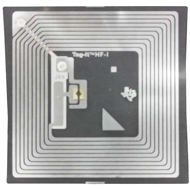
Texas Instruments RI-I11-114A-S1
- Part No.:
- RI-I11-114A-S1
- Manufacturer:
- Texas Instruments
- Category:
- RFID Transponders, Tags
- Package:
- Datasheet:
-
 RI-I11-114A-S1.pdf
- Description:
- RFID TAG R/W 13.56MHZ INLAY
- Quantity:
- Payment:

- Shipping:

Inventory:1,369
Please send an inquiry. Send us your inquiry, and we will respond immediately.
Product details
Overview
RI-I11-114A-S1 from Texas Instruments is a passive 13.56 MHz HF RFID transponder inlay compliant with ISO/IEC 15693-2,-3 and ISO/IEC 18000-3 standards, featuring a 45 mm × 45 mm aluminum antenna on PET foil, factory-programmed 64-bit UID, and 256-bit user EEPROM organized in eight 32-bit lockable blocks - deployed in paper-based smart labels for asset tagging and electronic ticketing.
For engineers reviewing the RI-I11-114A-S1 datasheet, RI-I11-114A-S1 pinout, RI-I11-114A-S1 application, or RI-I11-114A-S1 equivalent, this inlay's frequency offset (13.86 MHz ± 200 kHz) is specifically tuned for optimal resonance after integration into paper substrates, and its activation field strength (98 dBµA/m typical read, 101 dBµA/m typical write) defines minimum reader power requirements in label-conversion environments.
Technical Context
The RI-I11-114A-S1 implements full-duplex ASK/FSK subcarrier modulation per ISO/IEC 15693, supporting both 1-out-of-4 and 1-out-of-256 downlink coding and high/low data rate uplink modes. Its laser-trimmed aluminum capacitor compensates process and material tolerances to maintain target resonance post-lamination.
It features collision-resistant anticollision via UID-based inventory commands, password-protected WriteSingleBlockPwd (0xA5), and factory-locked UID blocks (0x00–0x01). Memory is nonvolatile EEPROM rated for 100,000 programming cycles and >10 years data retention at 55°C.
Key Specifications
| Parameter | Value and Actual Design Meaning |
|---|---|
| Operating Frequency | 13.86 MHz ± 200 kHz - frequency offset pre-tuned for minimal detuning after lamination into paper substrates. |
| Antenna Dimensions | 45 mm × 45 mm - square aluminum antenna geometry optimized for balanced read range and orientation tolerance in label formats. |
| Read Field Strength | 98 dBµA/m typical - minimum magnetic field intensity required at 25°C for reliable block reads in paper-integrated labels. |
| User Memory | 256 bits (8 × 32-bit blocks) - field-programmable EEPROM with individual block locking and password-protected rewrites. |
| UID Length | 64 bits - factory-programmed, permanently locked identifier enabling unique device addressing and anticollision inventory. |
| Operating Temp | –25°C to +70°C - validated thermal range for deployment in indoor logistics, access control, and transit ticketing environments. |
| Foil Pitch | 48 mm +0.1 mm / –0.4 mm - precise tape spacing enabling high-speed die-cutting and label conversion on standard rotary equipment. |
Pinout & Package
RI-I11-114A-S1 is a passive RFID inlay with no electrical pins or terminals. It consists of a flip-chip mounted IC electrically coupled to an integrated aluminum antenna etched on both sides of a 0.085 mm PET substrate. The device has no leads, pads, or solderable interfaces - connection is exclusively via electromagnetic coupling to a 13.56 MHz reader antenna.
Key Features
| Feature | Design Value |
|---|---|
| Laser-trimmed capacitor | Individually tuned resonance ensures consistent 13.86 MHz operation across all units after paper lamination. |
| Factory-locked UID | 64-bit read-only identifier prevents cloning and enables deterministic one-to-one communication in dense tag fields. |
| Per-block memory lock | Each 32-bit user block can be independently write-locked; locked blocks require password (0xA5) for modification. |
| ISO/IEC 15693 compliance | Supports mandatory inventory, read/write/lock commands and optional AFI - interoperable with global HF readers. |
| Paper-optimized frequency offset | 13.86 MHz center frequency compensates dielectric loading from cellulose fibers, maintaining read range post-conversion. |
Applications
| Asset Tracking Labels | Electronic Transit Tickets |
|---|---|
Use Scenario: Paper-based labels affixed to IT equipment, medical devices, or library books for automated check-in/out and lifecycle logging. IC Role / Device Role / Timing Role: Passive transponder providing secure, battery-free identification and field-updatable status metadata. Use Value: 256-bit user memory stores asset ID, calibration date, and maintenance history; UID enables unambiguous database linking without manual entry. |
Use Scenario: Disposable paper tickets used in bus, metro, or event access systems requiring tamper-resistant encoding and fast batch reads. IC Role / Device Role / Timing Role: ISO-compliant HF transponder serving as secure credential storage and usage counter. Use Value: Password-protected write capability allows real-time balance updates; 100,000-cycle EEPROM supports multi-ride reuse over 3+ years. |
| Anti-Counterfeit Product Tags | Building Access Badges |
Use Scenario: Embedded in branded packaging (e.g., pharmaceutical blister packs or luxury goods boxes) to verify authenticity at point-of-sale. IC Role / Device Role / Timing Role: Cryptographically agnostic but UID-secured element enabling brand-authorized verification workflows. Use Value: Factory-locked UID prevents duplication; per-block locking protects origin timestamp and batch code from unauthorized overwrite. |
Use Scenario: Laminated PVC or composite badges issued to employees for door access, with encoded department, clearance level, and expiry. IC Role / Device Role / Timing Role: Contactless identity token interfacing with ISO 15693–compliant access controllers. Use Value: 45 mm × 45 mm antenna delivers robust read performance at 5–10 cm distance even when badge is in wallet or pocket. |
Equivalent & Alternatives
The following parts are listed as comparable options for similar HF RFID inlay applications.
| Alternative Part | Technical Difference | Application Difference | Selection Advice |
|---|---|---|---|
| RI-I11-114B-S1 | Resonance frequency 14.4 MHz ± 200 kHz - tuned for PVC lamination, not paper. | Optimized for rigid plastic badges or laminated ID cards, not flexible paper labels. | Select RI-I11-114B-S1 only when integrating into PVC or polycarbonate substrates where dielectric constant differs significantly from paper. |
| RI-I02-114A-S1 | Rectangular 45 mm × 76 mm antenna; same 13.86 MHz offset and paper optimization. | Provides longer read range in linear orientation; suited for pallet tags or elongated product packaging. | Choose RI-I02-114A-S1 when label format requires directional read performance or larger surface area for adhesive bonding. |
Compared with RI-I11-114A-S1, RI-I11-114B-S1 shifts resonance for PVC compatibility - risking 3–5 dB read loss in paper - while RI-I02-114A-S1 retains identical frequency tuning but extends antenna length to improve linear-range sensitivity at the cost of square-format footprint compatibility.
Availability
RI-I11-114A-S1 is available at Aetrix Electronics and suitable for asset tagging, electronic ticketing, anti-counterfeit labeling, and building access badge applications requiring stable component supply, reel-based automation compatibility, and paper-integration reliability.
Supply support for RI-I11-114A-S1 includes scheduled delivery planning, volume procurement assistance, BOM continuity management, traceable sourcing, and lifecycle availability coordination for OEM customers, industrial embedded developers, connected-device designers, and electronics production programs.
Manufacturer
Texas Instruments is a global semiconductor company specializing in analog, embedded processing, and wireless connectivity solutions, with decades of leadership in RFID and contactless identification technologies.
The Tag-it™ HF-I Pro family - including RI-I11-114A-S1 - was designed for high-volume, low-cost smart label manufacturing, emphasizing mechanical robustness, lamination-tolerant resonance, and ISO-standard interoperability in industrial and consumer identification systems.
FAQ
What is the purpose of the frequency offset in RI-I11-114A-S1?
The 13.86 MHz ± 200 kHz resonance frequency of RI-I11-114A-S1 is intentionally offset to compensate for detuning caused by the dielectric properties of paper substrates during lamination. This ensures the inlay maintains optimal coupling efficiency and read range after final label assembly - a critical design feature confirmed in TI's SCBU009B specification tables for RI-I11-114A-S1.
Does RI-I11-114A-S1 have electrical pins or solderable terminals?
No, RI-I11-114A-S1 is a fully passive RFID inlay with no pins, pads, or electrical contacts. It operates solely through electromagnetic induction between its integrated aluminum antenna and a 13.56 MHz reader coil. The device contains no interface circuitry beyond the flip-chip mounted IC and resonant LC structure defined in Figure 1-2 of the TI reference guide.
Can RI-I11-114A-S1 be used in PVC-based badges?
RI-I11-114A-S1 is explicitly tuned for paper integration and will exhibit suboptimal resonance - typically reduced read range and higher required field strength - when laminated into PVC. For PVC applications, TI specifies RI-I11-114B-S1 (14.4 MHz ± 200 kHz) as the correct variant, as documented in Table 2-2 of SCBU009B.
How is memory protected on RI-I11-114A-S1?
RI-I11-114A-S1 provides two-tier memory protection: (1) individual 32-bit blocks can be permanently locked via Lock_Block (0x22), preventing further writes; (2) locked blocks may be rewritten only using the password-protected WriteSingleBlockPwd command (0xA5), which requires knowledge of the stored 6-byte password. Both mechanisms are implemented in silicon and verified in TI's memory organization diagram (Figure 1-3).
What is the maximum number of RI-I11-114A-S1 inlays a reader can identify simultaneously?
RI-I11-114A-S1 supports ISO/IEC 15693 anticollision protocols enabling up to 50 tags per second identification throughput - dependent on reader hardware, antenna design, and field uniformity. This capability is enabled by its factory-programmed 64-bit UID and standardized inventory command set (0x01), as specified in Table 1-1 and Section 1.4 of the TI reference guide.
RI-I11-114A-S1 Specifications
- Product attributes
- Attribute value
- Manufacturer:
- Texas Instruments
- Series:
- Tag-it™ HF-I Pro Square Inlays
- Packaging:
- Tape & Reel (TR)
- Product Status:
- Obsolete
- Style:
- Inlay
- Technology:
- Passive
- Frequency:
- 13.56MHz
- Memory Type:
- Read/Write
- Writable Memory:
- 2kb (User)
- Standards:
- ISO 15693, ISO 18000-3
- Operating Temperature:
- -25°C ~ 70°C
- Size / Dimension:
- 1.772" L x 1.772" W (45.00mm x 45.00mm)
RI-I11-114A-S1 FAQ
1.How can I place an order for RI-I11-114A-S1 through Aetrix?
Please submit a Request for Quotation (RFQ) for RI-I11-114A-S1 on Aetrix. Our sales agent will provide a competitive quotation and guide you through the order confirmation once you accept the terms.
2.Are the price and stock information for RI-I11-114A-S1 reliable?
The price and inventory of RI-I11-114A-S1 are updated periodically and may fluctuate due to market conditions. Stock and pricing data are typically refreshed every 24 hours. Quotation validity for RI-I11-114A-S1 is usually 5 days.
3.What payment methods are accepted for RI-I11-114A-S1?
We accept Wire Transfer, PayPal, Credit Card, Western Union, MoneyGram, and Escrow for RI-I11-114A-S1 transactions.
Note: Certain payment methods may incur a processing fee.
4.How is shipping managed for RI-I11-114A-S1?
RI-I11-114A-S1 orders can be shipped via leading logistics carriers, including DHL, UPS, FedEx, TNT, or Registered Mail.
Once your RI-I11-114A-S1 order is processed, you will receive an email with the shipment details and tracking number.
Note: Tracking information may take up to 24 hours to appear. Express delivery typically takes 3–5 business days.
5.How can I obtain technical support or documentation for RI-I11-114A-S1?
For technical support, including RI-I11-114A-S1 datasheets, pinout diagrams, or application guidance, please contact our engineering support team. They can provide detailed documentation and assistance for your RI-I11-114A-S1 requirements.
6.How does Aetrix verify that RI-I11-114A-S1 is sourced from the original manufacturer or authorized distributors?
All RI-I11-114A-S1 products on Aetrix are procured from qualified distributors and authorized channels. Our dedicated quality assurance team conducts strict verification, including traceability checks and, if necessary, third-party testing. This ensures that RI-I11-114A-S1 meets industry standards.
7.What is the process for return or replacement of RI-I11-114A-S1?
All RI-I11-114A-S1 units undergo pre-shipment inspection (PSI). If there is an issue with RI-I11-114A-S1, returns or replacements are accepted under the following conditions:
1.Quantity discrepancies, incorrect items, or visible external defects (such as breakage or corrosion), acknowledged by Aetrix.
2.The issue is reported within 90 days of delivery.
3.The RI-I11-114A-S1 part is unused and in its original packaging.
Return procedure for RI-I11-114A-S1:
1.Submit a request within 90 days.
2.Obtain a Return Material Authorization (RMA) from Aetrix.
RI-I11-114A-S1 Tags
-
SL3S1013FTB0,115
NXP Semiconductors
-
NTP53321G0JHKZ
NXP Semiconductors
-
HTSH4801ETK,118
NXP Semiconductors
-
NTA53321G0FHKZ
NXP Semiconductors
-
RF-HDT-DVBE-N2
Texas Instruments
-
RF-HDT-DVBB-N2
Texas Instruments
-
HT2DC20S20/F/RSP
NXP Semiconductors
-
TRPGR30ATGA
Texas Instruments
-
TRPGR30ATGC
Texas Instruments
-
RI-TRP-DR2B-40
Texas Instruments
-
V680-D1KP52MT
Omron Automation and Safety
-
HTMS8001FTB/AF,115
NXP USA Inc.
Tech Hub

A practical engineering guide to 3.3V and 5V logic compatibility, input thresholds, resistor dividers, translator ICs, MOSFET level shifting, I2C pull-ups, timing limits and power-sequencing risks.

The 74HC595 uses push-pull logic outputs, while the TPIC6B595 uses 50 V open-drain DMOS sinks for higher-power loads. This guide compares timing, current limits, 3.3 V interfacing, load wiring, thermal…

The 74HC595 converts serial data into eight stable parallel outputs. This guide covers pin functions, shift and storage timing, OE and MR behavior, drive-current limits, cascading, voltage compatibilit…

A technical comparison of level-sensitive latches and edge-triggered flip-flops, covering timing windows, setup and hold limits, master–slave operation, time borrowing, race-through, HDL inference and…

A D latch stores one bit while Enable controls when data can pass. This reference covers gate-level operation, truth tables, transparency, setup and hold timing, LE versus OE, common ICs and practical …

An SR latch stores one bit through cross-coupled feedback. This engineering reference covers NOR and NAND implementations, truth tables, forbidden-state recovery, gated operation, switch debouncing, fa…

Latch circuits retain one bit through feedback. This technical reference covers SR and D latches, truth tables, transparency, timing limits, latch-versus-flip-flop behavior, applications and common log…

An engineering guide to LED driver operation, constant-current and constant-voltage outputs, linear and switching topologies, dimming, IC selection, calculations, replacement compatibility, and fault c…

Operational amplifier guide covering op amp basics, feedback, ideal vs real op amps, common configurations, buffer circuits, offset, bias current, gain-bandwidth, slew rate, rail-to-rail limits and sel…

Jumper cables guide covering safe connection order, red and black clamp placement, final ground connection, cable gauge, length, clamp quality, copper vs CCA cables, jump starter comparison and battery…


