
 My Inquiry
 My Account


Texas Instruments RI-I16-114A-S1
- Part No.:
- RI-I16-114A-S1
- Manufacturer:
- Texas Instruments
- Category:
- RFID Transponders, Tags
- Package:
- Datasheet:
-
 RI-I16-114A-S1.pdf
- Description:
- RFID TAG R/W 13.56MHZ INLAY
- Quantity:
- Payment:

- Shipping:

Inventory:2,132
Please send an inquiry. Send us your inquiry, and we will respond immediately.
Product details
Overview
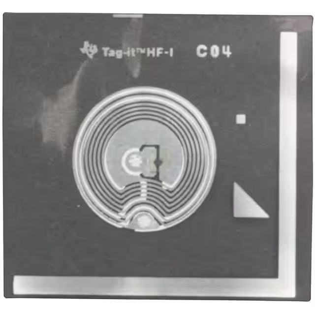
RI-I16-114A-S1 from Texas Instruments is a passive 13.56 MHz HF RFID transponder inlay in 24.2 mm circular format, compliant with ISO/IEC 15693-2,-3 and ISO/IEC 18000-3 standards, featuring 256-bit user EEPROM memory, factory-programmed 64-bit UID, and resonance frequency of 13.70 MHz ±400 kHz optimized for integration into paper or PVC laminates used in smart labels.
For engineers reviewing the RI-I16-114A-S1 datasheet, RI-I16-114A-S1 antenna size, RI-I16-114A-S1 activation field strength, or RI-I16-114A-S1 equivalent, this inlay supports high-speed inventory of up to 50 tags/sec, password-protected write operations, individual block locking, and AFI support - critical for asset tagging, anti-counterfeit labeling, and electronic ticketing applications requiring reliable read/write performance after lamination.
Technical Context
The RI-I16-114A-S1 implements full-duplex communication using ASK or FSK subcarrier modulation on the uplink and ASK (10–30% or 100%) with pulse-position coding on the downlink. It supports all ISO/IEC 15693 mandatory commands including Inventory, Read_Single_Block, Write_Single_Block, and Lock_Block, plus TI-custom Kill and WriteSingleBlockPwd commands.
Its resonant circuit integrates a flip-chip mounted microchip with an aluminum antenna and laser-trimmed capacitor formed by dual-layer aluminum on PET foil, enabling per-device frequency tuning to compensate detuning from substrate integration - confirmed by its specified 13.70 MHz ±400 kHz resonance at 25°C after paper/PVC lamination.
Key Specifications
| Parameter | Value and Actual Design Meaning |
|---|---|
| Operating Frequency | 13.56 MHz carrier; enables interoperability with ISO/IEC 15693 readers and global HF RFID infrastructure. |
| Resonance Frequency | 13.70 MHz ±400 kHz at 25°C - tuned offset ensures stable operation post-lamination into paper or PVC substrates. |
| Antenna Size | ∅24.2 mm +0.1/−0.2 mm - compact circular form factor ideal for small-area labeling and CD/disk-based applications. |
| Read Activation Field | Typical 113 dBµA/m - defines minimum reader field strength required for reliable read operation after lamination. |
| Write Activation Field | Typical 116 dBµA/m - higher than read threshold, confirming robust write margin under real-world lamination-induced detuning. |
| User Memory | 256 bits (8 × 32-bit blocks) - supports discrete data segmentation with per-block lock capability for secure, granular data protection. |
| Data Retention | >10 years at 55°C - ensures long-term validity of encoded information in industrial or archival environments. |
Pinout & Package
This is a passive RFID transponder inlay with no electrical pins or terminals. It consists of a silicon chip flip-chip bonded to an aluminum antenna pattern embedded in a PET substrate, forming a monolithic resonant structure. No external connections are made - coupling occurs wirelessly via magnetic induction at 13.56 MHz.
Key Features
| Feature | Design Value |
|---|---|
| Factory-Programmed UID | 64-bit unique identifier permanently locked at manufacture - enables collision-free multi-tag inventory and unforgeable device identity. |
| Password-Protected Write | WriteSingleBlockPwd command requires valid password before modifying locked blocks - prevents unauthorized data alteration in deployed labels. |
| Per-Block Locking | Each of eight 32-bit memory blocks can be individually locked - allows mixed security policies (e.g., public ID + protected payload) within one inlay. |
| Laser-Trimmed Capacitor | Dual-layer aluminum capacitor tuned per unit - compensates manufacturing and material tolerances to maintain target resonance after lamination. |
| AFI Support | Application Family Identifier field implemented - enables reader-level filtering of tag types in mixed-environment deployments. |
Applications
| Asset Tagging | Anti-Counterfeit Labels |
|---|---|
Use Scenario: Tracking high-value tools, medical devices, or IT equipment across maintenance cycles and facility transfers. IC Role / Device Role / Timing Role: Passive transponder inlay providing tamper-resistant, battery-free identification and service history logging. Use Value: Enables rapid, simultaneous scan of dozens of tagged assets using ISO-compliant readers - reducing manual audit time by >90% versus barcode systems. | Use Scenario: Embedding authenticatable identifiers into pharmaceutical packaging, luxury goods, or branded electronics. IC Role / Device Role / Timing Role: Secure data carrier storing encrypted batch codes, production dates, and cryptographic signatures in locked memory blocks. Use Value: Prevents cloning via factory-locked UID and password-gated write access - verified during point-of-sale or customs inspection. |
| Electronic Ticketing | CD/Disk Media Identification |
Use Scenario: Issuing reusable event passes, transit cards, or venue access credentials printed on paper or plastic substrates. IC Role / Device Role / Timing Role: Read/write transponder inlay supporting dynamic balance updates, entry validation, and session logging. Use Value: Supports >100,000 programming cycles - ensuring multi-season durability without memory wear-out in high-turnover ticketing systems. | Use Scenario: Integrating identification into audio CDs, software distribution disks, or archival media for content authentication and license binding. IC Role / Device Role / Timing Role: Circular 24.2 mm inlay conforming to CD geometry - placed near hub or outer edge for optimal reader coupling. Use Value: ∅24.2 mm size matches standard CD inner diameter constraints - enabling seamless integration without mechanical redesign of disk manufacturing tooling. |
Equivalent & Alternatives
The following parts are listed as comparable options for similar passive HF RFID inlay applications.
| Alternative Part | Technical Difference | Application Difference | Selection Advice |
|---|---|---|---|
| RI-I17-114A-S1 | Larger 32.5 mm circular antenna; resonance 13.80 MHz ±400 kHz; higher read sensitivity (110 dBµA/m typical). | Better suited for applications requiring longer read range or integration into thicker media where larger antenna area improves coupling. | Select RI-I17-114A-S1 when physical space allows and extended read distance is prioritized over compact footprint. |
| RI-I03-114A-S1 | Rectangular 22.5 × 38 mm format; resonance 13.86 MHz ±200 kHz; lower read sensitivity (107 dBµA/m typical) but tighter frequency tolerance. | Optimized for narrow-format labels (e.g., cable ties, wristbands) where circular geometry is impractical. | Choose RI-I03-114A-S1 for linear or constrained-space labeling where rectangular layout aligns with printing or die-cutting processes. |
Compared with RI-I16-114A-S1, RI-I17-114A-S1 offers greater read range due to larger antenna area but requires more label real estate, while RI-I03-114A-S1 provides superior frequency stability in narrow formats but sacrifices some lamination tolerance - making RI-I16-114A-S1 the balanced choice for compact circular applications like disk media or small asset tags.
Availability
RI-I16-114A-S1 is available at Aetrix Electronics and suitable for asset tagging, anti-counterfeit labeling, electronic ticketing, and CD/disk media identification requiring stable component supply across high-volume label converter programs.
Supply support for RI-I16-114A-S1 includes scheduled delivery planning, volume procurement assistance, BOM continuity management, traceable sourcing, and lifecycle availability coordination for OEM customers, industrial embedded developers, connected-device designers, and electronics production programs.
Manufacturer
Texas Instruments is a global semiconductor company specializing in analog, embedded processing, and wireless connectivity solutions, with decades of leadership in RFID technology and industrial-grade RF components.
The Tag-it™ HF-I Pro product line was designed specifically for high-reliability, printable passive HF RFID inlays targeting smart label converters - emphasizing lamination-tolerant resonance tuning, ISO/IEC 15693 compliance, and field-programmable memory security.
FAQ
What is the resonance frequency specification for RI-I16-114A-S1, and why is it offset?
The RI-I16-114A-S1 has a passive resonance frequency of 13.70 MHz ±400 kHz at 25°C, intentionally offset to compensate for detuning that occurs when the inlay is laminated into paper or PVC substrates. This pre-compensation ensures the final assembled label maintains optimal 13.56 MHz operation, maximizing read/write reliability in end-use conditions - a key differentiator confirmed in Table 2-5 of the SCBU009B reference guide.
Does RI-I16-114A-S1 support password-protected writes, and how is it implemented?
Yes, RI-I16-114A-S1 supports password-protected writes via the TI-custom WriteSingleBlockPwd command. This command requires a valid password to modify memory blocks previously locked with the Lock_Block command. The password mechanism is implemented in firmware and validated per ISO/IEC 15693 protocol - enabling secure reprogramming of protected data fields without exposing the entire memory array.
What is the maximum number of tags RI-I16-114A-S1 can support in simultaneous inventory mode?
The RI-I16-114A-S1 supports simultaneous identification of up to 50 tags per second, as stated in Table 2-1 of the SCBU009B specification. This performance depends on reader/antenna capabilities and environmental conditions but is enabled by the inlay's ISO/IEC 15693-compliant anticollision protocol and fast frame synchronization - allowing high-throughput scanning in logistics or retail inventory scenarios.
Can RI-I16-114A-S1 be integrated into PVC-based smart cards, and what design consideration applies?
Yes, RI-I16-114A-S1 is explicitly qualified for integration into both paper and PVC laminates, as noted in Table 2-5 footnote (1). Its 13.70 MHz ±400 kHz resonance offset is engineered to counteract the dielectric loading effect of PVC, ensuring stable 13.56 MHz operation post-lamination - eliminating the need for custom tuning during card manufacturing.
What memory organization does RI-I16-114A-S1 use, and how is data protection enforced?
RI-I16-114A-S1 uses 256-bit user memory organized in eight 32-bit blocks, each individually lockable via the Lock_Block command. Once locked, a block can only be rewritten using the password-protected WriteSingleBlockPwd command. This architecture - detailed in Figure 1-3 and Section 1.5 - enables flexible security partitioning, such as locking UID-related metadata while leaving payload fields open for field updates.
RI-I16-114A-S1 Specifications
- Product attributes
- Attribute value
- Manufacturer:
- Texas Instruments
- Series:
- Tag-it™ HF-I Pro Circular Inlays
- Packaging:
- Tape & Reel (TR)
- Product Status:
- Obsolete
- Style:
- Inlay
- Technology:
- Passive
- Frequency:
- 13.56MHz
- Memory Type:
- Read/Write
- Writable Memory:
- 2kb (User)
- Standards:
- ISO 15693, ISO 18000-3
- Operating Temperature:
- -25°C ~ 70°C
- Size / Dimension:
- 24.20mm Dia x 0.34mm
RI-I16-114A-S1 FAQ
1.How can I place an order for RI-I16-114A-S1 through Aetrix?
Please submit a Request for Quotation (RFQ) for RI-I16-114A-S1 on Aetrix. Our sales agent will provide a competitive quotation and guide you through the order confirmation once you accept the terms.
2.Are the price and stock information for RI-I16-114A-S1 reliable?
The price and inventory of RI-I16-114A-S1 are updated periodically and may fluctuate due to market conditions. Stock and pricing data are typically refreshed every 24 hours. Quotation validity for RI-I16-114A-S1 is usually 5 days.
3.What payment methods are accepted for RI-I16-114A-S1?
We accept Wire Transfer, PayPal, Credit Card, Western Union, MoneyGram, and Escrow for RI-I16-114A-S1 transactions.
Note: Certain payment methods may incur a processing fee.
4.How is shipping managed for RI-I16-114A-S1?
RI-I16-114A-S1 orders can be shipped via leading logistics carriers, including DHL, UPS, FedEx, TNT, or Registered Mail.
Once your RI-I16-114A-S1 order is processed, you will receive an email with the shipment details and tracking number.
Note: Tracking information may take up to 24 hours to appear. Express delivery typically takes 3–5 business days.
5.How can I obtain technical support or documentation for RI-I16-114A-S1?
For technical support, including RI-I16-114A-S1 datasheets, pinout diagrams, or application guidance, please contact our engineering support team. They can provide detailed documentation and assistance for your RI-I16-114A-S1 requirements.
6.How does Aetrix verify that RI-I16-114A-S1 is sourced from the original manufacturer or authorized distributors?
All RI-I16-114A-S1 products on Aetrix are procured from qualified distributors and authorized channels. Our dedicated quality assurance team conducts strict verification, including traceability checks and, if necessary, third-party testing. This ensures that RI-I16-114A-S1 meets industry standards.
7.What is the process for return or replacement of RI-I16-114A-S1?
All RI-I16-114A-S1 units undergo pre-shipment inspection (PSI). If there is an issue with RI-I16-114A-S1, returns or replacements are accepted under the following conditions:
1.Quantity discrepancies, incorrect items, or visible external defects (such as breakage or corrosion), acknowledged by Aetrix.
2.The issue is reported within 90 days of delivery.
3.The RI-I16-114A-S1 part is unused and in its original packaging.
Return procedure for RI-I16-114A-S1:
1.Submit a request within 90 days.
2.Obtain a Return Material Authorization (RMA) from Aetrix.
RI-I16-114A-S1 Tags
-
SL3S1013FTB0,115
NXP Semiconductors
-
NTP53321G0JHKZ
NXP Semiconductors
-
HTSH4801ETK,118
NXP Semiconductors
-
NTA53321G0FHKZ
NXP Semiconductors
-
RF-HDT-DVBE-N2
Texas Instruments
-
RF-HDT-DVBB-N2
Texas Instruments
-
HT2DC20S20/F/RSP
NXP Semiconductors
-
TRPGR30ATGA
Texas Instruments
-
TRPGR30ATGC
Texas Instruments
-
RI-TRP-DR2B-40
Texas Instruments
-
V680-D1KP52MT
Omron Automation and Safety
-
HTMS8001FTB/AF,115
NXP USA Inc.
Tech Hub

A practical engineering guide to 3.3V and 5V logic compatibility, input thresholds, resistor dividers, translator ICs, MOSFET level shifting, I2C pull-ups, timing limits and power-sequencing risks.

The 74HC595 uses push-pull logic outputs, while the TPIC6B595 uses 50 V open-drain DMOS sinks for higher-power loads. This guide compares timing, current limits, 3.3 V interfacing, load wiring, thermal…

The 74HC595 converts serial data into eight stable parallel outputs. This guide covers pin functions, shift and storage timing, OE and MR behavior, drive-current limits, cascading, voltage compatibilit…

A technical comparison of level-sensitive latches and edge-triggered flip-flops, covering timing windows, setup and hold limits, master–slave operation, time borrowing, race-through, HDL inference and…

A D latch stores one bit while Enable controls when data can pass. This reference covers gate-level operation, truth tables, transparency, setup and hold timing, LE versus OE, common ICs and practical …

An SR latch stores one bit through cross-coupled feedback. This engineering reference covers NOR and NAND implementations, truth tables, forbidden-state recovery, gated operation, switch debouncing, fa…

Latch circuits retain one bit through feedback. This technical reference covers SR and D latches, truth tables, transparency, timing limits, latch-versus-flip-flop behavior, applications and common log…

An engineering guide to LED driver operation, constant-current and constant-voltage outputs, linear and switching topologies, dimming, IC selection, calculations, replacement compatibility, and fault c…

Operational amplifier guide covering op amp basics, feedback, ideal vs real op amps, common configurations, buffer circuits, offset, bias current, gain-bandwidth, slew rate, rail-to-rail limits and sel…

Jumper cables guide covering safe connection order, red and black clamp placement, final ground connection, cable gauge, length, clamp quality, copper vs CCA cables, jump starter comparison and battery…


