
 My Inquiry
 My Account


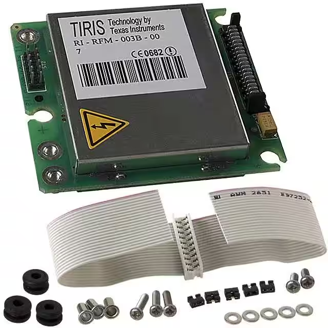
Texas Instruments RI-RFM-003B-00
- Part No.:
- RI-RFM-003B-00
- Manufacturer:
- Texas Instruments
- Category:
- RFID Reader Modules
- Package:
- Module
- Datasheet:
-
 RI-RFM-003B-00.pdf
- Description:
- RFID READER R/W 134.2KHZ MODULE
- Quantity:
- Payment:

- Shipping:

Inventory:2,481
Please send an inquiry. Send us your inquiry, and we will respond immediately.
Product details
Overview
RI-RFM-003B from Texas Instruments is a TIRIS™ Mini-Radio Frequency Module designed for 134.2 kHz RFID reader systems. It functions as the RF interface between TIRIS transponders and host control units, performing transponder energization (50 ms charge pulse), FSK demodulation of returned ID data, and write capability. It delivers NRZ data (RXDT), synchronized clock (RXCK), and inverted RSSI output (RXSS-) for portable or stationary identification systems with medium read/write range.
For engineers reviewing the RI-RFM-003B datasheet, RI-RFM-003B pinout, RI-RFM-003B application, or RI-RFM-003B equivalent, key selection considerations include its dual-supply architecture (VSP up to 6 V / VSRL at 5 V), antenna tuning via binary-weighted capacitors (C_AT1–C_AT6), transmitter control via active-low TXCT-, and compatibility with HCMOS logic levels.
Technical Context
The RI-RFM-003B implements a crystal-controlled 134.2 kHz transmitter (f_TX = 134.1–134.3 kHz) with push-pull power stage driving antenna terminal A1, and a selective receiver tuned to 128.2 kHz center frequency (±11 kHz bandwidth) for FSK demodulation. Transmitter activation is edge-triggered by low-going TXCT-, while TPC adjusts duty cycle to regulate RF field strength.
Its antenna circuit integrates six binary-weighted tuning capacitors (C_AT1–C_AT6, 1–32 normalized steps) accessible via ST2 connector, enabling precise resonance compensation for external coils like RI-ANT-P02A. The module separates logic (GNDL/VSRL) and power-stage (GNDP/VSP) grounds with internal decoupling (R_GND = 9–33 Ω), supporting stable operation under high-current transmit pulses.
Key Specifications
| Parameter | Value and Actual Design Meaning |
|---|---|
| Operating Frequency | 134.2 kHz transmitter (134.1–134.3 kHz); 128.2 kHz receiver center frequency - enables interoperability with TIRIS transponders requiring precise magnetic coupling at this ISM band. |
| Supply Voltages | VSP = 4.5–6 V (transmitter power stage); VSRL = 4.75–5.25 V (logic/receiver) - supports direct NiCd battery input while maintaining regulated logic supply. |
| Transmit Pulse | 50 ms energizing burst per read cycle; t_off ≥ 310 ms between writes - defines minimum cycle time and thermal limits for continuous operation. |
| Output Signals | RXDT (NRZ data stream), RXCK (bit-center-aligned clock), RXSS- (inverted analog RSSI) - provides fully decoded transponder ID with timing reference and signal-strength feedback for synchronization. |
| Antenna Tuning Range | C_AT1–C_AT6 total capacitance: 0–63 × step value (e.g., C_AT1 = 50–64 pF, C_AT6 = 1425–1575 pF) - allows fine-tuning of LC resonance to compensate for coil tolerance and environmental drift. |
| Logic Compatibility | HCMOS-level I/O (VIH = 4–5 V, VIL = 0–1 V; VOH = 2–4 V, VOL = 0.5 V) - ensures direct interfacing with standard microcontrollers without level-shifting. |
| Thermal Limits | Operating temperature: 0–50°C free-air; storage: –25–85°C - constrains deployment in uncontrolled industrial or outdoor enclosures without forced cooling. |
Pinout & Package
RI-RFM-003B is housed in a compact PCB-mounted module measuring 60.2 × 55.1 × 10.4 mm (body height), with metal shielding on both sides and captive nut antenna terminals (A1, A2, A3). Connectors ST1 (20-pin) and ST2 (12-pin) provide access to all signals and tuning elements.
| Pin/Terminal | Circuit Role | Design Meaning |
|---|---|---|
| ST1 Pin 1–4 | VSP | + supply for transmitter power stage; four parallel pins reduce impedance and thermal stress during 1.2 A peak current. |
| ST1 Pin 5–8 | GNDP | – return for transmitter power stage; isolated from logic ground to prevent noise coupling into sensitive receiver paths. |
| ST1 Pin 9 | GNDL | – return for logic and receiver; must be externally tied to GNDP via low-inductance path to maintain <0.5 V potential difference. |
| ST1 Pin 10 | VSRL | +5 V regulated supply for receiver and logic circuits; decoupled internally to reject ripple from VSP switching. |
| ST1 Pin 14 | TXCT- | Active-low transmitter enable; internal 22 kΩ pull-up ensures safe default OFF state during MCU reset or initialization. |
| ST1 Pin 15 | TPC | Transmitter power control; low level reduces RF field intensity by modulating duty cycle - used for range adjustment or EMI compliance. |
| ST1 Pin 16 | RXCK | Receiver clock output; transitions mid-bit for reliable NRZ data sampling; 1 µs rise/fall time compatible with 5 MHz MCU inputs. |
| ST1 Pin 18 | RXDT | Demodulated NRZ data output; contains transponder ID, protection bits, and framing - requires synchronous capture using RXCK. |
| ST1 Pin 20 | RXSS- | Inverted analog RSSI voltage; decreases with stronger received signal - used for automatic gain control or proximity detection. |
| ST2 Pin 1,3,5,7,9,11 | C_AT6–C_AT1 | Binary-weighted tuning capacitors (32,16,8,4,2,1 steps); shorting any pin to adjacent GNDP selects that capacitance value. |
| A1, A2, A3 | Antenna Terminals | A1 = transmitter output; A2 = damping node; A3 = antenna ground (GNDP) - strict wiring rules prevent damage (e.g., no A1–A3 connection). |
Key Features
| Feature | Design Value |
|---|---|
| Dual-Supply Architecture | Separate VSP/GNDP (high-current) and VSRL/GNDL (low-noise) rails minimize supply coupling and enable battery-powered portables with stable logic operation. |
| Binary Capacitor Tuning | Six ST2-accessible weighted capacitors (C_AT1–C_AT6) provide 64 discrete resonance settings - eliminates need for variable capacitors or iterative soldering during antenna calibration. |
| Integrated Receiver Demodulation | On-chip FSK demodulator outputs clean digital RXDT and synchronized RXCK - removes requirement for external decoder ICs or FPGA-based signal processing. |
| Transmitter Power Control | TPC input adjusts RF field strength via duty-cycle modulation - supports regulatory compliance (e.g., FCC Part 15), multi-antenna systems, and reduced power consumption. |
| HCMOS Logic Compatibility | All digital I/O meet HCMOS voltage thresholds (VIH ≥ 4 V, VIL ≤ 1 V) - allows direct connection to common MCUs (e.g., TI MSP430, STM32) without external buffers or level shifters. |
Applications
| Animal Identification | Access Control |
|---|---|
|
Use Scenario: Implantable glass transponders in livestock or pets are read at point-of-care scanners or handheld readers. IC Role / Device Role / Timing Role: RI-RFM-003B generates the 134.2 kHz magnetic field to energize passive transponders and demodulates their backscattered FSK response within 50 ms + 310 ms cycle. Use Value: Enables reliable read range up to 10 cm with standard stick antennas (e.g., RI-ANT-P02A), meeting ISO 11784/11785 requirements for animal ID. |
Use Scenario: Door-mounted RFID readers authenticate personnel badges or vehicle tags in secure facilities. IC Role / Device Role / Timing Role: RI-RFM-003B interfaces with microcontroller-based access controllers to energize and decode TIRIS transponders, delivering ID data via RXDT/RXCK for real-time validation. Use Value: Provides deterministic 4 Hz read repetition rate and RSSI-based presence detection (via RXSS-) to prevent false triggers from nearby tags. |
| Industrial Asset Tracking | Manufacturing WIP Management |
|
Use Scenario: Metal-enclosed tools or pallets carry TIRIS transponders scanned at docking stations or conveyor checkpoints. IC Role / Device Role / Timing Role: RI-RFM-003B drives custom-tuned loop antennas mounted inside machinery housings, compensating for detuning effects using C_AT1–C_AT6. Use Value: Binary capacitor tuning maintains resonance despite temperature shifts or metallic interference, ensuring >99% read reliability in factory environments. |
Use Scenario: Assembly line workstations verify component IDs on PCBs or subassemblies before soldering or testing. IC Role / Device Role / Timing Role: RI-RFM-003B operates in write mode (t_wrt = 310 ms) to program unique serial numbers into reusable TIRIS transponders attached to fixtures or carriers. Use Value: Integrated write capability eliminates need for separate programming hardware, reducing station footprint and integration complexity. |
Equivalent & Alternatives
The following parts are listed as comparable options for similar RFID reader front-end applications.
| Alternative Part | Technical Difference | Application Difference | Selection Advice |
|---|---|---|---|
| RI-RFM-002B | Same 134.2 kHz architecture but lacks TPC input and RXSS- output; fixed-power transmitter only. | Not suitable for RSSI-based proximity sensing or adaptive field strength control in multi-antenna systems. | Select RI-RFM-002B only when cost sensitivity outweighs need for programmable output power or signal-strength feedback. |
| TRF7960ARHBT | Multi-frequency (125/134/13.56 MHz) NFC/RFID analog front-end with integrated digital controller; requires external MCU firmware. | Supports ISO 14443/15693 but not TIRIS protocol natively; demands significant software development vs. RI-RFM-003B's plug-and-play interface. | Choose TRF7960ARHBT when future-proofing for multiple standards or migrating from legacy TIRIS to modern contactless protocols. |
Compared with RI-RFM-002B, the RI-RFM-003B adds critical flexibility via TPC and RXSS- for adaptive reading; versus TRF7960ARHBT, it delivers immediate TIRIS compliance with zero firmware overhead but lacks multi-standard support.
Availability
RI-RFM-003B is available at Aetrix Electronics and suitable for animal identification systems, access control readers, and industrial asset tracking solutions requiring stable component supply and long-term obsolescence management.
Supply support for RI-RFM-003B includes scheduled delivery planning, volume procurement assistance, BOM continuity management, traceable sourcing, and lifecycle availability coordination for OEM customers, industrial embedded developers, connected-device designers, and electronics production programs.
Manufacturer
Texas Instruments is a global semiconductor company specializing in analog, embedded processing, and connectivity technologies, with decades of leadership in RFID and wireless identification solutions.
The RI-RFM-003B belongs to TI's TIRIS™ Mini-RFM series, engineered specifically for low-cost, high-reliability 134.2 kHz RFID reader designs targeting animal ID, access control, and industrial tagging applications.
FAQ
What is the primary function of the RI-RFM-003B in a TIRIS RFID system?
The RI-RFM-003B serves as the RF front-end interface between TIRIS transponders and host controllers. It generates the 134.2 kHz magnetic field to energize passive transponders, demodulates their FSK-encoded ID data into digital RXDT and synchronized RXCK signals, and supports write operations. Its design enables complete RFID read/write functionality without requiring additional RF signal processing components.
How does the antenna tuning mechanism work on the RI-RFM-003B?
The RI-RFM-003B uses six binary-weighted capacitors (C_AT1–C_AT6) accessible via ST2 connector pins to tune the external antenna's LC resonance. Each capacitor corresponds to a normalized value (1, 2, 4, 8, 16, 32), and shorting a pin to its adjacent GNDP selects that capacitance. This 64-step array compensates for manufacturing tolerances in antenna coils like RI-ANT-P02A, ensuring optimal power transfer and read range.
Why does the RI-RFM-003B use separate power and logic grounds (GNDP and GNDL)?
The RI-RFM-003B separates GNDP (power stage return) and GNDL (logic/receiver return) to prevent high-current transmitter switching noise from corrupting sensitive analog receiver paths. Internal decoupling (R_GND = 9–33 Ω) allows controlled potential difference (<0.5 V), and external connection of GNDP/GNDL near the power source minimizes ground loops - essential for stable FSK demodulation in noisy industrial environments.
What is the role of the TPC signal on the RI-RFM-003B?
The TPC (Transmitter Power Control) input on the RI-RFM-003B modulates the duty cycle of the transmitter power stage to adjust RF field strength. When TPC is low, output power is reduced - enabling compliance with regional EMI regulations, extending battery life in portable readers, and optimizing read range in multi-antenna installations where field overlap must be avoided.
Can the RI-RFM-003B be used with antennas other than the RI-ANT-P02A?
Yes, the RI-RFM-003B supports custom antennas beyond RI-ANT-P02A, provided they are tuned to 134.2 kHz using the C_AT1–C_AT6 array. Mechanical data (e.g., inductance, Q-factor) must match the module's drive capability (1.2 A max VSP current), and antenna terminals must connect strictly to A1 and A2 - never A1–A3 or A2–A3 - to avoid damaging the power stage.
RI-RFM-003B-00 Specifications
- Product attributes
- Attribute value
- Manufacturer:
- Texas Instruments
- Series:
- 2000
- Package/Case:
- Module
- Packaging:
- Bulk
- Product Status:
- Obsolete
- Type:
- Read/Write
- Frequency:
- 134.2kHz
- Interface:
- -
- Standards:
- ISO 11785
- Supplier Device Package:
- -
RI-RFM-003B-00 FAQ
1.How can I place an order for RI-RFM-003B-00 through Aetrix?
Please submit a Request for Quotation (RFQ) for RI-RFM-003B-00 on Aetrix. Our sales agent will provide a competitive quotation and guide you through the order confirmation once you accept the terms.
2.Are the price and stock information for RI-RFM-003B-00 reliable?
The price and inventory of RI-RFM-003B-00 are updated periodically and may fluctuate due to market conditions. Stock and pricing data are typically refreshed every 24 hours. Quotation validity for RI-RFM-003B-00 is usually 5 days.
3.What payment methods are accepted for RI-RFM-003B-00?
We accept Wire Transfer, PayPal, Credit Card, Western Union, MoneyGram, and Escrow for RI-RFM-003B-00 transactions.
Note: Certain payment methods may incur a processing fee.
4.How is shipping managed for RI-RFM-003B-00?
RI-RFM-003B-00 orders can be shipped via leading logistics carriers, including DHL, UPS, FedEx, TNT, or Registered Mail.
Once your RI-RFM-003B-00 order is processed, you will receive an email with the shipment details and tracking number.
Note: Tracking information may take up to 24 hours to appear. Express delivery typically takes 3–5 business days.
5.How can I obtain technical support or documentation for RI-RFM-003B-00?
For technical support, including RI-RFM-003B-00 datasheets, pinout diagrams, or application guidance, please contact our engineering support team. They can provide detailed documentation and assistance for your RI-RFM-003B-00 requirements.
6.How does Aetrix verify that RI-RFM-003B-00 is sourced from the original manufacturer or authorized distributors?
All RI-RFM-003B-00 products on Aetrix are procured from qualified distributors and authorized channels. Our dedicated quality assurance team conducts strict verification, including traceability checks and, if necessary, third-party testing. This ensures that RI-RFM-003B-00 meets industry standards.
7.What is the process for return or replacement of RI-RFM-003B-00?
All RI-RFM-003B-00 units undergo pre-shipment inspection (PSI). If there is an issue with RI-RFM-003B-00, returns or replacements are accepted under the following conditions:
1.Quantity discrepancies, incorrect items, or visible external defects (such as breakage or corrosion), acknowledged by Aetrix.
2.The issue is reported within 90 days of delivery.
3.The RI-RFM-003B-00 part is unused and in its original packaging.
Return procedure for RI-RFM-003B-00:
1.Submit a request within 90 days.
2.Obtain a Return Material Authorization (RMA) from Aetrix.
RI-RFM-003B-00 Tags
-
DLP-RFID2
DLP Design Inc.
-
DLP-RFID1-OG
DLP Design Inc.

-
M7E-PICO
ThingMagic, a JADAK brand
-
DLP-RFID1
DLP Design Inc.
-
RI-STU-MRD2
Texas Instruments
-
M7E-DEKA
ThingMagic, a JADAK brand
-
M7E-PICO-CB
ThingMagic, a JADAK brand
-
ARRUN5-915.000MHZ
Abracon LLC
-
ARRSN5-868.000MHZ
Abracon LLC
-
ARRUN5-868.000MHZ
Abracon LLC
-
RI-SMD-MRD2
Texas Instruments
-
4606.000.01
FEIG Electronic
Tech Hub

A practical engineering guide to 3.3V and 5V logic compatibility, input thresholds, resistor dividers, translator ICs, MOSFET level shifting, I2C pull-ups, timing limits and power-sequencing risks.

The 74HC595 uses push-pull logic outputs, while the TPIC6B595 uses 50 V open-drain DMOS sinks for higher-power loads. This guide compares timing, current limits, 3.3 V interfacing, load wiring, thermal…

The 74HC595 converts serial data into eight stable parallel outputs. This guide covers pin functions, shift and storage timing, OE and MR behavior, drive-current limits, cascading, voltage compatibilit…

A technical comparison of level-sensitive latches and edge-triggered flip-flops, covering timing windows, setup and hold limits, master–slave operation, time borrowing, race-through, HDL inference and…

A D latch stores one bit while Enable controls when data can pass. This reference covers gate-level operation, truth tables, transparency, setup and hold timing, LE versus OE, common ICs and practical …

An SR latch stores one bit through cross-coupled feedback. This engineering reference covers NOR and NAND implementations, truth tables, forbidden-state recovery, gated operation, switch debouncing, fa…

Latch circuits retain one bit through feedback. This technical reference covers SR and D latches, truth tables, transparency, timing limits, latch-versus-flip-flop behavior, applications and common log…

An engineering guide to LED driver operation, constant-current and constant-voltage outputs, linear and switching topologies, dimming, IC selection, calculations, replacement compatibility, and fault c…

Operational amplifier guide covering op amp basics, feedback, ideal vs real op amps, common configurations, buffer circuits, offset, bias current, gain-bandwidth, slew rate, rail-to-rail limits and sel…

Jumper cables guide covering safe connection order, red and black clamp placement, final ground connection, cable gauge, length, clamp quality, copper vs CCA cables, jump starter comparison and battery…


