
 My Inquiry
 My Account


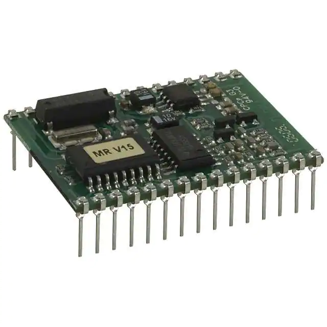
Texas Instruments RI-STU-MRD1-30
- Part No.:
- RI-STU-MRD1-30
- Manufacturer:
- Texas Instruments
- Category:
- RFID Reader Modules
- Package:
- 38.3mm x 29.3mm 13.5mm
- Datasheet:
-
 RI-STU-MRD1-30.pdf
- Description:
- RFID READER R/W 134.2KHZ
- Quantity:
- Payment:

- Shipping:

Inventory:2,490
Please send an inquiry. Send us your inquiry, and we will respond immediately.
Product details
Overview
RI-STU-MRD1-30 from Texas Instruments is a TIRIS™ low-frequency (134.2 kHz) micro-reader module designed for contactless identification systems. It integrates RF excitation, transponder protocol handling, and TTL-level serial communication (9600 baud, 8N1), supporting read-only, read/write, MPT, and SAMPT transponders with 50 ms power burst duration and wired/wireless synchronization.
For engineers reviewing the RI-STU-MRD1-30 datasheet, RI-STU-MRD1-30 pinout, RI-STU-MRD1-30 application, or RI-STU-MRD1-30 equivalent, this module serves as a complete embedded LF RFID reader subsystem-requiring only a 47 µH antenna, dual 5 V supplies (VSL/VSP), and minimal host controller logic for command-driven operation in access control, asset tracking, and industrial ID systems.
Technical Context
The RI-STU-MRD1-30 implements a dedicated ASIC-based RF front-end with integrated power stage and microcontroller, operating at 134.2 kHz using a fixed 47 µH low-Q antenna (Q = 10–20) to eliminate tuning requirements. Its serial interface uses half-duplex TTL-level signaling with XON/XOFF handshake support and strict 41-byte frame limit.
It supports three operational modes: idle (command-waiting), triggered single-read (via RDEN− pulse), and continuous read (via CRDM). Synchronization-wired (SYNC/RDEN−) or wireless (WLSC)-adds ~20 ms cycle overhead and ensures reliable multi-reader coexistence without signal collision in dense deployments.
Key Specifications
| Parameter | Value and Actual Design Meaning |
|---|---|
| Operating Frequency | 134.2 kHz - Fixed carrier frequency optimized for TIRIS™ LF transponders; no tuning required with specified 47 µH antenna. |
| Power Burst Duration | 50 ms - Standard excitation window per read/program cycle; configurable via command field for extended bursts. |
| Serial Interface | TTL-level UART at 9600 baud, 8N1 - Direct connection to microcontroller GPIO; RS232/RS422 requires external driver. |
| Supply Requirements | Dual 5 V inputs: VSL (logic, 4–5.5 V) and VSP (output stage, 4–5.5 V); SMPS prohibited below 200 kHz fundamental frequency. |
| Transponder Support | RO, R/W, MPT, SAMPT - Full native protocol stack per TIRIS™ specification; includes FBCC/DBCC calculation and selective page operations. |
| Read Rate (unsync) | ~10 readouts/sec - Determined by 50 ms burst + internal processing; synchronized mode adds ~20 ms latency per cycle. |
| Antenna Interface | 47 µH, Q = 10–20 - Low-Q design enables robust operation across temperature and mechanical variance; ANTCAP allows inductance adaptation. |
Pinout & Package
RI-STU-MRD1-30 is a 30-pin through-hole plug-in module with dual-row 0.1″ pitch layout. Mechanical dimensions are provided in Figure 3-1 (top/front/side views, mm). The module mounts directly to an adapter board and requires no solder reflow profile-designed for manual insertion and wave soldering.
| Pin/Terminal | Circuit Role | Design Meaning |
|---|---|---|
| 1 (SYNC) | Wired sync output | Open-drain VSL-level signal active during full RF cycle; used to coordinate multiple readers on shared bus. |
| 2 (RDEN−) | Sync/trigger input | Active-high input for wired sync hold-off or 100 µs pulse-triggered single read; high-impedance, requires 27 kΩ pull-down when unused. |
| 4 (RESET−) | Active-low reset | Asynchronous reset; min. 1 ms pulse; internal pull-up allows floating if unused; 28–132 ms recovery before serial commands accepted. |
| 5 (RXD) / 6 (TXD) | Half-duplex UART I/O | TTL-level (0 V / VSL) serial interface; 9600 baud, 8N1; supports XON/XOFF flow control; no hardware handshaking. |
| 16 (ANT1) / 19 (ANT2) | Antenna terminals | Connect 47 µH low-Q coil between ANT1 and ANT2; ANTCAP (pin 17) enables parallel capacitance for inductance scaling. |
| 22 (VSP) / 24 (VSL) | Power inputs | VSP powers RF output stage; VSL powers logic/microcontroller; separate decoupling recommended even with common 5 V source. |
| 26 (CRDM) | Continuous read enable | Active-high input forces charge-only continuous read mode; serial commands retain priority and preempt CRDM state. |
| 27 (WLSC) | Wireless sync control | Active-high enables wireless sync; overridden temporarily by serial command; must be pulled to VSL or GND via 27 kΩ resistor. |
| 29 (OKT) / 30 (STAT) | Status outputs | OKT pulses high (~60 ms) on valid transponder read; STAT goes low during RF transmission-both drive LEDs directly. |
Key Features
| Feature | Design Value |
|---|---|
| Integrated TIRIS™ Protocol Engine | Hardware-accelerated support for RO, R/W, MPT, and SAMPT transponders-including FBCC/DBCC generation and selective page locking. |
| No-Tune Antenna Interface | Optimized for 47 µH, Q = 10–20 coils; eliminates calibration labor and improves production yield across environmental variance. |
| Dual-Supply Architecture | Separate VSL (logic) and VSP (RF output) rails prevent noise coupling; enables clean digital control of high-current RF stage. |
| Multi-Reader Synchronization | Wired (SYNC/RDEN−) and wireless (WLSC) modes ensure deterministic timing in stacked or adjacent reader deployments. |
| Command-Driven Operational Modes | Idle, single-triggered, and continuous read modes-all selectable via pin or serial command; CRDM and RDEN− inputs retain priority over serial. |
Applications
| Access Control System | Industrial Asset Tracking |
|---|---|
|
Use Scenario: Door-mounted reader verifies employee badge ID before granting entry. IC Role / Device Role / Timing Role: Standalone LF RFID reader subsystem handling transponder excitation, demodulation, and protocol decoding. Use Value: 50 ms burst duration and OKT/STAT outputs enable fast visual feedback and deterministic door actuation timing. |
Use Scenario: Forklift-mounted reader logs pallet ID during loading/unloading in warehouse. IC Role / Device Role / Timing Role: Embedded reader module interfacing with vehicle MCU via TTL UART; operates in continuous Line Mode. Use Value: Continuous read with Line Mode ensures every valid ID is reported-no ID dropouts during rapid movement near antenna. |
| Automotive Keyless Entry | Tool Crib Management |
|
Use Scenario: Vehicle-side reader detects proximity of authorized key fob to unlock doors. IC Role / Device Role / Timing Role: Low-power LF exciter with wireless synchronization to avoid interference from nearby vehicles. Use Value: WLSC-enabled wireless sync prevents false triggers when multiple cars park adjacent, maintaining secure proximity detection. |
Use Scenario: Tool cabinet reader validates technician ID and tool return status upon checkout. IC Role / Device Role / Timing Role: Reader module integrated into cabinet controller; uses MPT protocol for encrypted tool data storage. Use Value: Native MPT/SAMPT support enables secure, write-protected tool usage logging without external crypto IC. |
Equivalent & Alternatives
The following parts are listed as comparable options for similar LF RFID reader applications.
| Alternative Part | Technical Difference | Application Difference | Selection Advice |
|---|---|---|---|
| RI-TRP-WM2B | Same TIRIS™ family; surface-mount variant with integrated antenna matching network and 3.3 V logic compatibility. | Designed for space-constrained PCB integration; lacks direct RDEN−/CRDM pin control-relies entirely on serial commands. | Select RI-TRP-WM2B for compact, automated assembly where board real estate is limited and host MCU handles all sequencing. |
| TRF7960ARHBT | TI multi-protocol NFC/LF HF reader IC (13.56 MHz + 125 kHz); programmable analog front-end; requires external MCU and antenna tuning. | Supports ISO14443A/B, FeliCa, and TIRIS™ but demands full firmware development; no built-in transponder protocol engine. | Select TRF7960ARHBT when future multi-frequency support or custom protocol extensions are required-accepting higher BOM and firmware cost. |
Compared with RI-STU-MRD1-30, RI-TRP-WM2B reduces mechanical footprint and simplifies power design but removes direct hardware trigger flexibility; TRF7960ARHBT offers broader frequency coverage and configurability at the expense of added system complexity and development effort.
Availability
RI-STU-MRD1-30 is available at Aetrix Electronics and suitable for access control systems, industrial asset tracking, and automotive keyless entry requiring stable component supply, long-term lifecycle assurance, and legacy TIRIS™ ecosystem compatibility.
Supply support for RI-STU-MRD1-30 includes scheduled delivery planning, volume procurement assistance, BOM continuity management, traceable sourcing, and lifecycle availability coordination for OEM customers, industrial embedded developers, connected-device designers, and electronics production programs.
Manufacturer
Texas Instruments is a global semiconductor company specializing in analog, embedded processing, and connectivity technologies, with leadership in industrial, automotive, and communications markets.
The RI-STU-MRD1-30 belongs to TI's TIRIS™ family of dedicated LF RFID reader modules, engineered for plug-and-play integration into secure identification systems without requiring RF expertise or protocol stack development.
FAQ
What is the primary function of the RI-STU-MRD1-30?
The RI-STU-MRD1-30 is a complete TIRIS™ low-frequency (134.2 kHz) RFID micro-reader module that performs RF excitation, transponder communication, and protocol handling for RO, R/W, MPT, and SAMPT tags. It delivers decoded ID data via TTL UART and provides hardware status signals (OKT/STAT) for direct LED or MCU monitoring-eliminating the need for external RF or protocol firmware development in the host system.
Does the RI-STU-MRD1-30 require antenna tuning?
No, the RI-STU-MRD1-30 is designed for use with a 47 µH, low-Q (Q = 10–20) antenna and includes on-board resonance capacitance. This fixed LC configuration eliminates manual tuning, ensuring consistent performance across temperature, humidity, and mechanical stress-critical for industrial and automotive deployments where field calibration is impractical.
Can the RI-STU-MRD1-30 operate with a single 5 V supply?
Yes, the RI-STU-MRD1-30 accepts two 5 V inputs-VSL for logic and VSP for the RF output stage-but both can be sourced from the same regulated 5 V rail. However, TI recommends separate decoupling paths from a common bulk capacitor to minimize noise coupling between digital and RF sections, especially in electrically noisy environments.
How does synchronization work on the RI-STU-MRD1-30?
The RI-STU-MRD1-30 supports wired synchronization via SYNC and RDEN− pins (pulse-driven coordination) and wireless synchronization via the WLSC pin (field-coupled timing alignment). Wired sync adds ~20 ms overhead and ensures deterministic multi-reader timing; wireless sync avoids wiring but requires careful antenna placement to prevent transponder-mediated cross-talk between adjacent units.
What transponder protocols does the RI-STU-MRD1-30 support natively?
The RI-STU-MRD1-30 natively supports all standard TIRIS™ transponder types: Read-Only (RO), Read/Write (R/W), Multi-Page Transponder (MPT), and Secure Access Multi-Page Transponder (SAMPT). It implements full protocol stacks-including FBCC/DBCC calculation, selective page addressing, lock commands, and power burst parameterization-without host MCU intervention.
RI-STU-MRD1-30 Specifications
- Product attributes
- Attribute value
- Manufacturer:
- Texas Instruments
- Series:
- 2000
- Package/Case:
- 38.3mm x 29.3mm 13.5mm
- Packaging:
- Tube
- Product Status:
- Obsolete
- Type:
- Read/Write
- Frequency:
- 134.2kHz
- Interface:
- TTL
- Standards:
- ISO 11785
- Supplier Device Package:
- -
RI-STU-MRD1-30 FAQ
1.How can I place an order for RI-STU-MRD1-30 through Aetrix?
Please submit a Request for Quotation (RFQ) for RI-STU-MRD1-30 on Aetrix. Our sales agent will provide a competitive quotation and guide you through the order confirmation once you accept the terms.
2.Are the price and stock information for RI-STU-MRD1-30 reliable?
The price and inventory of RI-STU-MRD1-30 are updated periodically and may fluctuate due to market conditions. Stock and pricing data are typically refreshed every 24 hours. Quotation validity for RI-STU-MRD1-30 is usually 5 days.
3.What payment methods are accepted for RI-STU-MRD1-30?
We accept Wire Transfer, PayPal, Credit Card, Western Union, MoneyGram, and Escrow for RI-STU-MRD1-30 transactions.
Note: Certain payment methods may incur a processing fee.
4.How is shipping managed for RI-STU-MRD1-30?
RI-STU-MRD1-30 orders can be shipped via leading logistics carriers, including DHL, UPS, FedEx, TNT, or Registered Mail.
Once your RI-STU-MRD1-30 order is processed, you will receive an email with the shipment details and tracking number.
Note: Tracking information may take up to 24 hours to appear. Express delivery typically takes 3–5 business days.
5.How can I obtain technical support or documentation for RI-STU-MRD1-30?
For technical support, including RI-STU-MRD1-30 datasheets, pinout diagrams, or application guidance, please contact our engineering support team. They can provide detailed documentation and assistance for your RI-STU-MRD1-30 requirements.
6.How does Aetrix verify that RI-STU-MRD1-30 is sourced from the original manufacturer or authorized distributors?
All RI-STU-MRD1-30 products on Aetrix are procured from qualified distributors and authorized channels. Our dedicated quality assurance team conducts strict verification, including traceability checks and, if necessary, third-party testing. This ensures that RI-STU-MRD1-30 meets industry standards.
7.What is the process for return or replacement of RI-STU-MRD1-30?
All RI-STU-MRD1-30 units undergo pre-shipment inspection (PSI). If there is an issue with RI-STU-MRD1-30, returns or replacements are accepted under the following conditions:
1.Quantity discrepancies, incorrect items, or visible external defects (such as breakage or corrosion), acknowledged by Aetrix.
2.The issue is reported within 90 days of delivery.
3.The RI-STU-MRD1-30 part is unused and in its original packaging.
Return procedure for RI-STU-MRD1-30:
1.Submit a request within 90 days.
2.Obtain a Return Material Authorization (RMA) from Aetrix.
RI-STU-MRD1-30 Tags
-
DLP-RFID2
DLP Design Inc.
-
DLP-RFID1-OG
DLP Design Inc.

-
M7E-PICO
ThingMagic, a JADAK brand
-
DLP-RFID1
DLP Design Inc.
-
RI-STU-MRD2
Texas Instruments
-
M7E-DEKA
ThingMagic, a JADAK brand
-
M7E-PICO-CB
ThingMagic, a JADAK brand
-
ARRUN5-915.000MHZ
Abracon LLC
-
ARRSN5-868.000MHZ
Abracon LLC
-
ARRUN5-868.000MHZ
Abracon LLC
-
RI-SMD-MRD2
Texas Instruments
-
4606.000.01
FEIG Electronic
Tech Hub

A practical engineering guide to 3.3V and 5V logic compatibility, input thresholds, resistor dividers, translator ICs, MOSFET level shifting, I2C pull-ups, timing limits and power-sequencing risks.

The 74HC595 uses push-pull logic outputs, while the TPIC6B595 uses 50 V open-drain DMOS sinks for higher-power loads. This guide compares timing, current limits, 3.3 V interfacing, load wiring, thermal…

The 74HC595 converts serial data into eight stable parallel outputs. This guide covers pin functions, shift and storage timing, OE and MR behavior, drive-current limits, cascading, voltage compatibilit…

A technical comparison of level-sensitive latches and edge-triggered flip-flops, covering timing windows, setup and hold limits, master–slave operation, time borrowing, race-through, HDL inference and…

A D latch stores one bit while Enable controls when data can pass. This reference covers gate-level operation, truth tables, transparency, setup and hold timing, LE versus OE, common ICs and practical …

An SR latch stores one bit through cross-coupled feedback. This engineering reference covers NOR and NAND implementations, truth tables, forbidden-state recovery, gated operation, switch debouncing, fa…

Latch circuits retain one bit through feedback. This technical reference covers SR and D latches, truth tables, transparency, timing limits, latch-versus-flip-flop behavior, applications and common log…

An engineering guide to LED driver operation, constant-current and constant-voltage outputs, linear and switching topologies, dimming, IC selection, calculations, replacement compatibility, and fault c…

Operational amplifier guide covering op amp basics, feedback, ideal vs real op amps, common configurations, buffer circuits, offset, bias current, gain-bandwidth, slew rate, rail-to-rail limits and sel…

Jumper cables guide covering safe connection order, red and black clamp placement, final ground connection, cable gauge, length, clamp quality, copper vs CCA cables, jump starter comparison and battery…


