
 My Inquiry
 My Account


Microchip Technology RN-UFL-SMA6
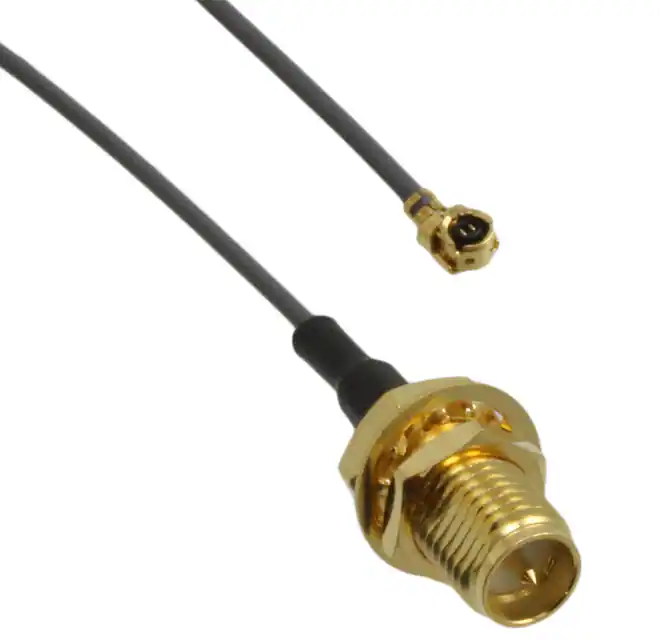
- Part No.:
- RN-UFL-SMA6
- Manufacturer:
- Microchip Technology
- Category:
- Coaxial Cables (RF)
- Package:
- Datasheet:
-
 RN-UFL-SMA6.pdf
- Description:
- COAX CBL U.FL TO RP-SMA
- Quantity:
- Payment:

- Shipping:

Inventory:1,499
Please send an inquiry. Send us your inquiry, and we will respond immediately.
Product details
Overview
RN-UFL-SMA6 from Roving Networks is a 6-inch coaxial RF cable assembly with UF.L (IPEX) male and reverse-polarity SMA female connectors, designed to interface the WiFly GSX RN-131G module with external antennas such as the RN-SMA-RA. It supports 2.4 GHz ISM band operation, delivers ≤0.8 dB insertion loss at 2.45 GHz, and maintains 50 Ω impedance for reliable Bluetooth and Wi-Fi signal transfer in embedded wireless gateways.
For engineers reviewing the RN-UFL-SMA6 datasheet, RN-UFL-SMA6 pinout, RN-UFL-SMA6 application, or RN-UFL-SMA6 equivalent, key selection criteria include RF loss budget, connector polarity compatibility with host modules and antennas, mechanical length constraints in compact enclosures, and 2.4 GHz impedance stability across temperature.
Technical Context
The RN-UFL-SMA6 serves as an impedance-matched RF interconnect between the U.FL/IPEX antenna port of the RN-131G WiFly GSX module and external reverse-polarity SMA antennas. Its construction uses low-loss micro-coax with silver-plated copper conductors and PE dielectric to preserve signal integrity.
It operates exclusively in the 2.40–2.4835 GHz band, with return loss ≥15 dB and VSWR ≤1.4:1 at center frequency. The cable is rated for 500 mating cycles on the U.FL end and features strain relief at both terminations to prevent connector detachment during vibration or flexing.
Key Specifications
| Parameter | Value and Actual Design Meaning |
|---|---|
| Length | 6 inches (152 mm); enables routing from PCB-mounted module to chassis-mounted antenna without excessive bend radius violation. |
| Frequency Range | 2.40–2.4835 GHz; fully covers IEEE 802.11b/g/n and Bluetooth BR/EDR bands. |
| Insertion Loss | ≤0.8 dB at 2.45 GHz; limits RF power degradation between module and antenna to <20%. |
| Impedance | 50 Ω nominal; ensures minimal reflection when connected to standard 50 Ω RF ports on RN-131G and RN-SMA-RA. |
| Connectors | UF.L (IPEX) male + reverse-polarity SMA female; matches RN-131G's onboard antenna pad and RN-SMA-RA's input port. |
| VSWR | ≤1.4:1 at 2.45 GHz; guarantees >85% power transfer efficiency under matched conditions. |
Availability
RN-UFL-SMA6 is available at Aetrix Electronics and suitable for Wi-Fi gateway integration, Bluetooth serial bridge deployment, and industrial IoT edge node development requiring stable component supply and repeatable RF performance.
Supply support for RN-UFL-SMA6 includes scheduled delivery planning, volume procurement assistance, BOM continuity management, traceable sourcing, and lifecycle availability coordination for OEM customers, industrial embedded developers, connected-device designers, and electronics production programs.
Manufacturer
Roving Networks was a fabless semiconductor company specializing in embedded wireless connectivity solutions, acquired by Microchip Technology in 2012. It focused on simplifying Wi-Fi and Bluetooth integration for resource-constrained microcontroller systems.
The RN-UFL-SMA6 belongs to Roving Networks' certified antenna interface accessory line, engineered specifically to maintain regulatory-compliant radiated performance when extending the RN-131G module's RF path beyond its PCB footprint.
FAQ
What is the primary function of the RN-UFL-SMA6?
The RN-UFL-SMA6 is a fixed-length RF coaxial cable that bridges the U.FL antenna port of the RN-131G WiFly GSX module to an external reverse-polarity SMA antenna. It preserves 50 Ω impedance and low insertion loss to ensure compliant radiated output power and receive sensitivity-critical for FCC/CE certification of end devices using the RN-UFL-SMA6 with the RN-131G.
Can the RN-UFL-SMA6 be used with modules other than the RN-131G?
The RN-UFL-SMA6 is mechanically and electrically optimized for the RN-131G's U.FL footprint and 2.4 GHz RF characteristics. While it may physically connect to other U.FL–SMA-RP interfaces, its validated performance-including insertion loss, VSWR, and bend tolerance-is documented only for use with the RN-131G and RN-SMA-RA antenna. Substitution requires independent RF validation.
Does the RN-UFL-SMA6 support both Wi-Fi and Bluetooth protocols?
Yes-the RN-UFL-SMA6 supports both Wi-Fi (802.11b/g/n) and Bluetooth (BR/EDR) because it operates across the full 2.40–2.4835 GHz ISM band with flat loss response and stable 50 Ω impedance. Its design enables simultaneous dual-mode operation when used with the RN-131G, which integrates both protocols in a single module.
Is reverse-polarity SMA required on the antenna side?
Yes-the RN-UFL-SMA6 terminates in a reverse-polarity SMA female connector, which must mate with a reverse-polarity SMA male antenna (e.g., RN-SMA-RA). Standard SMA polarity will not thread correctly and risks damaging threads or causing intermittent connection. Polarity mismatch prevents secure mechanical coupling and degrades RF shielding.
What is the maximum recommended bending radius for the RN-UFL-SMA6?
The RN-UFL-SMA6 has a minimum bend radius of 5 mm per manufacturer guidelines. Exceeding this-especially near the U.FL connector-risks conductor deformation, impedance discontinuity, or solder joint fracture on the RN-131G PCB. Routing should avoid sharp folds or compression under mounting hardware to maintain specified insertion loss and VSWR.
RN-UFL-SMA6 Specifications
- Product attributes
- Attribute value
- Manufacturer:
- Microchip Technology
- Series:
- -
- Packaging:
- Bag
- Product Status:
- Active
- Style:
- U.FL (UMCC) to RP-SMA
- 1st Connector:
- RP-SMA Jack
- 1st Contact Gender:
- Male
- 1st Connector Mounting Type:
- Panel Mount
- 1st Connector Mounting Feature:
- Bulkhead - Front Side Nut
- 2nd Connector:
- U.FL (UMCC) Plug, Right Angle
- 2nd Contact Gender:
- Female
- 2nd Connector Mounting Type:
- Free Hanging (In-Line)
- 2nd Connector Mounting Feature:
- -
- Length:
- 6.000" (152.40mm)
- Cable Type:
- 1.13mm OD Coaxial Cable
- Cable Impedance:
- -
- Connector Impedance:
- -
- Overall Impedance:
- 50 Ohms
- Frequency - Max:
- 5 GHz
- Color:
- Gray
- Features:
- Shielded
- Operating Temperature:
- -
- Grade:
- -
- Qualification:
- -
RN-UFL-SMA6 FAQ
1.How can I place an order for RN-UFL-SMA6 through Aetrix?
Please submit a Request for Quotation (RFQ) for RN-UFL-SMA6 on Aetrix. Our sales agent will provide a competitive quotation and guide you through the order confirmation once you accept the terms.
2.Are the price and stock information for RN-UFL-SMA6 reliable?
The price and inventory of RN-UFL-SMA6 are updated periodically and may fluctuate due to market conditions. Stock and pricing data are typically refreshed every 24 hours. Quotation validity for RN-UFL-SMA6 is usually 5 days.
3.What payment methods are accepted for RN-UFL-SMA6?
We accept Wire Transfer, PayPal, Credit Card, Western Union, MoneyGram, and Escrow for RN-UFL-SMA6 transactions.
Note: Certain payment methods may incur a processing fee.
4.How is shipping managed for RN-UFL-SMA6?
RN-UFL-SMA6 orders can be shipped via leading logistics carriers, including DHL, UPS, FedEx, TNT, or Registered Mail.
Once your RN-UFL-SMA6 order is processed, you will receive an email with the shipment details and tracking number.
Note: Tracking information may take up to 24 hours to appear. Express delivery typically takes 3–5 business days.
5.How can I obtain technical support or documentation for RN-UFL-SMA6?
For technical support, including RN-UFL-SMA6 datasheets, pinout diagrams, or application guidance, please contact our engineering support team. They can provide detailed documentation and assistance for your RN-UFL-SMA6 requirements.
6.How does Aetrix verify that RN-UFL-SMA6 is sourced from the original manufacturer or authorized distributors?
All RN-UFL-SMA6 products on Aetrix are procured from qualified distributors and authorized channels. Our dedicated quality assurance team conducts strict verification, including traceability checks and, if necessary, third-party testing. This ensures that RN-UFL-SMA6 meets industry standards.
7.What is the process for return or replacement of RN-UFL-SMA6?
All RN-UFL-SMA6 units undergo pre-shipment inspection (PSI). If there is an issue with RN-UFL-SMA6, returns or replacements are accepted under the following conditions:
1.Quantity discrepancies, incorrect items, or visible external defects (such as breakage or corrosion), acknowledged by Aetrix.
2.The issue is reported within 90 days of delivery.
3.The RN-UFL-SMA6 part is unused and in its original packaging.
Return procedure for RN-UFL-SMA6:
1.Submit a request within 90 days.
2.Obtain a Return Material Authorization (RMA) from Aetrix.
RN-UFL-SMA6 Tags
-
2015699-1
TE Connectivity AMP Connectors
-
WRL-18568
SparkFun Electronics

-
DH-20G50010
Cvilux USA
-
415-0108-250
Cinch Connectivity Solutions Johnson
-
CSI-UFFR-100-UFFR
TE Connectivity Linx
-
2015357-4
TE Connectivity AMP Connectors
-
CABLE 348 RF-050-A-1
GradConn
-
2015357-3
TE Connectivity AMP Connectors
-
0731160044
Molex
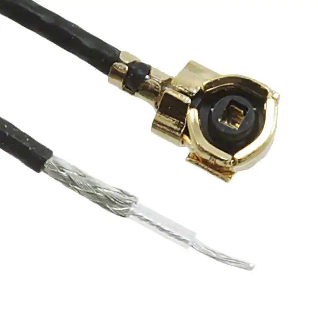
-
0731160074
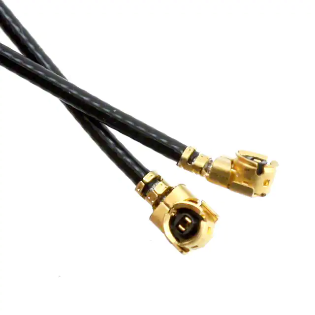
Molex
-
415-0086-050
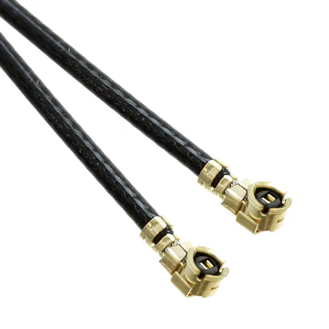
Cinch Connectivity Solutions Johnson
-
415-0088-050
Cinch Connectivity Solutions Johnson
Tech Hub

TTL and CMOS logic families differ in thresholds, loading, output drive, power and timing. This engineering guide compares 74HC and 74HCT, calculates noise margins and checks 3.3 V/5 V compatibility.

A practical engineering guide to 3.3V and 5V logic compatibility, input thresholds, resistor dividers, translator ICs, MOSFET level shifting, I2C pull-ups, timing limits and power-sequencing risks.

The 74HC595 uses push-pull logic outputs, while the TPIC6B595 uses 50 V open-drain DMOS sinks for higher-power loads. This guide compares timing, current limits, 3.3 V interfacing, load wiring, thermal…

The 74HC595 converts serial data into eight stable parallel outputs. This guide covers pin functions, shift and storage timing, OE and MR behavior, drive-current limits, cascading, voltage compatibilit…

A technical comparison of level-sensitive latches and edge-triggered flip-flops, covering timing windows, setup and hold limits, master–slave operation, time borrowing, race-through, HDL inference and…

A D latch stores one bit while Enable controls when data can pass. This reference covers gate-level operation, truth tables, transparency, setup and hold timing, LE versus OE, common ICs and practical …

An SR latch stores one bit through cross-coupled feedback. This engineering reference covers NOR and NAND implementations, truth tables, forbidden-state recovery, gated operation, switch debouncing, fa…

Latch circuits retain one bit through feedback. This technical reference covers SR and D latches, truth tables, transparency, timing limits, latch-versus-flip-flop behavior, applications and common log…

An engineering guide to LED driver operation, constant-current and constant-voltage outputs, linear and switching topologies, dimming, IC selection, calculations, replacement compatibility, and fault c…

Operational amplifier guide covering op amp basics, feedback, ideal vs real op amps, common configurations, buffer circuits, offset, bias current, gain-bandwidth, slew rate, rail-to-rail limits and sel…


