Send an Inquiry

To receive a quote for your project, please fill in the following information, and we’ll get back to you promptly.

Name*
Company*
Email Address*
Phone/WhatsApp
Part Number*
Quantity*
Message
Submit Inventory List

Please fill in the following information, and we’ll get back to you promptly.

Name*
Company*
Email Address*
Phone/WhatsApp
Upload My List
Message

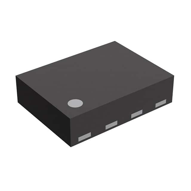
Nexperia USA Inc. RP115L301B-E2

Part No.:
RP115L301B-E2
Manufacturer:
Nexperia USA Inc.
Category:
Voltage Regulators - Linear, Low Drop Out (LDO) Regulators
Package:
8-XFDFN Exposed Pad
Datasheet:
AetrixRP115L301B-E2.pdf
Description:
RP115L - Low Voltage 500mA/1A LD
Quantity:
Payment:
Payment
Shipping:
Shipping

Inventory:10,000

Please send an inquiry. Send us your inquiry, and we will respond immediately.

Part Number
Quantity*
Price
Name*
Company
Email*
Comments

Product details

Overview

RP115L301B-E2 from Ricoh Electronics is a CMOS-based low-dropout linear regulator (LDO) in DFN1216-8 package, delivering 1.0 A output current with 3.0 V fixed output voltage, 0.195 V typical dropout at full load, ±1.0% output accuracy, and 80 dB ripple rejection at 1 kHz. It serves as a primary power source for battery-powered mobile communication equipment requiring stable low-noise voltage under tight space constraints.

For engineers reviewing the RP115L301B-E2 datasheet, RP115L301B-E2 pinout, RP115L301B-E2 application, or RP115L301B-E2 equivalent, key selection considerations include LCON-configurable current limit (500 mA/1.0 A), reverse current protection (VREV_REL = 30–50 mV), thermal shutdown at 165°C, CE active-high enable, and ceramic capacitor compatibility (≥1.0 µF).

Technical Context

The RP115L301B-E2 employs a P-channel MOSFET pass element with integrated reverse current protection circuitry that actively disables conduction when VOUT exceeds VIN by more than VREV_DET (20 mV), preventing backflow via internal gate control-distinct from passive parasitic diode conduction. Its constant-slope start-up circuit ensures 100 µs typical tON while limiting inrush current to 300 mA (LCON = "L") or 500 mA (LCON = "H").

Internal architecture includes a precision voltage reference, error amplifier, resistor network for fixed 3.0 V output, thermal shutdown (165°C trip, 110°C release), short-current limit (60 mA typ. at LCON = "L"), and auto-discharge–free CE control. The LCON pin enables dynamic selection between 500 mA and 1.0 A output current limits without changing external components.

Key Specifications

Parameter Value and Actual Design Meaning
Output Voltage Fixed 3.0 V ±1.0% (guaranteed over −40°C to +85°C, VSET ≥ 1.75 V)
Max Output Current 1.0 A (LCON = "H"); selectable to 500 mA (LCON = "L") for lower thermal stress
Dropout Voltage 0.195 V typ. at IOUT = 1.0 A, VOUT = 3.0 V - enables operation with VIN as low as 3.195 V
Ripple Rejection 80 dB typ. at 1 kHz, f ≤ 1.8 V output - suppresses switching noise from upstream DC/DC converters
Supply Current 110 µA typ. active; 0.5 µA typ. in standby - extends battery life in always-on sensor nodes
Thermal Shutdown 165°C junction trip temperature with 55°C hysteresis - protects against sustained overload or poor PCB heatsinking
Reverse Current Protection Active circuit blocks VOUT→VIN backfeed when ΔV = VIN−VOUT < −20 mV; releases at −30 to −50 mV

Pinout & Package

RP115L301B-E2 uses the DFN1216-8 (1.2 mm × 1.6 mm, 0.4 mm pitch) thermally enhanced package with exposed GND substrate tab. Pin 1–8 are arranged in standard DFN top-view layout; the bottom-side metal tab must be connected to PCB ground plane for optimal thermal performance and EMI suppression.

Pin/Terminal Circuit Role Design Meaning
1, 2 VOUT Regulated 3.0 V output; dual pins reduce IR drop and improve current handling
3 LCON Logic input selecting output current limit: "H" = 1.0 A, "L" = 500 mA; must remain stable during start-up
4 VFB Feedback node - internally tied to 3.0 V reference; not externally adjustable in this fixed-voltage variant
5 GND Power and signal ground reference; connects to exposed substrate tab for thermal path
6 CE Active-high chip enable; pulls output to 0 V when low; no auto-discharge (B-suffix)
7, 8 VDD Input supply (1.4–5.25 V); dual pins minimize input impedance and decoupling loop inductance

Key Features

Feature Design Value
Low Quiescent Current 110 µA active / 0.5 µA standby - enables >1-year battery life in IoT wake-on-event sensors
Ultra-Low Dropout 0.195 V @ 1.0 A - supports single-cell Li-ion (3.0–4.2 V) or 3.3 V rail regulation down to 3.195 V input
Reverse Current Blocking Active MOSFET-based protection - eliminates need for external blocking diode and its 0.3 V loss
Controlled Start-up Constant-slope tON = 100 µs typ. - prevents output overshoot and inrush-induced system reset
Robust Protection Suite Integrated thermal shutdown (165°C), short-circuit limit (60 mA LCON="L"), and overcurrent foldback

Applications

Smartphone Baseband Power Wearable Sensor Hub

Use Scenario: Powers RF transceiver ICs and baseband processors in LTE/5G smartphones where input voltage varies from 3.4 V (Li-ion nominal) to 4.2 V (fully charged).

IC Role / Device Role / Timing Role: Primary LDO delivering clean 3.0 V to noise-sensitive analog front-ends and PLLs; CE synchronized to modem sleep/wake cycles.

Use Value: 80 dB ripple rejection suppresses switching noise from PMIC buck converters; 0.195 V dropout preserves headroom during battery sag.

Use Scenario: Supplies 3.0 V to ultra-low-power motion sensors (accelerometer, gyroscope), BLE SoC, and EEPROM in fitness trackers.

IC Role / Device Role / Timing Role: Always-on LDO with CE-gated wake-up path; standby current of 0.5 µA minimizes quiescent drain during deep sleep.

Use Value: Dual VDD/VOUT pins reduce trace resistance; reverse current protection prevents battery discharge through shared VOUT rails during MCU reset.

Industrial Handheld Scanner Medical Point-of-Care Monitor

Use Scenario: Provides regulated 3.0 V to laser diode driver, image sensor, and microSD interface in rugged barcode scanners operating across −20°C to +70°C.

IC Role / Device Role / Timing Role: Main power regulator with LCON set to "H" for 1.0 A peak drive during laser pulse; thermal shutdown prevents damage during extended scanning.

Use Value: ±1.0% output accuracy ensures consistent ADC reference; 1.2 mm × 1.6 mm DFN footprint saves PCB area in compact handheld form factor.

Use Scenario: Powers ECG front-end amplifiers, OLED display controller, and wireless telemetry module in portable patient monitors with strict EMI and reliability requirements.

IC Role / Device Role / Timing Role: Low-noise LDO supplying analog signal chain; reverse current protection isolates VOUT from backup coin-cell during main power failure.

Use Value: 17×VSET µVrms output noise (51 µVrms at 3.0 V) meets medical-grade SNR targets; Pb-free/halogen-free construction complies with IEC 60601-1.

Equivalent & Alternatives

The following parts are listed as comparable options for similar LDO regulator applications.

Alternative Part Technical Difference Application Difference Selection Advice
Torex XC6210B302MR-G 3.0 V fixed, SOT-25 package, 500 mA max, 250 mV dropout @ 500 mA, no LCON or reverse current protection Lacks current-limit selectability and active reverse blocking - requires external diode for backfeed prevention Choose for cost-sensitive, lower-current designs where board space allows SOT-25 and thermal margin is sufficient
Ricoh RP114L301B-E2 Same DFN1216-8 package, 3.0 V fixed, but rated for 300 mA only; 220 mV dropout @ 300 mA; identical CE/LCON logic and protection features Lower current rating reduces thermal design burden but cannot support 1.0 A peak loads like camera flash or motor drivers Choose when system peak load stays below 300 mA and tighter thermal budget is required

Compared with XC6210B302MR-G, RP115L301B-E2 delivers 2× higher current and active reverse protection; versus RP114L301B-E2, it provides 3.3× higher output capability at identical footprint and feature set-making it optimal for space-constrained, high-current portable systems.

Availability

RP115L301B-E2 is available at Aetrix Electronics and suitable for smartphone power management, wearable sensor hubs, industrial handheld scanners, and medical point-of-care monitors requiring stable component supply with guaranteed long-term availability.

Supply support for RP115L301B-E2 includes scheduled delivery planning, volume procurement assistance, BOM continuity management, traceable sourcing, and lifecycle availability coordination for OEM customers, industrial embedded developers, connected-device designers, and electronics production programs.

Manufacturer

Ricoh Electronics is a Japanese semiconductor manufacturer specializing in high-efficiency power management ICs, including LDOs, DC/DC converters, and battery management solutions for mobile and industrial markets.

The RP115x series was designed specifically for battery-powered portable electronics demanding ultra-low quiescent current, low dropout, and robust protection-targeting applications where size, efficiency, and reliability are critical.

FAQ

What is the minimum input voltage required for RP115L301B-E2 to regulate 3.0 V output?

The recommended minimum input voltage is 1.4 V, but to maintain regulation at 3.0 V output with 1.0 A load, VIN must exceed VOUT + VDIF = 3.0 V + 0.195 V = 3.195 V. Below this, dropout occurs and output drops linearly with input. Absolute maximum VIN is 6.0 V.

Can RP115L301B-E2 be used with tantalum output capacitors?

No-tantalum capacitors with high ESR may cause instability due to insufficient phase margin. The RP115x series requires ceramic capacitors ≥1.0 µF (X5R/X7R dielectric) for guaranteed stability. Tantalum use demands extensive frequency-domain evaluation and is not recommended per design notes.

How does the LCON pin affect thermal performance during continuous 1.0 A operation?

When LCON = "H", the device delivers 1.0 A with 0.195 V dropout, dissipating up to 195 mW (P = VDIF × IOUT). In DFN1216-8 with proper PCB copper pour, junction temperature rise is ~45°C above ambient-well within the 125°C max rating if board thermal design meets JEDEC STD-51 guidelines.

Is reverse current protection active when the CE pin is low?

Yes-reverse current protection remains fully functional regardless of CE state. It operates independently based on VIN–VOUT differential and activates whenever VOUT exceeds VIN by more than VREV_DET (20 mV), even during standby mode with CE = low.

RP115L301B-E2 Specifications

Product attributes
Attribute value
Manufacturer:
Nexperia USA Inc.
Series:
RP115x
Package/Case:
8-XFDFN Exposed Pad
Packaging:
Bulk
Product Status:
Active
Output Configuration:
Positive
Output Type:
Fixed
Number of Regulators:
1
Voltage - Input (Max):
5.25V
Voltage - Output (Min/Fixed):
3V
Voltage - Output (Max):
-
Voltage Dropout (Max):
0.09V @ 500mA
Current - Output:
500mA
Current - Quiescent (Iq):
160 µA
Current - Supply (Max):
-
PSRR:
75dB (1kHz)
Control Features:
Enable
Protection Features:
Over Current, Over Temperature, Reverse Current
Operating Temperature:
-40°C ~ 85°C (TA)
Grade:
-
Qualification:
-
Mounting Type:
Surface Mount
Supplier Device Package:
DFN1216-8

RP115L301B-E2 FAQ

1.How can I place an order for RP115L301B-E2 through Aetrix?

Please submit a Request for Quotation (RFQ) for RP115L301B-E2 on Aetrix. Our sales agent will provide a competitive quotation and guide you through the order confirmation once you accept the terms.

2.Are the price and stock information for RP115L301B-E2 reliable?

The price and inventory of RP115L301B-E2 are updated periodically and may fluctuate due to market conditions. Stock and pricing data are typically refreshed every 24 hours. Quotation validity for RP115L301B-E2 is usually 5 days.

3.What payment methods are accepted for RP115L301B-E2?

We accept Wire Transfer, PayPal, Credit Card, Western Union, MoneyGram, and Escrow for RP115L301B-E2 transactions.

Note: Certain payment methods may incur a processing fee.

4.How is shipping managed for RP115L301B-E2?

RP115L301B-E2 orders can be shipped via leading logistics carriers, including DHL, UPS, FedEx, TNT, or Registered Mail.

Once your RP115L301B-E2 order is processed, you will receive an email with the shipment details and tracking number.

Note: Tracking information may take up to 24 hours to appear. Express delivery typically takes 3–5 business days.

5.How can I obtain technical support or documentation for RP115L301B-E2?

For technical support, including RP115L301B-E2 datasheets, pinout diagrams, or application guidance, please contact our engineering support team. They can provide detailed documentation and assistance for your RP115L301B-E2 requirements.

6.How does Aetrix verify that RP115L301B-E2 is sourced from the original manufacturer or authorized distributors?

All RP115L301B-E2 products on Aetrix are procured from qualified distributors and authorized channels. Our dedicated quality assurance team conducts strict verification, including traceability checks and, if necessary, third-party testing. This ensures that RP115L301B-E2 meets industry standards.

7.What is the process for return or replacement of RP115L301B-E2?

All RP115L301B-E2 units undergo pre-shipment inspection (PSI). If there is an issue with RP115L301B-E2, returns or replacements are accepted under the following conditions:

1.Quantity discrepancies, incorrect items, or visible external defects (such as breakage or corrosion), acknowledged by Aetrix.

2.The issue is reported within 90 days of delivery.

3.The RP115L301B-E2 part is unused and in its original packaging.

Return procedure for RP115L301B-E2:

1.Submit a request within 90 days.

2.Obtain a Return Material Authorization (RMA) from Aetrix.

RP115L301B-E2 Tags

  • RP115L301B-E2
  • RP115L301B-E2 PDF
  • RP115L301B-E2 Datasheet
  • RP115L301B-E2 Specifications
  • RP115L301B-E2 Images
  • Nexperia USA Inc.
  • Nexperia USA Inc. RP115L301B-E2
  • Buy RP115L301B-E2
  • RP115L301B-E2 Price
  • RP115L301B-E2 Distributor
  • RP115L301B-E2 Supplier
  • RP115L301B-E2 Wholesale
Related Products
MIC5504-1.8YM5-TR
MIC5504-1.8YM5-TR

Microchip Technology

MIC5504-3.3YM5-TR
MIC5504-3.3YM5-TR

Microchip Technology

MIC5365-3.0YC5-TR
MIC5365-3.0YC5-TR

Microchip Technology

MIC5365-1.8YC5-TR
MIC5365-1.8YC5-TR

Microchip Technology

MIC5365-2.5YC5-TR
MIC5365-2.5YC5-TR

Microchip Technology

MIC5365-3.3YC5-TR
MIC5365-3.3YC5-TR

Microchip Technology

MIC5365-3.3YD5-TR
MIC5365-3.3YD5-TR

Microchip Technology

MIC5317-3.3YM5-TR
MIC5317-3.3YM5-TR

Microchip Technology

TLV1117LV33DCYR
TLV1117LV33DCYR

Texas Instruments

MIC5317-3.3YMT-TZ
MIC5317-3.3YMT-TZ

Microchip Technology

MIC5528-3.3YMT-TR
MIC5528-3.3YMT-TR

Microchip Technology

TLV75801PDRVR
TLV75801PDRVR

Texas Instruments

Tech Hub

Search

Search

PRODUCT

PRODUCT

PHONE

PHONE

USER

USER