
 My Inquiry
 My Account


Infineon Technologies S25FL129P0XBHI303
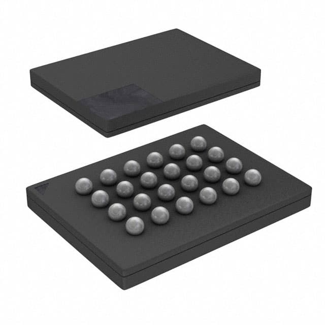
- Part No.:
- S25FL129P0XBHI303
- Manufacturer:
- Infineon Technologies
- Category:
- Memory
- Package:
- 24-TBGA
- Datasheet:
-
 S25FL129P0XBHI303.pdf
- Description:
- IC FLASH 128MBIT SPI/QUAD 24BGA
- Quantity:
- Payment:

- Shipping:

Inventory:4,810
Please send an inquiry. Send us your inquiry, and we will respond immediately.
Product details
Overview
S25FL129P0XBHI303 from Cypress Semiconductor is a 128-Mbit (16 MB), 3.0 V serial NOR Flash memory with uniform 64 KB sectors and dual/quad I/O support. It operates across 2.7–3.6 V, delivers up to 40 MB/s effective read throughput via Quad I/O FAST_READ, and integrates a 16-byte factory-programmable OTP area for secure device identification. Used in boot code storage for industrial microcontrollers and firmware update storage in network edge devices.
For engineers reviewing the S25FL129P0XBHI303 datasheet, S25FL129P0XBHI303 pinout, S25FL129P0XBHI303 application, or S25FL129P0XBHI303 equivalent, key selection criteria include sector architecture (64 KB uniform + 4 KB sub-sectors), W#/ACC-accelerated programming, Deep Power-Down current (3 µA), JEDEC-compliant Device ID, and CFI compliance for host auto-detection.
Technical Context
The S25FL129P0XBHI303 implements SPI-compatible serial interface with five extended command sets: Dual Output Read (DOR), Quad Output Read (QOR), Dual I/O Read (DIOR), Quad I/O Read (QIOR), and Quad Page Program (QPP). It supports both standard and accelerated programming modes - the latter enabled by applying 9 V to the W#/ACC pin - reducing typical page program time to 1.5 ms.
Memory organization includes two configurable layouts: 256 × 64 KB sectors (with top/bottom 64 KB sectors subdivided into thirty-two 4 KB sub-sectors) or 64 × 256 KB sectors. It maintains backward compatibility with S25FL128P while adding enhanced performance modes and OTP security features not present in legacy variants.
Key Specifications
| Parameter | Value and Actual Design Meaning |
|---|---|
| Memory Density | 128 Mbit (16 MB) - sufficient for full bootloader + firmware image storage in resource-constrained embedded systems |
| Supply Voltage | 2.7–3.6 V - single-supply operation compatible with 3.3 V system rails without level-shifting |
| Read Throughput | 40 MB/s (Quad I/O FAST_READ at 80 MHz) - enables fast code execution from XIP (execute-in-place) configurations |
| Page Program Time | 1.5 ms typical - reduces firmware update latency during field upgrades |
| Endurance & Retention | 100,000 program/erase cycles per sector / 20 years data retention - meets industrial lifecycle requirements |
| Power Modes | Standby: 80 µA; Deep Power-Down: 3 µA - supports ultra-low-power sleep states in battery-backed applications |
| OTP Capacity | 16 bytes (128-bit) factory- or customer-programmable - provides immutable hardware identity for secure boot binding |
Pinout & Package
Package: 8-contact WSON (6 × 8 mm, WNF008), RoHS-compliant, with exposed thermal pad (not electrically connected).
| Pin/Terminal | Circuit Role | Design Meaning |
|---|---|---|
| CS# | Chip Select | Active-low enable for SPI communication; required falling edge after power-up before command acceptance |
| SCK | Serial Clock | Drives timing for all SPI transactions; latches input on rising edge, outputs data on falling edge |
| SI/IO0 | Serial Input / I/O0 | Primary data input in standard mode; bidirectional I/O in Dual/Quad I/O and QPP modes |
| SO/IO1 | Serial Output / I/O1 | Primary data output in standard mode; bidirectional I/O in Dual/Quad I/O and QPP modes |
| W#/ACC/IO2 | Write Protect / Acceleration / I/O2 | Enables hardware write protection or 9 V-accelerated programming; serves as I/O2 in Quad modes |
| HOLD#/IO3 | Hold / I/O3 | Pauses ongoing SPI transfer without deselecting chip; functions as I/O3 in Quad I/O mode |
| VCC | Supply Voltage | 2.7–3.6 V main power rail; internally regulates voltages for program/erase operations |
| GND | Ground | Reference return path; must be low-impedance for stable read/write margins and noise immunity |
Key Features
| Feature | Design Value |
|---|---|
| Dual/Quad I/O Read Modes | Enables 2× or 4× bandwidth over standard SPI, supporting XIP from flash without external RAM buffering |
| Sub-sector Erase (4 KB) | Allows fine-grained firmware patching without erasing entire 64 KB sectors - critical for OTA updates |
| W#/ACC Accelerated Programming | Reduces page program time by >50% vs. standard mode when 9 V applied - improves production programming throughput |
| CFI Compliance | Permits automatic detection and configuration by host BIOS/bootloader without hard-coded driver logic |
| OTP Security Area | 16-byte one-time programmable space supports cryptographic key binding and anti-cloning measures |
Applications
| Industrial PLC Firmware Storage | Automotive ADAS Boot Memory |
|---|---|
Use Scenario: Storing real-time control firmware and configuration tables in programmable logic controllers operating in harsh temperature environments. IC Role / Device Role / Timing Role: Non-volatile boot memory providing deterministic read latency and sector-level update capability. Use Value: 64 KB uniform sectors enable atomic firmware rollback; 20-year data retention ensures reliability over 15+ year product lifecycles. |
Use Scenario: Holding boot code and safety-critical sensor calibration data for camera-based driver assistance modules. IC Role / Device Role / Timing Role: Secure, high-reliability SPI NOR used in ASIL-B compliant boot path with OTP-bound signature verification. Use Value: 16-byte OTP area binds firmware hash to hardware identity; sub-sector erase allows safe calibration updates without full reflash. |
| Network Edge Router Configuration | Medical Imaging Device Boot Loader |
Use Scenario: Hosting configuration scripts, TLS certificates, and fail-safe recovery images in carrier-grade Ethernet switches. IC Role / Device Role / Timing Role: Dual I/O-capable Flash supporting concurrent read/write during hot-failover transitions. Use Value: 80 µA standby current extends uptime during maintenance windows; CFI compliance simplifies multi-vendor firmware management. |
Use Scenario: Storing certified boot loader and DICOM protocol stack in portable ultrasound systems requiring FDA 510(k) traceability. IC Role / Device Role / Timing Role: Trusted boot source with locked OTP region ensuring unmodified bootloader integrity at power-on. Use Value: JEDEC-standard Device ID enables automated BOM validation; 100K-cycle endurance supports frequent regulatory firmware revisions. |
Equivalent & Alternatives
The following parts are listed as comparable options for similar serial NOR Flash memory applications.
| Alternative Part | Technical Difference | Application Difference | Selection Advice |
|---|---|---|---|
| S25FL128S | Successor device with identical density and voltage range but improved 133 MHz Quad I/O read speed and enhanced ECC support | Designed for new designs requiring higher throughput and stronger error resilience in mission-critical firmware storage | Select for new designs; migration path recommended by Cypress due to extended lifecycle and updated qualification |
| MX25L12833F | 128 Mbit, 3 V SPI NOR with 104 MHz FAST_READ but no Quad Page Program or W#/ACC acceleration | Lacks sub-sector erase and OTP security; suitable for cost-sensitive consumer applications without secure boot needs | Consider only where accelerated programming and hardware-secured identity are not required |
Compared with S25FL129P0XBHI303, S25FL128S offers higher read bandwidth and ECC, while MX25L12833F trades advanced features for lower unit cost - making the original part optimal for legacy industrial systems needing proven sub-sector flexibility and OTP binding.
Availability
S25FL129P0XBHI303 is available at Aetrix Electronics and suitable for industrial PLC firmware storage, automotive ADAS boot memory, and medical imaging device boot loader applications requiring stable component supply and long-term obsolescence management.
Supply support for S25FL129P0XBHI303 includes scheduled delivery planning, volume procurement assistance, BOM continuity management, traceable sourcing, and lifecycle availability coordination for OEM customers, industrial embedded developers, connected-device designers, and electronics production programs.
Manufacturer
Cypress Semiconductor, founded in 1982 and headquartered in San Jose, CA, delivers high-performance embedded solutions including PSoC, microcontrollers, analog ICs, and non-volatile memories for automotive, industrial, and consumer markets.
The S25FL129P belongs to Cypress's Spansion-branded serial NOR Flash family, engineered for reliable code storage and firmware update in systems demanding deterministic timing, sector-level granularity, and hardware-rooted security.
FAQ
Is S25FL129P0XBHI303 pin-compatible with S25FL128P?
Yes - S25FL129P0XBHI303 maintains identical pinout and electrical interface with S25FL128P, including SOIC-16, WSON-8, and BGA-24 packages. The device adds new commands (e.g., QPP, DIOR) but retains full backward compatibility for existing read/write/erase operations and status register layout.
What is the function of the W#/ACC pin beyond write protection?
The W#/ACC pin serves three roles: hardware write protection when pulled low, acceleration trigger for faster programming when 9 V is applied, and I/O2 signal in Quad I/O and Quad Page Program modes. Its dual functionality eliminates need for external acceleration circuitry in high-throughput programming fixtures.
Does S25FL129P0XBHI303 support execute-in-place (XIP) operation?
Yes - its Quad I/O FAST_READ mode achieves up to 40 MB/s effective throughput at 80 MHz clock rate, enabling direct code execution from flash in microcontrollers with SPI XIP capability. Latency is deterministic due to fixed command overhead and no internal cache dependency.
How is the OTP area secured against unauthorized access or reprogramming?
The 16-byte OTP region can be permanently locked using the LOCK_OTP command (0x42), which disables further writes to that area. Once locked, the OTP contents remain readable but cannot be altered - even by power cycling or reset - providing tamper-resistant hardware identity for secure boot chains.
S25FL129P0XBHI303 Specifications
- Product attributes
- Attribute value
- Manufacturer:
- Infineon Technologies
- Series:
- FL-P
- Package/Case:
- 24-TBGA
- Packaging:
- Tape & Reel (TR)
- Product Status:
- Obsolete
- Programmable:
- Not Verified
- Memory Type:
- Non-Volatile
- Memory Format:
- FLASH
- Technology:
- FLASH - NOR
- Memory Size:
- 128Mbit
- Memory Organization:
- 16M x 8
- Memory Interface:
- SPI - Quad I/O
- Clock Frequency:
- 104 MHz
- Write Cycle Time - Word, Page:
- 5µs, 3ms
- Access Time:
- -
- Voltage - Supply:
- 2.7V ~ 3.6V
- Operating Temperature:
- -40°C ~ 85°C (TA)
- Grade:
- -
- Qualification:
- -
- Mounting Type:
- Surface Mount
- Supplier Device Package:
- 24-BGA (6x8)
S25FL129P0XBHI303 FAQ
1.How can I place an order for S25FL129P0XBHI303 through Aetrix?
Please submit a Request for Quotation (RFQ) for S25FL129P0XBHI303 on Aetrix. Our sales agent will provide a competitive quotation and guide you through the order confirmation once you accept the terms.
2.Are the price and stock information for S25FL129P0XBHI303 reliable?
The price and inventory of S25FL129P0XBHI303 are updated periodically and may fluctuate due to market conditions. Stock and pricing data are typically refreshed every 24 hours. Quotation validity for S25FL129P0XBHI303 is usually 5 days.
3.What payment methods are accepted for S25FL129P0XBHI303?
We accept Wire Transfer, PayPal, Credit Card, Western Union, MoneyGram, and Escrow for S25FL129P0XBHI303 transactions.
Note: Certain payment methods may incur a processing fee.
4.How is shipping managed for S25FL129P0XBHI303?
S25FL129P0XBHI303 orders can be shipped via leading logistics carriers, including DHL, UPS, FedEx, TNT, or Registered Mail.
Once your S25FL129P0XBHI303 order is processed, you will receive an email with the shipment details and tracking number.
Note: Tracking information may take up to 24 hours to appear. Express delivery typically takes 3–5 business days.
5.How can I obtain technical support or documentation for S25FL129P0XBHI303?
For technical support, including S25FL129P0XBHI303 datasheets, pinout diagrams, or application guidance, please contact our engineering support team. They can provide detailed documentation and assistance for your S25FL129P0XBHI303 requirements.
6.How does Aetrix verify that S25FL129P0XBHI303 is sourced from the original manufacturer or authorized distributors?
All S25FL129P0XBHI303 products on Aetrix are procured from qualified distributors and authorized channels. Our dedicated quality assurance team conducts strict verification, including traceability checks and, if necessary, third-party testing. This ensures that S25FL129P0XBHI303 meets industry standards.
7.What is the process for return or replacement of S25FL129P0XBHI303?
All S25FL129P0XBHI303 units undergo pre-shipment inspection (PSI). If there is an issue with S25FL129P0XBHI303, returns or replacements are accepted under the following conditions:
1.Quantity discrepancies, incorrect items, or visible external defects (such as breakage or corrosion), acknowledged by Aetrix.
2.The issue is reported within 90 days of delivery.
3.The S25FL129P0XBHI303 part is unused and in its original packaging.
Return procedure for S25FL129P0XBHI303:
1.Submit a request within 90 days.
2.Obtain a Return Material Authorization (RMA) from Aetrix.
S25FL129P0XBHI303 Tags

-
M24C02-WMN6TP
STMicroelectronics

-
AT24C02C-XHM-T
Microchip Technology

-
AT21CS01-STUM10-T
Microchip Technology

-
AT24C02C-SSHM-T
Microchip Technology

-
24LC01BT-I/OT
Microchip Technology

-
M24C02-FMC6TG
STMicroelectronics
-
AT24CS02-SSHM-T
Microchip Technology

-
93LC46BT-I/OT
Microchip Technology
-
AT24C04C-SSHM-T
Microchip Technology

-
24LC01BT-I/SN
Microchip Technology
-
24AA02UIDT-I/OT
Microchip Technology

-
AT24C08C-STUM-T
Microchip Technology
Tech Hub

An engineering guide to LED driver operation, constant-current and constant-voltage outputs, linear and switching topologies, dimming, IC selection, calculations, replacement compatibility, and fault c…

Operational amplifier guide covering op amp basics, feedback, ideal vs real op amps, common configurations, buffer circuits, offset, bias current, gain-bandwidth, slew rate, rail-to-rail limits and sel…

Jumper cables guide covering safe connection order, red and black clamp placement, final ground connection, cable gauge, length, clamp quality, copper vs CCA cables, jump starter comparison and battery…

LDO regulator guide covering low dropout voltage, power dissipation, thermal design, PSRR, output noise, capacitor stability, adjustable LDO circuits, LDO vs buck converter and datasheet selection chec…

Conditional Access Module guide covering CAM meaning, CI/CI+ interface, smart card authorization, DVB security workflow, TV and set-top box compatibility, internal electronics, ESD protection, connecto…

Guide to electronic component obsolescence covering EOL risk, PCN/PDN notices, last-time buy planning, replacement options, form-fit-function validation, counterfeit risk and BOM lifecycle management.

18650 battery guide covering lithium-ion cell basics, 3.6V/3.7V voltage, 4.2V charging, mAh and Wh capacity, protected cells, chargers, BMS, series-parallel packs, holders, welding and sourcing checks.…

Hall effect sensor guide covering working principle, linear and digital sensors, Arduino circuits, current sensing, speed detection, automotive applications, A3144 examples, signal filtering and datash…

Product Change Notification guide for electronic components, covering PCN meaning, PCN vs PDN/EOL, common change types, risk levels, form-fit-function review, engineering validation, BOM control, LTB/L…

A practical guide to blend door actuators, covering HVAC function, symptoms, location, AC and heater issues, reset and calibration, replacement cost, electrical diagnosis, compatibility checks, and rep…


