
 My Inquiry
 My Account


Infineon Technologies S71VS128RC0AHK4L0
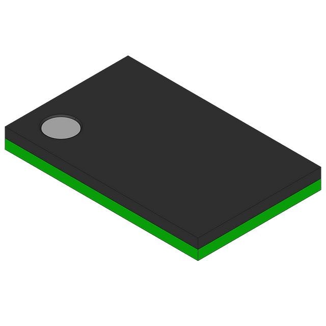
- Part No.:
- S71VS128RC0AHK4L0
- Manufacturer:
- Infineon Technologies
- Category:
- Memory
- Package:
- 56-VFBGA
- Datasheet:
-
 S71VS128RC0AHK4L0.pdf
- Description:
- IC FLSH RAM 128MBIT PAR 56VFRBGA
- Quantity:
- Payment:

- Shipping:

Inventory:3,141
Please send an inquiry. Send us your inquiry, and we will respond immediately.
Product details
Overview
S71VS128RC0AHK4L0 from Cypress Semiconductor is a 128 Mb MirrorBit Flash + 64 Mb pSRAM stacked Multi-Chip Package (MCP) operating at 1.7–1.95 V, supporting 108 MHz burst read/write, with 56-ball VFRBGA (7.7 × 6.2 mm, 0.5 mm pitch), designed for wireless handsets requiring simultaneous nonvolatile storage and fast volatile memory access.
For engineers reviewing the S71VS128RC0AHK4L0 datasheet, S71VS128RC0AHK4L0 pinout, S71VS128RC0AHK4L0 application, or S71VS128RC0AHK4L0 equivalent, key selection factors include burst-mode timing compatibility, shared address/data multiplexing, boot configuration (Top Boot), industrial temperature range (–40 °C to +85 °C), and dual-die power sequencing requirements.
Technical Context
This MCP integrates a S29VS128R Flash die and SWM064D108M1R pSRAM die in a single package, sharing A/DQ[15:0], CLK, OE#, WE#, CE# (separate F-CE# and R-CE#), and AVD# signals. Address mapping differs per density: Flash uses A22 and A21–A16; pSRAM uses A22 and A21–A16 - enabling unified bus control with distinct chip enables.
The device supports asynchronous and burst read/write modes. In burst mode, CLK increments internal address counters after initial word output; RDY/WAIT polarity mismatch between Flash (active-high RDY) and pSRAM (active-high WAIT) is resolved via Bus Configuration Register bit 10 or Flash Configuration Register bit 10, ensuring synchronized data valid timing.
Key Specifications
| Parameter | Value and Actual Design Meaning |
|---|---|
| Flash Density | 128 Mb - provides sufficient code storage for feature-rich mobile firmware with space for OTA updates |
| pSRAM Density | 64 Mb - delivers low-latency, battery-efficient working memory for real-time baseband or UI processing |
| Burst Speed | 108 MHz - enables 216 MB/s peak throughput on 16-bit multiplexed bus, meeting 3G/4G modem bandwidth needs |
| Supply Voltage | 1.7 V to 1.95 V - compatible with modern PMIC LDO outputs and reduces dynamic power vs. 3.3 V solutions |
| Operating Temp | –40 °C to +85 °C - qualified for industrial-grade handset and telematics applications without derating |
| Package | VFRBGA, 56-ball, 7.7 × 6.2 mm, 0.5 mm pitch - enables compact PCB layout with fine-pitch routing and thermal management |
| Boot Configuration | Top Boot - ensures secure boot vector location and simplifies bootloader initialization sequence |
Pinout & Package
Package: Very Thin Fine-Pitch Ball Grid Array (VFRBGA), 56-ball, 7.7 mm × 6.2 mm, 0.5 mm ball pitch, 1.0 mm max height, Pb-free, low-halogen.
| Pin/Terminal | Circuit Role | Design Meaning |
|---|---|---|
| A/DQ[15:0] | Multiplexed Address/Data I/O (shared) | Reduces pin count by time-multiplexing address setup and data transfer; requires external latch or controller support for ADM protocol |
| F-CE# / R-CE# | Separate Flash and pSRAM chip enables | Enables independent activation of Flash or pSRAM on same bus; prevents unintended writes during concurrent access |
| F-RDY/R-WAIT | Combined ready/wait open-drain output | Shared signal with configurable polarity; must be aligned via register bit 10 to avoid bus stall during mixed-mode operation |
| CLK | Burst mode clock input | Drives internal address counter only in burst mode; ignored in asynchronous mode - allows flexible timing control |
| R-LB#/R-UB# | pSRAM byte lane controls | Enable selective 8-bit writes to lower/upper byte lanes - critical for efficient packet buffer management |
Key Features
| Feature | Design Value |
|---|---|
| Simultaneous Read/Write Burst Mode | Allows concurrent Flash code execution and pSRAM data buffering - eliminates wait states in interrupt-driven real-time tasks |
| MirrorBit® 65 nm Flash Technology | Delivers high endurance (>100K program/erase cycles) and data retention (>20 years) in ultra-thin package |
| Address/Data Multiplexing (ADM) | Reduces total interface pins by 50% vs. non-multiplexed design - saves PCB layers and routing complexity |
| Dual-Die Power Sequencing Support | VCC and VCCQ supplied independently but within specified ramp time - simplifies PMIC integration without external sequencing logic |
| Top Boot Block Architecture | Protects boot code region from accidental erase; enables secure firmware update via protected sector locking |
Applications
| Smartphone Baseband Processing | Industrial Telematics Module |
|---|---|
Use Scenario: Real-time LTE protocol stack execution with frequent firmware patch loading and packet buffering. IC Role / Device Role / Timing Role: Flash stores boot image and modem firmware; pSRAM serves as low-power scratchpad for MAC/PHY layer buffers. Use Value: 108 MHz burst read avoids CPU stalls during instruction fetch; shared ADM bus minimizes SoC pin count and PCB area. | Use Scenario: GPS/IMU sensor fusion and CAN message logging in vehicle black-box systems operating across extended temperature ranges. IC Role / Device Role / Timing Role: Flash retains calibrated sensor models and event logs; pSRAM buffers real-time IMU samples before compression and storage. Use Value: –40 °C to +85 °C rating ensures reliability in under-hood environments; Top Boot architecture protects critical boot code from corruption. |
| Wireless IoT Gateway | Medical Portable Monitor |
Use Scenario: Concurrent Zigbee/Z-Wave protocol stacks with over-the-air update capability and local cache for edge analytics. IC Role / Device Role / Timing Role: Flash hosts multiple radio firmware images and secure boot keys; pSRAM holds active session buffers and encryption context. Use Value: Dual-die isolation prevents SRAM data leakage during Flash erase; 1.8 V operation extends battery life in battery-powered gateways. | Use Scenario: ECG waveform acquisition and display with real-time arrhythmia detection algorithms requiring deterministic memory access. IC Role / Device Role / Timing Role: Flash stores FDA-cleared algorithm binaries and calibration tables; pSRAM provides zero-wait-state buffer for 1 kHz sampled waveform data. Use Value: Burst-mode latency <15 ns meets real-time processing deadlines; VFRBGA package enables compact, high-density medical PCB layout. |
Equivalent & Alternatives
The following parts are listed as comparable options for similar Flash + pSRAM MCP applications.
| Alternative Part | Technical Difference | Application Difference | Selection Advice |
|---|---|---|---|
| S71VS128RB0AHK3L | 64 Mb pSRAM (vs. 64 Mb), same Flash density; 108 MHz speed; 56-ball package; Wireless temp (–25 °C to +85 °C) | Lacks industrial temperature rating; intended for consumer handset use only | Select when cost-sensitive consumer designs do not require extended temperature qualification |
| S71VS256RC0AHK4L | 256 Mb Flash + 64 Mb pSRAM; same package, speed, and temp range; higher Flash density increases code partitioning flexibility | Supports larger firmware images and dual-application storage (e.g., primary + recovery OS) | Choose when future-proofing for firmware growth or implementing secure dual-boot schemes |
Compared with S71VS128RB0AHK3L, this part adds industrial temperature support and Top Boot configuration; compared with S71VS256RC0AHK4L, it reduces Flash footprint and cost while maintaining identical pSRAM capacity and timing - ideal for cost-constrained industrial designs with fixed firmware size.
Availability
S71VS128RC0AHK4L0 is available at Aetrix Electronics and suitable for smartphone baseband modules, industrial telematics units, and portable medical monitors requiring stable component supply, long-term lifecycle assurance, and guaranteed industrial temperature compliance.
Supply support for S71VS128RC0AHK4L0 includes scheduled delivery planning, volume procurement assistance, BOM continuity management, traceable sourcing, and lifecycle availability coordination for OEM customers, industrial embedded developers, connected-device designers, and electronics production programs.
Manufacturer
Cypress Semiconductor, founded in 1982, delivers programmable SoCs, microcontrollers, analog ICs, connectivity solutions, and high-performance memories for automotive, industrial, and consumer applications.
The S71VS-R series belongs to Cypress's legacy Spansion MCP memory portfolio, engineered specifically for space-constrained wireless platforms needing integrated nonvolatile and volatile memory with burst-mode performance and industrial reliability.
FAQ
What is the correct power-up sequencing for S71VS128RC0AHK4L0?
VCC must stabilize before VCCQ, with both supplies reaching regulation within 100 ms. The recommended sequence is: apply VCC first, then VCCQ, followed by asserting F-RST# low for ≥100 µs after both supplies are stable. This ensures proper initialization of both Flash and pSRAM dies and avoids undefined state transitions.
How is RDY/WAIT polarity mismatch resolved between Flash and pSRAM?
The default Flash RDY (active-high) and pSRAM WAIT (active-high) have opposite valid states. Polarity alignment is achieved by writing '0' to bit 10 of the pSRAM Bus Configuration Register (to make WAIT active-low) or bit 10 of the Flash Configuration Register (to make RDY active-low). Both methods yield identical timing behavior.
Does S71VS128RC0AHK4L0 support asynchronous write operations?
Yes - asynchronous writes are supported on both Flash and pSRAM using WE#, OE#, and CE# control signals without CLK involvement. However, burst-mode writes require CLK edges to increment internal addresses; asynchronous mode is used for single-word programming or pSRAM byte-lane writes where precise timing control is needed.
What is the maximum allowable reflow temperature profile for the VFRBGA package?
The VFRBGA package is rated for JEDEC J-STD-020D-compliant reflow. Peak temperature must not exceed 260 °C for ≤30 seconds, with ramp-up rate ≤3 °C/s and ramp-down rate ≤6 °C/s. Exposure above 150 °C for prolonged periods risks solder joint integrity and die attach degradation - strict adherence to the profile is mandatory.
S71VS128RC0AHK4L0 Specifications
- Product attributes
- Attribute value
- Manufacturer:
- Infineon Technologies
- Series:
- VS-R
- Package/Case:
- 56-VFBGA
- Packaging:
- Tray
- Product Status:
- Obsolete
- Programmable:
- Not Verified
- Memory Type:
- Non-Volatile, Volatile
- Memory Format:
- FLASH, RAM
- Technology:
- FLASH, PSRAM
- Memory Size:
- 128Mbit (FLASH), 64Mbit (RAM)
- Memory Organization:
- -
- Memory Interface:
- Parallel
- Clock Frequency:
- 108 MHz
- Write Cycle Time - Word, Page:
- -
- Access Time:
- -
- Voltage - Supply:
- 1.7V ~ 1.95V
- Operating Temperature:
- -25°C ~ 85°C (TA)
- Grade:
- -
- Qualification:
- -
- Mounting Type:
- Surface Mount
- Supplier Device Package:
- 56-VFRBGA (7.7x6.2)
S71VS128RC0AHK4L0 FAQ
1.How can I place an order for S71VS128RC0AHK4L0 through Aetrix?
Please submit a Request for Quotation (RFQ) for S71VS128RC0AHK4L0 on Aetrix. Our sales agent will provide a competitive quotation and guide you through the order confirmation once you accept the terms.
2.Are the price and stock information for S71VS128RC0AHK4L0 reliable?
The price and inventory of S71VS128RC0AHK4L0 are updated periodically and may fluctuate due to market conditions. Stock and pricing data are typically refreshed every 24 hours. Quotation validity for S71VS128RC0AHK4L0 is usually 5 days.
3.What payment methods are accepted for S71VS128RC0AHK4L0?
We accept Wire Transfer, PayPal, Credit Card, Western Union, MoneyGram, and Escrow for S71VS128RC0AHK4L0 transactions.
Note: Certain payment methods may incur a processing fee.
4.How is shipping managed for S71VS128RC0AHK4L0?
S71VS128RC0AHK4L0 orders can be shipped via leading logistics carriers, including DHL, UPS, FedEx, TNT, or Registered Mail.
Once your S71VS128RC0AHK4L0 order is processed, you will receive an email with the shipment details and tracking number.
Note: Tracking information may take up to 24 hours to appear. Express delivery typically takes 3–5 business days.
5.How can I obtain technical support or documentation for S71VS128RC0AHK4L0?
For technical support, including S71VS128RC0AHK4L0 datasheets, pinout diagrams, or application guidance, please contact our engineering support team. They can provide detailed documentation and assistance for your S71VS128RC0AHK4L0 requirements.
6.How does Aetrix verify that S71VS128RC0AHK4L0 is sourced from the original manufacturer or authorized distributors?
All S71VS128RC0AHK4L0 products on Aetrix are procured from qualified distributors and authorized channels. Our dedicated quality assurance team conducts strict verification, including traceability checks and, if necessary, third-party testing. This ensures that S71VS128RC0AHK4L0 meets industry standards.
7.What is the process for return or replacement of S71VS128RC0AHK4L0?
All S71VS128RC0AHK4L0 units undergo pre-shipment inspection (PSI). If there is an issue with S71VS128RC0AHK4L0, returns or replacements are accepted under the following conditions:
1.Quantity discrepancies, incorrect items, or visible external defects (such as breakage or corrosion), acknowledged by Aetrix.
2.The issue is reported within 90 days of delivery.
3.The S71VS128RC0AHK4L0 part is unused and in its original packaging.
Return procedure for S71VS128RC0AHK4L0:
1.Submit a request within 90 days.
2.Obtain a Return Material Authorization (RMA) from Aetrix.
S71VS128RC0AHK4L0 Tags

-
M24C02-WMN6TP
STMicroelectronics

-
AT24C02C-XHM-T
Microchip Technology

-
AT21CS01-STUM10-T
Microchip Technology

-
AT24C02C-SSHM-T
Microchip Technology

-
24LC01BT-I/OT
Microchip Technology

-
M24C02-FMC6TG
STMicroelectronics
-
AT24CS02-SSHM-T
Microchip Technology

-
93LC46BT-I/OT
Microchip Technology
-
AT24C04C-SSHM-T
Microchip Technology

-
24LC01BT-I/SN
Microchip Technology
-
24AA02UIDT-I/OT
Microchip Technology

-
AT24C08C-STUM-T
Microchip Technology
Tech Hub

An engineering guide to LED driver operation, constant-current and constant-voltage outputs, linear and switching topologies, dimming, IC selection, calculations, replacement compatibility, and fault c…

Operational amplifier guide covering op amp basics, feedback, ideal vs real op amps, common configurations, buffer circuits, offset, bias current, gain-bandwidth, slew rate, rail-to-rail limits and sel…

Jumper cables guide covering safe connection order, red and black clamp placement, final ground connection, cable gauge, length, clamp quality, copper vs CCA cables, jump starter comparison and battery…

LDO regulator guide covering low dropout voltage, power dissipation, thermal design, PSRR, output noise, capacitor stability, adjustable LDO circuits, LDO vs buck converter and datasheet selection chec…

Conditional Access Module guide covering CAM meaning, CI/CI+ interface, smart card authorization, DVB security workflow, TV and set-top box compatibility, internal electronics, ESD protection, connecto…

Guide to electronic component obsolescence covering EOL risk, PCN/PDN notices, last-time buy planning, replacement options, form-fit-function validation, counterfeit risk and BOM lifecycle management.

18650 battery guide covering lithium-ion cell basics, 3.6V/3.7V voltage, 4.2V charging, mAh and Wh capacity, protected cells, chargers, BMS, series-parallel packs, holders, welding and sourcing checks.…

Hall effect sensor guide covering working principle, linear and digital sensors, Arduino circuits, current sensing, speed detection, automotive applications, A3144 examples, signal filtering and datash…

Product Change Notification guide for electronic components, covering PCN meaning, PCN vs PDN/EOL, common change types, risk levels, form-fit-function review, engineering validation, BOM control, LTB/L…

A practical guide to blend door actuators, covering HVAC function, symptoms, location, AC and heater issues, reset and calibration, replacement cost, electrical diagnosis, compatibility checks, and rep…


