
 My Inquiry
 My Account


NXP Semiconductors S912XEQ512J2MAAR
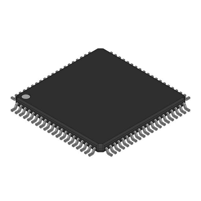
- Part No.:
- S912XEQ512J2MAAR
- Manufacturer:
- NXP Semiconductors
- Category:
- Microcontrollers
- Package:
- 80-QFP
- Datasheet:
-
 S912XEQ512J2MAAR.pdf
- Description:
- IC MCU 16BIT 512KB FLASH 80QFP
- Quantity:
- Payment:

- Shipping:

Inventory:3,228
Please send an inquiry. Send us your inquiry, and we will respond immediately.
Product details
Overview
S912XEQ512J2MAAR from NXP Semiconductors (formerly Freescale) is a 16-bit automotive microcontroller featuring the CPU12X core, 512 KB on-chip Flash memory with ECC, 32 KB RAM, and integrated MSCAN, XGATE co-processor, and enhanced ATD. It delivers full CAN performance in body control modules and gateway applications operating at -40°C to 125°C with 50 MHz bus frequency.
For engineers reviewing the S912XEQ512J2MAAR datasheet, S912XEQ512J2MAAR pinout, S912XEQ512J2MAAR application, or S912XEQ512J2MAAR equivalent, key selection criteria include Flash ECC support, XGATE offloading capability for CAN/LIN, 144-pin LQFP package compatibility, and automotive AEC-Q100 qualification status.
Technical Context
The S912XEQ512J2MAAR implements a 16-bit CPU12X core with full MC9S12 instruction set compatibility (excluding five fuzzy instructions), supports up to 50 MHz bus frequency, and integrates an enhanced XGATE co-processor running at 100 MHz that handles CAN mailbox management and LIN protocol stack independently of the main CPU.
It features Memory Protection Unit (MPU) with eight configurable address regions, ECC-enabled Flash with 1-bit correction/2-bit detection, and dual ATD converters offering 8/10/12-bit resolution across 16 analog inputs - all operating within automotive-grade temperature range (-40°C to 125°C) and supply voltage (3.3 V ±5% to 5.0 V +10%).
Key Specifications
| Parameter | Value and Actual Design Meaning |
|---|---|
| CPU Core | CPU12X 16-bit core, compatible with MC9S12 ISA (no MEM/WAV/REV instructions), enabling legacy code reuse without recompilation. |
| Flash Memory | 512 KB with ECC (64 data + 8 syndrome bits), supporting 1-bit fault correction and 2-bit fault detection for ASIL-B–capable system integrity. |
| RAM | 32 KB SRAM, accessible without wait states, suitable for real-time XGATE buffer and critical task stacks. |
| XGATE Co-processor | Programmable RISC engine running at 100 MHz, servicing MSCAN, LIN, SPI, and ATD interrupts without CPU intervention. |
| CAN Modules | 4-channel MSCAN (CAN0/CAN1/CAN2/CAN4), CAN 2.0A/B compliant, up to 1 Mbps bit rate, with FULL-CAN capability when paired with XGATE. |
| ATD Converter | Dual 8/10/12-bit ATD modules, 16-channel multiplexer, 3 µs 10-bit conversion time, internal oscillator support for Stop-mode operation. |
| Package | 144-pin LQFP (20 × 20 mm, 0.5 mm pitch), non-multiplexed external bus interface enabled, AEC-Q100 Grade 1 qualified. |
| Operating Temp | -40°C to 125°C ambient, supporting under-hood automotive deployment with robust EMC filtering via separate I/O and VREG supplies. |
Pinout & Package
144-pin LQFP (20 × 20 mm, 0.5 mm pitch, case no 918-03), with non-multiplexed external bus interface, dedicated BDM debug pin (BKGD), and dual power domains (VDDA/VDDIO).
| Pin/Terminal | Circuit Role | Design Meaning |
|---|---|---|
| BKGD | Background Debug | Single-wire BDM interface for non-intrusive flash programming and real-time debugging without halting CPU/XGATE execution. |
| RESET | Active-low Reset Input | Asynchronous reset assertion clears CPU registers, initializes MPU, and triggers COP watchdog reset recovery sequence. |
| XTAL/EXTAL | Crystal Oscillator Interface | Supports 4–16 MHz Pierce crystal (OSC_LCP); enables IPLL clock generation with spread-spectrum option for EMC reduction. |
| VDDA/VSSA | Analog Power/Ground | Isolated analog supply domain for ATD and internal voltage reference, minimizing digital noise coupling into precision conversions. |
| PORTH[7:0] | General-purpose I/O | 8-bit port with configurable pull-up/down, hysteresis, and drive strength; supports edge-sensitive wake-up from STOP/WAIT modes. |
| CS0–CS3 | Chip Select Outputs | Four independent chip selects for glue-less interface to external RAM/Flash; each configurable with timeout-based or EWAIT-driven transaction completion. |
Key Features
| Feature | Design Value |
|---|---|
| Memory Protection Unit (MPU) | 8 programmable address regions with 8-byte granularity, enforcing no-write/no-execute attributes and triggering NMI on violation - essential for ISO 26262 ASIL-B partitioning. |
| ECC-Protected Flash | 64-bit data + 8-bit syndrome per word enables real-time single-bit error correction during program execution, eliminating silent data corruption in safety-critical firmware. |
| XGATE Co-processor | Offloads CAN message handling (up to 32 mailboxes), LIN frame scheduling, and SPI/ATD DMA transfers - freeing CPU for application logic and reducing worst-case interrupt latency. |
| Enhanced MSCAN | Five receive buffers with FIFO, three prioritized transmit buffers, and 16-bit timestamping enable deterministic CAN communication for body control networks with >200 ms jitter tolerance. |
| Emulated EEPROM (EEE) | 4 KB D-Flash-based EEE with automated wear leveling, atomic write operations, and buffer RAM-to-D-Flash transfer on reset - eliminates need for external EEPROM in seat/mirror memory systems. |
| API Timer | Asynchronous Periodic Interrupt timer active in Full Stop mode, trimmable to ±10%, supports 0.2 ms–13 s intervals - ideal for low-power cyclic wake-up in door module sleep states. |
Applications
| Body Control Module (BCM) | Gateway Controller |
|---|---|
|
Use Scenario: Centralized control of lighting, window lifts, door locks, and HVAC actuators in modern vehicle body electronics. IC Role / Device Role / Timing Role: Primary MCU executing body control logic, managing PWM-driven power outputs, reading analog sensor inputs (temperature, humidity), and coordinating CAN/LIN communications. Use Value: XGATE handles 4× MSCAN traffic and LIN slave responses concurrently, reducing CPU load by ~45% versus standalone S12X; ECC Flash ensures firmware integrity over 15-year vehicle lifecycle. |
Use Scenario: Protocol translation and message routing between high-speed CAN-FD backbone and low-speed LIN subnetworks (e.g., mirror, seat, climate nodes). IC Role / Device Role / Timing Role: Dual-CAN/LIN interface MCU performing store-and-forward gateway functions with deterministic latency under 500 µs per message. Use Value: MPU-enforced memory isolation prevents CAN stack corruption from LIN driver faults; API timer enables 100 ms wake-up cycles for periodic diagnostics without battery drain. |
| Roof Module Controller | Seat Position Memory System |
|
Use Scenario: Integrated sunroof, panoramic roof, and rain sensor control with motor position feedback and obstacle detection. IC Role / Device Role / Timing Role: Real-time motion controller using ECT/PWM modules for bidirectional motor drive, ATD for current sensing, and CAN for status reporting. Use Value: Dual ATD converters enable simultaneous sampling of motor phase currents and thermistor voltages; 125°C rating allows placement near roof actuator motors. |
Use Scenario: Storing and recalling driver seat position, mirror angle, and steering column settings using non-volatile memory. IC Role / Device Role / Timing Role: EEE-managed memory controller writing position data to D-Flash with wear-leveling and power-fail-safe commit sequences. Use Value: Emulated EEPROM provides 100k-cycle endurance and automatic data migration on reset - eliminating external serial EEPROM and reducing BOM cost by $0.32/unit. |
Equivalent & Alternatives
The following parts are listed as comparable options for similar automotive microcontroller applications.
| Alternative Part | Technical Difference | Application Difference | Selection Advice |
|---|---|---|---|
| MC9S12XEP100MAL | 1 MB Flash, 64 KB RAM, 208-pin MAPBGA, 5 CAN modules, 8-channel ATD - larger memory and I/O count but incompatible pinout and package. | Targeted at high-end gateway or ADAS domain controllers requiring >768 KB code space and expanded peripheral concurrency. | Select only if design requires >512 KB Flash and can accommodate 208-pin BGA layout; not drop-in replaceable for S912XEQ512J2MAAR. |
| SPC560P50L5 | 32-bit Power Architecture core, 512 KB Flash, 48 KB RAM, 3 CAN FD, 1 LIN, AEC-Q100 Grade 1 - higher performance but different architecture and toolchain. | Suitable for next-generation body controllers migrating to CAN FD and requiring >100 DMIPS compute throughput. | Choose when upgrading from S12X platform to 32-bit; requires full software re-architecture and new compiler/debugger licensing. |
Compared with MC9S12XEP100MAL and SPC560P50L5, the S912XEQ512J2MAAR offers optimal balance of proven 16-bit deterministic timing, mature AUTOSAR-compatible tooling, and cost-effective 144-pin LQFP packaging - making it the preferred choice for volume production of mid-tier automotive body electronics where code size and CAN channel count are constrained to 512 KB and 4 channels.
Availability
S912XEQ512J2MAAR is available at Aetrix Electronics and suitable for automotive body control modules, gateway controllers, roof modules, and seat memory systems requiring stable component supply across extended product lifecycles.
Supply support for S912XEQ512J2MAAR includes scheduled delivery planning, volume procurement assistance, BOM continuity management, traceable sourcing, and lifecycle availability coordination for OEM customers, industrial embedded developers, connected-device designers, and electronics production programs.
Manufacturer
NXP Semiconductors is a global semiconductor leader specializing in secure connectivity solutions for automotive, industrial, and IoT applications, with deep heritage in automotive MCUs dating to Motorola's original 68HC11.
The S12XE family - including S912XEQ512J2MAAR - was designed specifically for automotive body electronics demanding functional safety, long-term supply stability, and seamless migration from legacy S12 platforms.
FAQ
What is the maximum bus frequency supported by the S912XEQ512J2MAAR?
The S912XEQ512J2MAAR supports a maximum CPU bus frequency of 50 MHz, achieved via its internal Frequency Modulated Phase Locked Loop (IPLL). This enables deterministic real-time execution for automotive body control tasks while maintaining compatibility with existing S12X peripheral timing models and legacy software drivers.
Does the S912XEQ512J2MAAR include hardware support for functional safety standards like ISO 26262?
Yes, the S912XEQ512J2MAAR includes MPU-enforced memory protection, ECC on Flash memory, and dual-lockstep-capable peripherals - features aligned with ASIL-B requirements. While not certified out-of-box, these capabilities form the foundational hardware layer required for ISO 26262-compliant system development when combined with appropriate software safety mechanisms and diagnostic libraries.
How many CAN interfaces does the S912XEQ512J2MAAR integrate, and what protocol versions are supported?
The S912XEQ512J2MAAR integrates four MSCAN modules (CAN0, CAN1, CAN2, CAN4), all compliant with CAN 2.0A and 2.0B protocols. Each supports standard and extended identifiers, programmable bit rates up to 1 Mbps, and FULL-CAN functionality when managed by the XGATE co-processor - enabling concurrent handling of >32 mailboxes without CPU overhead.
What package type and pin count does the S912XEQ512J2MAAR use?
The S912XEQ512J2MAAR uses a 144-pin LQFP package (20 × 20 mm body, 0.5 mm pitch, case number 918-03) with non-multiplexed external bus interface enabled. This package provides 119 usable I/O pins, supports external memory expansion, and is compatible with standard automotive PCB assembly processes and thermal management requirements.
Is the S912XEQ512J2MAAR qualified for automotive temperature ranges?
Yes, the S912XEQ512J2MAAR is qualified for operation from -40°C to 125°C ambient temperature (Grade 1 per AEC-Q100), with separate analog and I/O supply domains optimized for EMC performance in harsh automotive environments such as under-hood or door module locations.
S912XEQ512J2MAAR Specifications
- Product attributes
- Attribute value
- Manufacturer:
- NXP Semiconductors
- Package/Case:
- 80-QFP
- Series:
- HCS12X
- Packaging:
- Tape & Reel (TR)
- Product Status:
- Active
- Programmable:
- Not Verified
- Core Processor:
- HCS12X
- Core Size:
- 16-Bit
- Speed:
- 50MHz
- Connectivity:
- CANbus, EBI/EMI, I2C, IrDA, SCI, SPI
- Peripherals:
- LVD, POR, PWM, WDT
- Number of I/O:
- 59
- Program Memory Size:
- 512KB (512K x 8)
- Program Memory Type:
- FLASH
- EEPROM Size:
- 4K x 8
- RAM Size:
- 32K x 8
- Voltage - Supply (Vcc/Vdd):
- 1.72V ~ 5.5V
- Data Converters:
- A/D 8x12b
- Oscillator Type:
- External
- Operating Temperature:
- -40°C ~ 125°C (TA)
- Grade:
- -
- Qualification:
- -
- Mounting Type:
- Surface Mount
- Supplier Device Package:
S912XEQ512J2MAAR FAQ
1.How can I place an order for S912XEQ512J2MAAR through Aetrix?
Please submit a Request for Quotation (RFQ) for S912XEQ512J2MAAR on Aetrix. Our sales agent will provide a competitive quotation and guide you through the order confirmation once you accept the terms.
2.Are the price and stock information for S912XEQ512J2MAAR reliable?
The price and inventory of S912XEQ512J2MAAR are updated periodically and may fluctuate due to market conditions. Stock and pricing data are typically refreshed every 24 hours. Quotation validity for S912XEQ512J2MAAR is usually 5 days.
3.What payment methods are accepted for S912XEQ512J2MAAR?
We accept Wire Transfer, PayPal, Credit Card, Western Union, MoneyGram, and Escrow for S912XEQ512J2MAAR transactions.
Note: Certain payment methods may incur a processing fee.
4.How is shipping managed for S912XEQ512J2MAAR?
S912XEQ512J2MAAR orders can be shipped via leading logistics carriers, including DHL, UPS, FedEx, TNT, or Registered Mail.
Once your S912XEQ512J2MAAR order is processed, you will receive an email with the shipment details and tracking number.
Note: Tracking information may take up to 24 hours to appear. Express delivery typically takes 3–5 business days.
5.How can I obtain technical support or documentation for S912XEQ512J2MAAR?
For technical support, including S912XEQ512J2MAAR datasheets, pinout diagrams, or application guidance, please contact our engineering support team. They can provide detailed documentation and assistance for your S912XEQ512J2MAAR requirements.
6.How does Aetrix verify that S912XEQ512J2MAAR is sourced from the original manufacturer or authorized distributors?
All S912XEQ512J2MAAR products on Aetrix are procured from qualified distributors and authorized channels. Our dedicated quality assurance team conducts strict verification, including traceability checks and, if necessary, third-party testing. This ensures that S912XEQ512J2MAAR meets industry standards.
7.What is the process for return or replacement of S912XEQ512J2MAAR?
All S912XEQ512J2MAAR units undergo pre-shipment inspection (PSI). If there is an issue with S912XEQ512J2MAAR, returns or replacements are accepted under the following conditions:
1.Quantity discrepancies, incorrect items, or visible external defects (such as breakage or corrosion), acknowledged by Aetrix.
2.The issue is reported within 90 days of delivery.
3.The S912XEQ512J2MAAR part is unused and in its original packaging.
Return procedure for S912XEQ512J2MAAR:
1.Submit a request within 90 days.
2.Obtain a Return Material Authorization (RMA) from Aetrix.
S912XEQ512J2MAAR Tags

-
ATTINY4-TSHR
Microchip Technology
-
ATTINY10-TSHR
Microchip Technology
-
ATTINY10-TS8R
Microchip Technology

-
ATTINY202-SSNR
Microchip Technology
-
ATTINY202-SSFR
Microchip Technology
-
ATTINY402-SSNR
Microchip Technology

-
PIC16F15213T-I/MF
Microchip Technology
-
PIC16F15213-E/MF
Microchip Technology

-
PIC10F200T-I/OT
Microchip Technology
-
ATTINY412-SSNR
Microchip Technology
-
PIC10F202T-I/OT
Microchip Technology

-
ATTINY404-SSNR
Microchip Technology
Tech Hub

A practical engineering guide to 3.3V and 5V logic compatibility, input thresholds, resistor dividers, translator ICs, MOSFET level shifting, I2C pull-ups, timing limits and power-sequencing risks.

The 74HC595 uses push-pull logic outputs, while the TPIC6B595 uses 50 V open-drain DMOS sinks for higher-power loads. This guide compares timing, current limits, 3.3 V interfacing, load wiring, thermal…

The 74HC595 converts serial data into eight stable parallel outputs. This guide covers pin functions, shift and storage timing, OE and MR behavior, drive-current limits, cascading, voltage compatibilit…

A technical comparison of level-sensitive latches and edge-triggered flip-flops, covering timing windows, setup and hold limits, master–slave operation, time borrowing, race-through, HDL inference and…

A D latch stores one bit while Enable controls when data can pass. This reference covers gate-level operation, truth tables, transparency, setup and hold timing, LE versus OE, common ICs and practical …

An SR latch stores one bit through cross-coupled feedback. This engineering reference covers NOR and NAND implementations, truth tables, forbidden-state recovery, gated operation, switch debouncing, fa…

Latch circuits retain one bit through feedback. This technical reference covers SR and D latches, truth tables, transparency, timing limits, latch-versus-flip-flop behavior, applications and common log…

An engineering guide to LED driver operation, constant-current and constant-voltage outputs, linear and switching topologies, dimming, IC selection, calculations, replacement compatibility, and fault c…

Operational amplifier guide covering op amp basics, feedback, ideal vs real op amps, common configurations, buffer circuits, offset, bias current, gain-bandwidth, slew rate, rail-to-rail limits and sel…

Jumper cables guide covering safe connection order, red and black clamp placement, final ground connection, cable gauge, length, clamp quality, copper vs CCA cables, jump starter comparison and battery…


