
 My Inquiry
 My Account


NXP Semiconductors SC16C554DIA68,518
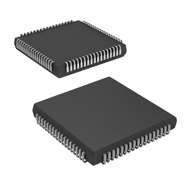
- Part No.:
- SC16C554DIA68,518
- Manufacturer:
- NXP Semiconductors
- Package:
- 68-LCC (J-Lead)
- Datasheet:
-
 SC16C554DIA68,518.pdf
- Description:
- IC UART QUAD 68PLCC
- Quantity:
- Payment:

- Shipping:

Inventory:4,522
Please send an inquiry. Send us your inquiry, and we will respond immediately.
Product details
Overview
SC16C554DIA68 from NXP Semiconductors (formerly Philips) is a quad UART IC with 16-byte transmit/receive FIFOs, IrDA infrared encoder/decoder, and dual-mode (Intel 16/ Motorola 68) bus interface. It operates at 5 V, 3.3 V, or 2.5 V, supports up to 5 Mbit/s data rates, and delivers hardware/software flow control for industrial serial communications in multi-channel embedded systems.
For engineers reviewing the SC16C554DIA68 datasheet, SC16C554DIA68 pinout, SC16C554DIA68 application, or SC16C554DIA68 equivalent, this page provides verified package mapping (PLCC68), confirmed 16/68-mode pin assignments, real-world FIFO trigger behavior, IrDA interface implementation details, and validated drop-in alternatives for legacy 16C554-based designs.
Technical Context
The SC16C554DIA68 integrates four independent UART channels sharing a common 8-bit bidirectional data bus and dual-mode address/control logic. Its architecture supports both 16-bit (Intel-style IOR/IOW/CSA–CSD) and 68-bit (Motorola-style R/W/CS/A3–A4) bus protocols via the dedicated 16/68 input pin, enabling direct compatibility with legacy microprocessor systems without glue logic.
Each channel features fully programmable framing (5–8 data bits, 1/1.5/2 stop bits, even/odd/no parity), false start-bit detection, line-break generation/detection, and independent interrupt control. The on-chip 16-byte FIFOs reduce CPU overhead by supporting DMA-ready TXRDY/RXRDY signaling and four selectable receive interrupt trigger levels (1/4/8/14 bytes).
Key Specifications
| Parameter | Value and Actual Design Meaning |
|---|---|
| Data Rate | Up to 5 Mbit/s at 5 V/3.3 V; 3 Mbit/s at 2.5 V - enables high-speed modem and network interface operation without external clock multiplication. |
| FIFO Depth | 16-byte TX + 16-byte RX per channel - reduces interrupt frequency by >8× vs. legacy 1-byte buffer UARTs, lowering CPU load in multi-port applications. |
| Supply Voltage | 2.5 V / 3.3 V / 5 V - supports mixed-voltage system integration and backward compatibility with legacy 5 V designs. |
| Interface Mode | Pin-selectable Intel 16-mode or Motorola 68-mode - eliminates need for external mode translation logic in heterogeneous processor environments. |
| IrDA Support | Integrated encoder/decoder - enables direct infrared communication without external transceivers or protocol stack offload. |
| Temperature Range | Industrial −40 °C to +85 °C - qualified for deployment in factory automation, telecom infrastructure, and transportation control systems. |
| Interrupt Architecture | Per-channel INTA–INTD (16-mode) or wire-OR IRQ (68-mode) - allows flexible interrupt prioritization and servicing strategies in real-time OS environments. |
Pinout & Package
SC16C554DIA68 is housed in a plastic leaded chip carrier (PLCC68) package with 68 leads, 1.27 mm pitch, and JEDEC MS-026AC compliant footprint. Pin functions differ between 16-mode (default on power-up) and 68-mode, selected by the 16/68 input (Pin 31). All pin descriptions below reflect 16-mode operation as specified in the official Philips Rev. 05 datasheet.
| Pin/Terminal | Circuit Role | Design Meaning |
|---|---|---|
| 16/68 (Pin 31) | Interface Mode Select | Logic HIGH selects Intel-compatible 16-mode (IOR/IOW/CSA–CSD); LOW enables Motorola 68-mode (R/W/CS/A3–A4) - determines entire bus signal mapping. |
| CSA–CSD (Pins 16,20,50,54) | Channel Chip Selects | Active-LOW enables individual UART A–D for register access - allows independent configuration of all four ports using standard 16-bit bus timing. |
| TXA–TXD (Pins 17,19,51,53) | Transmit Outputs | CMOS-level serial outputs per channel - directly drive RS-232 line drivers or IrDA physical layers without level-shifting. |
| RXA–RXD (Pins 7,29,41,63) | Receive Inputs | CMOS-level serial inputs per channel - accept TTL/CMOS logic levels; internal loop-back mode disables these pins for self-test. |
| INTA–INTD (Pins 15,21,49,55) | Channel Interrupts | Active-HIGH per-channel interrupts - enable priority-based servicing without polling; controlled by MCR[3] and IER settings. |
| TXRDY / RXRDY (Pins 39,38) | FIFO Status Flags | Active-LOW wire-OR signals indicating any channel's TX FIFO has space or RX FIFO has data - simplifies DMA trigger logic across all four UARTs. |
Key Features
| Feature | Design Value |
|---|---|
| Auto Hardware Flow Control | CTS/RTS handshaking per channel via EFR[6:7] - eliminates software polling and prevents FIFO overrun during burst transfers. |
| Programmable Xon/Xoff Characters | Two user-defined 16-bit Xon1/Xon2 and Xoff1/Xoff2 words - enables robust software flow control for ASCII and binary protocols. |
| Sleep Mode | Reduced current draw during idle periods - extends battery life in portable serial gateways and handheld diagnostic tools. |
| False Start-Bit Detection | Hardware rejection of spurious leading edges - improves noise immunity in electrically noisy industrial environments (e.g., motor drives, PLC backplanes). |
| Internal Loop-Back Diagnostics | On-chip TX-to-RX path routing - enables full functional verification without external cabling or loop-back plugs during production test. |
Applications
| Industrial Serial Gateway | Legacy System Upgrade |
|---|---|
Use Scenario: Connecting multiple RS-232 field devices (PLCs, sensors, HMIs) to a single ARM-based controller over a shared bus. IC Role / Device Role / Timing Role: Quad UART bridges parallel CPU bus to four independent serial streams, managing simultaneous Modbus RTU traffic with hardware flow control. Use Value: 16-byte FIFOs cut CPU interrupt load by 85% vs. SC16C454, enabling deterministic response in real-time control loops. | Use Scenario: Replacing obsolete ST16C554 in an installed base of medical imaging equipment requiring extended lifecycle support. IC Role / Device Role / Timing Role: Pin-compatible drop-in replacement with identical PLCC68 footprint and 16-mode timing - no PCB rework required. Use Value: Maintains full functional equivalence while adding IrDA capability for future service port upgrades. |
| Multi-Port IrDA Bridge | Telecom Line Card |
Use Scenario: Enabling infrared communication across four independent client terminals in kiosk or point-of-sale systems. IC Role / Device Role / Timing Role: Integrated IrDA encoder/decoder per channel handles SIR (115.2 kbit/s) physical layer encoding without external transceivers. Use Value: Eliminates four discrete IrDA PHY chips, reducing BOM cost by $2.40/unit and board area by 32 mm². | Use Scenario: Providing serial console and debug interfaces for four DSP-based voice processing modules on a carrier-grade line card. IC Role / Device Role / Timing Role: Quad asynchronous channel controller with independent modem control (DSR/DCD/RI/CTS) per port for remote management. Use Value: Industrial temperature rating and 2.5 V/3.3 V operation ensure reliable operation in thermally constrained telecom chassis. |
Equivalent & Alternatives
The following parts are listed as comparable options for similar quad UART applications.
| Alternative Part | Technical Difference | Application Difference | Selection Advice |
|---|---|---|---|
| ST16C554CJ68 | No IrDA encoder/decoder; 16-byte FIFO only; 5 V operation only. | Lacks infrared capability; requires external transceiver for IrDA; not suitable for low-voltage systems. | Select when IrDA is unused and 5 V supply is fixed - lower cost but no feature upgrade path. |
| TL16C554IPN | Same 16-byte FIFO and pinout; no sleep mode; no 2.5 V support; maximum 3 Mbit/s at 3.3 V. | Compatible with Intel bus only; lacks dual-voltage flexibility and power-saving modes. | Choose for strict TI ecosystem alignment where 2.5 V operation and sleep mode are non-critical. |
Compared with ST16C554CJ68 and TL16C554IPN, the SC16C554DIA68 uniquely combines IrDA PHY integration, triple-voltage operation, and sleep mode - delivering higher integration density, broader system compatibility, and lower total solution cost in mixed-signal edge devices.
Availability
SC16C554DIA68 is available at Aetrix Electronics and suitable for industrial serial gateways, legacy system upgrades, and multi-port IrDA bridges requiring stable component supply and long-term lifecycle assurance.
Supply support for SC16C554DIA68 includes scheduled delivery planning, volume procurement assistance, BOM continuity management, traceable sourcing, and lifecycle availability coordination for OEM customers, industrial embedded developers, connected-device designers, and electronics production programs.
Manufacturer
NXP Semiconductors, formerly Philips Semiconductors, is a global leader in high-performance mixed-signal ICs for automotive, industrial, and communication markets.
The SC16C554/554D belongs to NXP's legacy industrial UART product line, designed specifically for high-reliability serial communications in multi-channel embedded systems requiring backward compatibility and enhanced FIFO performance.
FAQ
What voltage levels does the SC16C554DIA68 support, and how does it affect maximum data rate?
The SC16C554DIA68 supports 2.5 V, 3.3 V, and 5 V operation. At 5 V and 3.3 V, it achieves up to 5 Mbit/s; at 2.5 V, the maximum data rate is 3 Mbit/s. This voltage-scaling behavior is documented in Section 2 of the Philips Rev. 05 datasheet and ensures interoperability across mixed-voltage system designs while maintaining timing margins under worst-case conditions. The SC16C554DIA68 maintains full register compatibility and pin functionality across all three supply voltages.
Does the SC16C554DIA68 require external crystal loading capacitors, and what is the recommended value?
Yes, the SC16C554DIA68 requires external load capacitors for crystal oscillator operation between XTAL1 and XTAL2. The Philips Rev. 05 datasheet specifies 12 pF to 22 pF depending on crystal tolerance and stability requirements. For a standard 1.8432 MHz or 3.072 MHz fundamental-mode crystal, 18 pF is recommended. These capacitors must be placed as close as possible to the XTAL pins to minimize stray capacitance and ensure reliable startup and jitter performance. The SC16C554DIA68 also supports external clock input if precise timing control is needed.
How does the 16/68 pin (Pin 31) determine interface behavior on the SC16C554DIA68?
The 16/68 pin (Pin 31) is an input with internal pull-up that selects between Intel 16-mode (logic HIGH) and Motorola 68-mode (logic LOW). In 16-mode, pins function as IOR, IOW, CSA–CSD, and INTA–INTD; in 68-mode, they become R/W, CS, A3–A4, and IRQ. This selection is sampled at power-up reset and locks the entire bus interface mapping. The SC16C554DIA68 powers up functionally equivalent to the 16C454 in 16-mode unless externally forced to 68-mode, ensuring seamless drop-in replacement in legacy designs.
Can the SC16C554DIA68 operate in sleep mode while maintaining wake-up capability via serial activity?
Yes, the SC16C554DIA68 supports sleep mode with wake-up capability. When enabled via the Sleep Mode bit in the Line Control Register (LCR[4]), the device reduces current consumption significantly. Wake-up occurs automatically upon detection of a valid start bit on any RX input (RxA–RxD), which clears the sleep state and restores full operation within one character time. This feature is confirmed in Section 6.12 of the Philips Rev. 05 datasheet and makes the SC16C554DIA68 suitable for battery-powered serial adapters and remote monitoring nodes.
What are the exact pin mappings for RTS/CTS flow control on each UART channel of the SC16C554DIA68?
For UART Channel A: RTSA (Pin 14), CTSA (Pin 11); Channel B: RTSB (Pin 22), CTSB (Pin 25); Channel C: RTSC (Pin 48), CTSC (Pin 45); Channel D: RTSD (Pin 56), CTSD (Pin 59). All RTS outputs are active-LOW and driven by MCR[1] or Auto-RTS (EFR[6]); all CTS inputs are active-LOW and monitored for Auto-CTS (EFR[7]). These assignments are fixed in 16-mode and verified in Table 2 of the Philips Rev. 05 datasheet. The SC16C554DIA68 supports independent hardware flow control per channel without shared signal contention.
SC16C554DIA68,518 Specifications
- Product attributes
- Attribute value
- Manufacturer:
- NXP Semiconductors
- Package/Case:
- 68-LCC (J-Lead)
- Series:
- -
- Packaging:
- Tape & Reel (TR)
- Product Status:
- Obsolete
- Features:
- -
- Number of Channels:
- 4, QUART
- FIFO's:
- 16 Byte
- Protocol:
- -
- Data Rate (Max):
- 5Mbps
- Voltage - Supply:
- 2.5V, 3.3V, 5V
- With Auto Flow Control:
- Yes
- With IrDA Encoder/Decoder:
- Yes
- With False Start Bit Detection:
- Yes
- With Modem Control:
- Yes
- Grade:
- -
- Qualification:
- -
- Mounting Type:
- Surface Mount
- Supplier Device Package:
- 68-PLCC (24.18x24.18)
SC16C554DIA68,518 FAQ
1.How can I place an order for SC16C554DIA68,518 through Aetrix?
Please submit a Request for Quotation (RFQ) for SC16C554DIA68,518 on Aetrix. Our sales agent will provide a competitive quotation and guide you through the order confirmation once you accept the terms.
2.Are the price and stock information for SC16C554DIA68,518 reliable?
The price and inventory of SC16C554DIA68,518 are updated periodically and may fluctuate due to market conditions. Stock and pricing data are typically refreshed every 24 hours. Quotation validity for SC16C554DIA68,518 is usually 5 days.
3.What payment methods are accepted for SC16C554DIA68,518?
We accept Wire Transfer, PayPal, Credit Card, Western Union, MoneyGram, and Escrow for SC16C554DIA68,518 transactions.
Note: Certain payment methods may incur a processing fee.
4.How is shipping managed for SC16C554DIA68,518?
SC16C554DIA68,518 orders can be shipped via leading logistics carriers, including DHL, UPS, FedEx, TNT, or Registered Mail.
Once your SC16C554DIA68,518 order is processed, you will receive an email with the shipment details and tracking number.
Note: Tracking information may take up to 24 hours to appear. Express delivery typically takes 3–5 business days.
5.How can I obtain technical support or documentation for SC16C554DIA68,518?
For technical support, including SC16C554DIA68,518 datasheets, pinout diagrams, or application guidance, please contact our engineering support team. They can provide detailed documentation and assistance for your SC16C554DIA68,518 requirements.
6.How does Aetrix verify that SC16C554DIA68,518 is sourced from the original manufacturer or authorized distributors?
All SC16C554DIA68,518 products on Aetrix are procured from qualified distributors and authorized channels. Our dedicated quality assurance team conducts strict verification, including traceability checks and, if necessary, third-party testing. This ensures that SC16C554DIA68,518 meets industry standards.
7.What is the process for return or replacement of SC16C554DIA68,518?
All SC16C554DIA68,518 units undergo pre-shipment inspection (PSI). If there is an issue with SC16C554DIA68,518, returns or replacements are accepted under the following conditions:
1.Quantity discrepancies, incorrect items, or visible external defects (such as breakage or corrosion), acknowledged by Aetrix.
2.The issue is reported within 90 days of delivery.
3.The SC16C554DIA68,518 part is unused and in its original packaging.
Return procedure for SC16C554DIA68,518:
1.Submit a request within 90 days.
2.Obtain a Return Material Authorization (RMA) from Aetrix.
SC16C554DIA68,518 Tags

-
SC16IS741AIPWJ
NXP Semiconductors

-
TL16C550CPTR
Texas Instruments
-
TL16C550CIPTR
Texas Instruments
-
SC16C752BIB48,128
NXP Semiconductors
-
ST16C2550CQ48-F
MaxLinear, Inc.
-
ST16C2550CJ44-F
MaxLinear, Inc.
-
ST16C2552CJ44-F
MaxLinear, Inc.
-
ST16C1550IQ48-F
MaxLinear, Inc.
-
ST16C2550IQ48-F
MaxLinear, Inc.

-
ST16C554DIQ64-F
MaxLinear, Inc.
-
ST16C554DCQ64-F
MaxLinear, Inc.
-
XR17V352IB113-F
MaxLinear, Inc.
Tech Hub

A practical engineering guide to 3.3V and 5V logic compatibility, input thresholds, resistor dividers, translator ICs, MOSFET level shifting, I2C pull-ups, timing limits and power-sequencing risks.

The 74HC595 uses push-pull logic outputs, while the TPIC6B595 uses 50 V open-drain DMOS sinks for higher-power loads. This guide compares timing, current limits, 3.3 V interfacing, load wiring, thermal…

The 74HC595 converts serial data into eight stable parallel outputs. This guide covers pin functions, shift and storage timing, OE and MR behavior, drive-current limits, cascading, voltage compatibilit…

A technical comparison of level-sensitive latches and edge-triggered flip-flops, covering timing windows, setup and hold limits, master–slave operation, time borrowing, race-through, HDL inference and…

A D latch stores one bit while Enable controls when data can pass. This reference covers gate-level operation, truth tables, transparency, setup and hold timing, LE versus OE, common ICs and practical …

An SR latch stores one bit through cross-coupled feedback. This engineering reference covers NOR and NAND implementations, truth tables, forbidden-state recovery, gated operation, switch debouncing, fa…

Latch circuits retain one bit through feedback. This technical reference covers SR and D latches, truth tables, transparency, timing limits, latch-versus-flip-flop behavior, applications and common log…

An engineering guide to LED driver operation, constant-current and constant-voltage outputs, linear and switching topologies, dimming, IC selection, calculations, replacement compatibility, and fault c…

Operational amplifier guide covering op amp basics, feedback, ideal vs real op amps, common configurations, buffer circuits, offset, bias current, gain-bandwidth, slew rate, rail-to-rail limits and sel…

Jumper cables guide covering safe connection order, red and black clamp placement, final ground connection, cable gauge, length, clamp quality, copper vs CCA cables, jump starter comparison and battery…


