
 My Inquiry
 My Account


Texas Instruments SCANSTA101SMX/NOPB
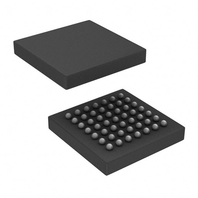
- Part No.:
- SCANSTA101SMX/NOPB
- Manufacturer:
- Texas Instruments
- Category:
- Specialized
- Package:
- 49-LFBGA
- Datasheet:
-
 SCANSTA101SMX/NOPB.pdf
- Description:
- IC INTERFACE SPECIALIZED 49BGA
- Quantity:
- Payment:

- Shipping:

Inventory:3,343
Please send an inquiry. Send us your inquiry, and we will respond immediately.
Product details
Overview
SCANSTA101SMX/NOPB from Texas Instruments is an IEEE 1149.1 System Test Access (STA) Master IC designed to serve as a boundary-scan test controller in embedded and stand-alone JTAG systems. It features a 16-bit parallel processor interface, 2k × 32-bit dual-port memory, on-board sequencer, 32-bit LFSR for signature analysis, and operates at 3.3 V with 5 V tolerant I/O - enabling high-throughput test vector execution in FPGA configuration and PCB-level diagnostics.
For engineers reviewing the SCANSTA101SMX/NOPB datasheet, SCANSTA101SMX/NOPB pinout, SCANSTA101SMX/NOPB application, or SCANSTA101SMX/NOPB equivalent, this device delivers deterministic TAP control, load-on-the-fly vector execution, hardware-accelerated compare validation, and register-based host interfacing - critical for production test automation, in-system programmable logic configuration, and debug infrastructure in industrial and telecom equipment.
Technical Context
The SCANSTA101SMX/NOPB implements a three-interface architecture: Parallel Processor Interface (PPI) for host CPU access, Serial Scan Interface (SSI) for IEEE 1149.1 TAP generation, and Test & Debug Interface supporting BIST, boundary scan, and internal scan. Its dual-port memory acts as a synchronous buffer between PPI and SSI, enabling concurrent host data loading and serial test execution.
It supports both asynchronous and synchronous processor timing via STB/CE handshaking, includes dedicated registers for vector indexing, macro sequencing, header/trailer handling, and LFSR seed/result management, and provides hardware-assisted TDI validation against expected data - reducing software overhead in embedded test firmware.
Key Specifications
| Parameter | Value and Actual Design Meaning |
|---|---|
| Supply Voltage | 3.0 V to 3.6 V - ensures compatibility with modern 3.3 V logic domains while tolerating 5 V I/O signals |
| Operating Temperature | −40°C to +85°C - qualified for industrial-grade embedded deployment without derating |
| Parallel Interface | 16-bit bidirectional data bus (D[15:0]) with address (A[4:0]), R/W, CE, STB, DTACK, INT - enables direct microcontroller connection without glue logic |
| Dual-Port Memory | 2048 × 32-bit - buffers test vectors, expected results, masks, macros, and sequencer instructions for pipelined execution |
| TAP Clock Support | Up to 25 MHz TCK - meets IEEE 1149.1 timing requirements for high-speed boundary scan testing |
| System Clock (SCK) | Up to 66 MHz - determines maximum PPI throughput and internal state machine speed |
| LFSR Engine | 32-bit linear feedback shift register at TDI port - performs real-time signature compression for test response validation |
Pinout & Package
SCANSTA101SMX/NOPB is housed in a 49-pin NFBGA package (7 mm × 7 mm, 0.8 mm pitch), optimized for high-density PCB layouts in test instrumentation and embedded controllers.
| Pin/Terminal | Circuit Role | Design Meaning |
|---|---|---|
| VCC | Power supply input | 3.3 V core supply; four pins ensure low-impedance power delivery and noise immunity |
| GND | Ground reference | Four dedicated ground pins minimize ground bounce during high-speed TAP transitions |
| D[15:0] | Bidirectional data bus | 16-bit parallel path for register/memory read/write; supports 16-bit microcontroller interfaces directly |
| A[4:0] | Address bus | 5-bit address space selects 32 registers and memory-mapped regions including Vector, Macro, Sequencer tables |
| SCK | System clock input | Drives all internal timing; gated/divided version (TCK_SM) feeds JTAG TAP controller |
| INT | Interrupt output | Active-low signal alerts host CPU upon completion of vector execution or error condition |
| OE | Output enable | Tri-states all 1149.1 outputs (TDO_SM, TMS_SM, TCK_SM, TRST0_SM) when high - enables shared TAP bus operation |
| DTACK | Data transfer acknowledge | Handshake signal confirms PPI register/memory access completion; supports asynchronous host timing |
| R/W | Read/write control | Determines direction of D[15:0] bus; high = read, low = write - eliminates need for external direction logic |
| STB | Strobe input | Edge-triggered control for PPI transfers; falling edge initiates access, rising edge completes setup/hold timing |
| CE | Chip enable | Enables PPI interface; allows back-to-back accesses without reassertion - improves burst throughput |
| RST | Asynchronous reset | Initializes all internal registers and state machines; required before first test sequence execution |
| TDI, TMS, TCK, TRST | JTAG primary interface | Standard IEEE 1149.1 inputs driving the Test & Debug Interface; TRST tied to GND via 1 kΩ resistor for safe power-up |
| TDI_SM, TDO_SM, TMS_SM, TCK_SM, TRST0_SM | STA Master TAP outputs | Generated JTAG signals driven to target scan chain; TRST0_SM is active-low reset for downstream devices |
| TRIST_SM | Tri-state notification | High when TDO_SM is tri-stated (e.g., during OE high) - enables safe bus sharing with other JTAG masters |
Key Features
| Feature | Design Value |
|---|---|
| On-board sequencer | Executes multi-vector operations (e.g., FPGA configuration sequences) without host CPU intervention - reduces test cycle time by >70% vs. software-driven TAP control |
| Hardware compare engine | Validates TDI data against preloaded expected values in real time - eliminates software polling and enables fail-fast detection |
| Load-on-the-fly (LotF) mode | Allows test vectors to be streamed into memory during execution - supports unlimited-length test sequences within available memory |
| State, Shift, and BIST macros | Predefined instruction sets for common JTAG operations (e.g., IDCODE capture, BYPASS entry) - simplifies firmware development and improves repeatability |
| 32-bit LFSR at TDI port | Performs signature compression on incoming test responses - enables compact pass/fail verification without storing full result streams |
Applications
| Automated PCB Functional Test | FPGA In-System Configuration |
|---|---|
Use Scenario: High-volume manufacturing line performing post-reflow continuity, shorts, and component presence checks on complex backplanes. IC Role / Device Role / Timing Role: SCANSTA101SMX/NOPB acts as the boundary-scan master, generating precise TCK/TMS/TTDI sequences synchronized to board-level clocks and validating TDO responses against golden signatures. Use Value: Reduces test fixture complexity by eliminating bed-of-nails probes for BGA packages and enables 100% net coverage on dense interconnects. |
Use Scenario: Field-upgradable telecom base station where FPGAs must be reconfigured without system reboot or physical access. IC Role / Device Role / Timing Role: SCANSTA101SMX/NOPB serves as the IEEE 1532-compliant configuration controller, loading bitstreams over JTAG using preloaded vectors and verifying CRC checksums via LFSR compression. Use Value: Enables secure, verified, and deterministic FPGA programming independent of host OS or driver stack - critical for carrier-grade reliability. |
| Embedded Debug Infrastructure | Multi-DUT JTAG Test Rack |
Use Scenario: Industrial PLC with integrated boundary-scan capability for runtime diagnostics and fault isolation during maintenance windows. IC Role / Device Role / Timing Role: SCANSTA101SMX/NOPB operates in embedded mode, executing diagnostic vectors triggered by watchdog timeout or user command via its register interface. Use Value: Provides deterministic, low-overhead visibility into ASIC and FPGA I/O states without requiring debug ports or JTAG adapters. |
Use Scenario: ATE system testing up to 8 PCBs simultaneously using shared JTAG resources and per-board SCANSTA101SMX/NOPB instances. IC Role / Device Role / Timing Role: SCANSTA101SMX/NOPB functions as a dedicated, isolated JTAG master per DUT, with OE-controlled TAP outputs preventing bus contention. Use Value: Eliminates multiplexer latency and signal integrity degradation in daisy-chained JTAG chains - improves test repeatability and throughput. |
Equivalent & Alternatives
The following parts are listed as comparable options for similar IEEE 1149.1 system test access applications.
| Alternative Part | Technical Difference | Application Difference | Selection Advice |
|---|---|---|---|
| Xilinx XAPP1079 IP Core | Soft IP for FPGA implementation only; no standalone NFBGA package; requires synthesis and integration into PL fabric | Targeted for designs where test logic must reside inside same FPGA being tested - not suitable for external test controller role | Select when test infrastructure must be fully embedded and reconfigurable; avoid when discrete, certified, and pin-defined STA master is required |
| Intellitech EmbeddedScan Controller | Supports IEEE 1149.1 and 1149.6; includes built-in ATPG support and higher-level test language (TDL); larger footprint and higher cost | Used in high-end ATE and automotive ECU validation where advanced diagnostics and failure analysis are mandatory | Select for mission-critical safety applications needing ISO 26262 tool qualification; avoid for cost-sensitive industrial or telecom use cases |
Compared with XAPP1079 and Intellitech EmbeddedScan, SCANSTA101SMX/NOPB offers fixed-function, silicon-proven STA control in a compact NFBGA with minimal host software dependency - making it optimal for deterministic, low-latency, and production-deployable boundary-scan systems where flexibility is secondary to reliability and ease of integration.
Availability
SCANSTA101SMX/NOPB is available at Aetrix Electronics and suitable for automated PCB functional test, FPGA in-system configuration, embedded debug infrastructure, and multi-DUT JTAG test rack applications requiring stable component supply, long-term lifecycle assurance, and traceable sourcing.
Supply support for SCANSTA101SMX/NOPB includes scheduled delivery planning, volume procurement assistance, BOM continuity management, traceable sourcing, and lifecycle availability coordination for OEM customers, industrial embedded developers, connected-device designers, and electronics production programs.
Manufacturer
Texas Instruments is a global semiconductor leader specializing in analog, embedded processing, and connectivity solutions, with decades of investment in test and debug infrastructure for programmable logic and complex SoCs.
The SCANSTA101SMX/NOPB belongs to TI's System Test Access product line, engineered specifically to accelerate IEEE 1149.1 adoption in cost-sensitive, high-reliability embedded systems - bridging the gap between software-driven JTAG tools and full-featured ATE platforms.
FAQ
What is the primary function of the SCANSTA101SMX/NOPB in a JTAG test system?
The SCANSTA101SMX/NOPB functions as a dedicated IEEE 1149.1 System Test Access (STA) Master, generating precise TAP controller signals (TCK_SM, TMS_SM, TDI_SM, TDO_SM) and managing test vector execution independently of the host processor. It offloads boundary-scan protocol timing and sequencing from software, enabling deterministic, high-throughput test execution in SCANSTA101SMX/NOPB-based systems.
Does the SCANSTA101SMX/NOPB support both 16-bit and 32-bit host interfaces?
The SCANSTA101SMX/NOPB implements a native 16-bit parallel processor interface (D[15:0], A[4:0]) with full register and memory mapping. While its internal dual-port memory is 32-bit wide and the IP macro version supports 32-bit expansion (D[31:16]), the packaged SCANSTA101SMX/NOPB device does not expose D[31:16] pins - confirming strict 16-bit host interface operation per its NFBGA pinout and datasheet specifications.
How does the SCANSTA101SMX/NOPB handle test vector comparison during execution?
The SCANSTA101SMX/NOPB includes dedicated hardware compare logic that validates incoming TDI_SM data against preloaded expected values stored in its dual-port memory. This comparison occurs in real time during vector execution, and the result triggers status flags and optional interrupts - eliminating software polling and enabling immediate fail detection without host CPU involvement in SCANSTA101SMX/NOPB operation.
Can the SCANSTA101SMX/NOPB operate with a 5 V microcontroller interface?
No - the SCANSTA101SMX/NOPB operates exclusively from a 3.3 V supply (VCC = 3.0–3.6 V) and is specified for 5 V tolerant I/O only on its JTAG output pins (TDO_SM, TMS_SM, etc.), not its parallel processor interface. Its D[15:0], A[4:0], R/W, CE, and STB pins require 3.3 V logic levels; interfacing with 5 V microcontrollers necessitates level-shifting circuitry for SCANSTA101SMX/NOPB compatibility.
What is the role of the TRST0_SM pin on the SCANSTA101SMX/NOPB?
TRST0_SM is an active-low output signal generated by the SCANSTA101SMX/NOPB to reset the Test Logic of downstream IEEE 1149.1 devices in the scan chain. It is distinct from the input TRST pin (which resets the SCANSTA101SMX/NOPB itself) and provides synchronized, hardware-controlled reset assertion to ensure predictable TAP state initialization across the entire JTAG chain during SCANSTA101SMX/NOPB startup or recovery sequences.
SCANSTA101SMX/NOPB Specifications
- Product attributes
- Attribute value
- Manufacturer:
- Texas Instruments
- Series:
- -
- Package/Case:
- 49-LFBGA
- Packaging:
- Tape & Reel (TR)
- Product Status:
- Active
- Applications:
- Testing Equipment
- Interface:
- IEEE 1149.1
- Voltage - Supply:
- 3V ~ 3.6V
- Supplier Device Package:
- 49-NFBGA (7x7)
- Grade:
- -
- Qualification:
- -
- Mounting Type:
- Surface Mount
SCANSTA101SMX/NOPB FAQ
1.How can I place an order for SCANSTA101SMX/NOPB through Aetrix?
Please submit a Request for Quotation (RFQ) for SCANSTA101SMX/NOPB on Aetrix. Our sales agent will provide a competitive quotation and guide you through the order confirmation once you accept the terms.
2.Are the price and stock information for SCANSTA101SMX/NOPB reliable?
The price and inventory of SCANSTA101SMX/NOPB are updated periodically and may fluctuate due to market conditions. Stock and pricing data are typically refreshed every 24 hours. Quotation validity for SCANSTA101SMX/NOPB is usually 5 days.
3.What payment methods are accepted for SCANSTA101SMX/NOPB?
We accept Wire Transfer, PayPal, Credit Card, Western Union, MoneyGram, and Escrow for SCANSTA101SMX/NOPB transactions.
Note: Certain payment methods may incur a processing fee.
4.How is shipping managed for SCANSTA101SMX/NOPB?
SCANSTA101SMX/NOPB orders can be shipped via leading logistics carriers, including DHL, UPS, FedEx, TNT, or Registered Mail.
Once your SCANSTA101SMX/NOPB order is processed, you will receive an email with the shipment details and tracking number.
Note: Tracking information may take up to 24 hours to appear. Express delivery typically takes 3–5 business days.
5.How can I obtain technical support or documentation for SCANSTA101SMX/NOPB?
For technical support, including SCANSTA101SMX/NOPB datasheets, pinout diagrams, or application guidance, please contact our engineering support team. They can provide detailed documentation and assistance for your SCANSTA101SMX/NOPB requirements.
6.How does Aetrix verify that SCANSTA101SMX/NOPB is sourced from the original manufacturer or authorized distributors?
All SCANSTA101SMX/NOPB products on Aetrix are procured from qualified distributors and authorized channels. Our dedicated quality assurance team conducts strict verification, including traceability checks and, if necessary, third-party testing. This ensures that SCANSTA101SMX/NOPB meets industry standards.
7.What is the process for return or replacement of SCANSTA101SMX/NOPB?
All SCANSTA101SMX/NOPB units undergo pre-shipment inspection (PSI). If there is an issue with SCANSTA101SMX/NOPB, returns or replacements are accepted under the following conditions:
1.Quantity discrepancies, incorrect items, or visible external defects (such as breakage or corrosion), acknowledged by Aetrix.
2.The issue is reported within 90 days of delivery.
3.The SCANSTA101SMX/NOPB part is unused and in its original packaging.
Return procedure for SCANSTA101SMX/NOPB:
1.Submit a request within 90 days.
2.Obtain a Return Material Authorization (RMA) from Aetrix.
SCANSTA101SMX/NOPB Tags

-
NVT4857UKAZ
NXP Semiconductors

-
TCA8418RTWR
Texas Instruments

-
PCA9546APWR
Texas Instruments

-
MD0100N8-G
Microchip Technology

-
PCA9548APW,118
NXP Semiconductors

-
PCA9540BDP,118
NXP Semiconductors

-
PCA9548APWR
Texas Instruments

-
PCA9546APW,118
NXP Semiconductors

-
PTN3360DBS,518
NXP Semiconductors

-
PCA9546ABS,118
NXP Semiconductors

-
PCA9518PWR
Texas Instruments

-
PCA9545APW,118
NXP Semiconductors
Tech Hub

A practical engineering guide to 3.3V and 5V logic compatibility, input thresholds, resistor dividers, translator ICs, MOSFET level shifting, I2C pull-ups, timing limits and power-sequencing risks.

The 74HC595 uses push-pull logic outputs, while the TPIC6B595 uses 50 V open-drain DMOS sinks for higher-power loads. This guide compares timing, current limits, 3.3 V interfacing, load wiring, thermal…

The 74HC595 converts serial data into eight stable parallel outputs. This guide covers pin functions, shift and storage timing, OE and MR behavior, drive-current limits, cascading, voltage compatibilit…

A technical comparison of level-sensitive latches and edge-triggered flip-flops, covering timing windows, setup and hold limits, master–slave operation, time borrowing, race-through, HDL inference and…

A D latch stores one bit while Enable controls when data can pass. This reference covers gate-level operation, truth tables, transparency, setup and hold timing, LE versus OE, common ICs and practical …

An SR latch stores one bit through cross-coupled feedback. This engineering reference covers NOR and NAND implementations, truth tables, forbidden-state recovery, gated operation, switch debouncing, fa…

Latch circuits retain one bit through feedback. This technical reference covers SR and D latches, truth tables, transparency, timing limits, latch-versus-flip-flop behavior, applications and common log…

An engineering guide to LED driver operation, constant-current and constant-voltage outputs, linear and switching topologies, dimming, IC selection, calculations, replacement compatibility, and fault c…

Operational amplifier guide covering op amp basics, feedback, ideal vs real op amps, common configurations, buffer circuits, offset, bias current, gain-bandwidth, slew rate, rail-to-rail limits and sel…

Jumper cables guide covering safe connection order, red and black clamp placement, final ground connection, cable gauge, length, clamp quality, copper vs CCA cables, jump starter comparison and battery…


