
 My Inquiry
 My Account


STMicroelectronics SCLT3-8BT8-TR
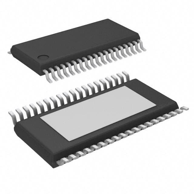
- Part No.:
- SCLT3-8BT8-TR
- Manufacturer:
- STMicroelectronics
- Category:
- Current Regulation/Management
- Package:
- 38-TFSOP (0.173", 4.40mm Width) Exposed Pad
- Datasheet:
-
 SCLT3-8BT8-TR.pdf
- Description:
- IC CURRENT LIMITING 38HTSSOP
- Quantity:
- Payment:

- Shipping:

Inventory:12,500
Please send an inquiry. Send us your inquiry, and we will respond immediately.
Product details
Overview
SCLT3-8BT8 from STMicroelectronics is an octal industrial digital input IC with current-sinking inputs compliant to IEC 61131-2 Types 1/2/3, 2.35 mA typical input current limit, integrated 20 µs–3 ms configurable digital filter, and SPI serial interface supporting both 8-bit and 16-bit modes with parity and diagnostics. It enables high-density PLC input modules with reduced heat dissipation and optocoupler count.
For engineers reviewing the SCLT3-8BT8 datasheet, SCLT3-8BT8 pinout, SCLT3-8BT8 application, or SCLT3-8BT8 equivalent, key selection criteria include IEC 61131-2 Type compliance, field-side LED driver capability, daisy-chain SPI support, reverse polarity tolerance (±35 V), and thermal robustness up to 105 °C ambient.
Technical Context
The device implements a two-stage digital glitch filter controlled by an external oscillator resistor (ROSC = 15 kΩ–1.2 MΩ), enabling programmable filtering times from 20 µs to 3 ms. Filter clock divider ratio (8 or 64) is selected via DVR pin connection to COMS or VDD.
Its SPI interface operates in CPOL = 0, CPHA = 0 mode with frame lengths configurable via SPM pin: 8-bit for raw input states only, or 16-bit including diagnostics (UVA, OTA), parity bits (PC1–PC4), and stop bits. Internal 5 V regulator powers logic section; field-side power (VC) supports up to 35 V with reverse polarity protection.
Key Specifications
| Parameter | Value and Actual Design Meaning |
|---|---|
| Input current limit | 2.35 mA typ at 24 V - ensures Type 1/3 compliance while minimizing power loss and thermal stress in dense I/O modules |
| Digital filter range | 20 µs to 3 ms - selectable via ROSC and DVR to suppress EMI/EMC noise without external RC networks |
| SPI frame mode | 8-bit or 16-bit with parity - 16-bit mode delivers diagnostics (UVA, OTA) and error detection for system-level reliability |
| Reverse polarity rating | ±35 V on VC pin - eliminates need for external reverse-blocking diodes in harsh factory environments |
| Ambient temperature | −40 °C to +105 °C - supports operation in uncooled control cabinets and motor drive enclosures |
| ESD immunity | ±15 kV air / ±8 kV contact (IEC 61000-4-2 Level 4) - protects against operator-induced static discharge at field terminals |
| Surge immunity | ±1 kV surge (IEC 61000-4-5, 42 Ω source) - withstands induced transients on long sensor wiring runs |
Pinout & Package
Package: HTSSOP-38 (9.7 mm × 4.4 mm × 1.1 mm, 0.65 mm pitch) - thermally enhanced for high-power industrial mounting with exposed thermal pad connected to COMP.
| Pin | Circuit Role | Design Meaning |
|---|---|---|
| INI (pins 8–11, 13–16) | Current-sinking digital input | Eight independent 24 V field inputs with programmable current limit; each sinks 2.35 mA typ into internal reference |
| LDI (pins 20–27) | LED driver output | Eight regulated current sources (2 mA typ) for energyless field-side status LEDs; no external driver needed |
| /CS, SCK, MOSI, MISO, /MISO | SPI interface signals | Standard CMOS-level SPI bus with optional inverted MISO for noise-immune isolation interfaces |
| VC, VCS, COMP | Field-side power domain | VC supplies 24 V field side; VCS senses VC voltage for UVA alarm; COMP is dedicated ground return for field power |
| SPM, DVR, OSC | Configuration & timing control | SPM selects 8/16-bit SPI mode; DVR sets filter clock divider (8/64); OSC sets filter time via external resistor |
Key Features
| Feature | Design Value |
|---|---|
| IEC 61131-2 Type 1/2/3 compliance | Configurable per-channel input thresholds (VTLH = 4.3 V, VTHL = 3.3 V, VTHYST = 1.0 V) with minimal external components |
| Daisy-chain SPI topology | Enables multi-device cascading using single isolation channel, reducing cost and board space in modular I/O systems |
| Integrated diagnostics | Real-time under-voltage alarm (/UVA, VCON = 17 V) and over-temperature alarm (/OTA, TON = 150 °C) reported in SPI frame |
| Energyless LED drivers | On-chip constant-current sources eliminate external LED driver ICs and reduce BOM count in visual status designs |
| Thermal derating support | Filter timing stability maintained across −40 °C to +105 °C; ILIM variation < ±0.3 mA over full junction temperature range |
Applications
| Programmable Logic Controller (PLC) Input Module | CNC Machine Tool I/O Subsystem |
|---|---|
|
Use Scenario: High-density 24 V DC discrete input card for rack-mounted PLCs handling 32+ channels per slot. IC Role / Device Role / Timing Role: Octal current-limiting serializer replacing eight optocouplers and associated biasing circuitry; provides EMC-robust digitization with 20 µs–3 ms filter tuning. Use Value: Reduces power dissipation by >60% vs. discrete optocoupler solutions and cuts PCB area by eliminating eight 6-pin SOIC footprints plus resistors. |
Use Scenario: Distributed I/O node on CNC controller backplane monitoring limit switches, tool sensors, and emergency stops. IC Role / Device Role / Timing Role: Field-side digital input conditioner with daisy-chain SPI output; integrates diagnostics for predictive maintenance of machine health. Use Value: Enables real-time reporting of /UVA and /OTA alarms over shared SPI bus, eliminating separate analog monitoring lines and ADC channels. |
| Motor Control Safety Interface | Industrial HMI Panel Input Expansion |
|
Use Scenario: Safety-rated input module interfacing emergency stop buttons and safety relays in servo drive cabinets. IC Role / Device Role / Timing Role: Current-limited, filtered, and serialized input front-end meeting SIL2 requirements via diagnostic coverage (parity, UVA, OTA). Use Value: Achieves functional safety compliance without external watchdog ICs or redundant microcontrollers-diagnostics embedded in SPI data stream. |
Use Scenario: Touchscreen HMI with auxiliary pushbutton and selector switch inputs mounted remotely on machine panels. IC Role / Device Role / Timing Role: Field-side LED driver + input serializer providing visual feedback (LDI pins) and state capture (INI pins) over same 24 V bus. Use Value: Eliminates separate LED driver IC and discrete input buffers, enabling compact 24 V-powered expansion boards with local status indication. |
Equivalent & Alternatives
The following parts are listed as comparable options for similar octal industrial digital input applications.
| Alternative Part | Technical Difference | Application Difference | Selection Advice |
|---|---|---|---|
| TI ISO1211 | Isolated 8-channel digital input with integrated galvanic isolation; no internal LED drivers; requires external 5 V supply for logic side | Used where reinforced isolation is mandatory (e.g., Class I equipment); lacks field-side LED drivers and daisy-chain SPI | Select when system-level isolation certification (UL 1577, VDE 0884-10) is required and LED indication is handled separately |
| Analog Devices AD7403 | Isolated sigma-delta modulator (not digital input); outputs bitstream, not serialized parallel states; no IEC 61131-2 compliance or current limiting | Targeted at analog sensor digitization (e.g., current sensing), not discrete 24 V signal acquisition | Not functionally equivalent-intended for precision analog-to-digital conversion, not industrial discrete input conditioning |
Compared with TI ISO1211 and AD7403, the SCLT3-8BT8 uniquely combines IEC 61131-2 compliance, integrated LED drivers, daisy-chain SPI, and field-side power regulation in a single HTSSOP-38 package-enabling lower-cost, higher-density, and self-contained digital input modules without external isolation or driver components.
Availability
SCLT3-8BT8 is available at Aetrix Electronics and suitable for programmable logic controller input modules, CNC machine tool I/O subsystems, and motor control safety interfaces requiring stable component supply, long-term industrial lifecycle support, and traceable sourcing.
Supply support for SCLT3-8BT8 includes scheduled delivery planning, volume procurement assistance, BOM continuity management, traceable sourcing, and lifecycle availability coordination for OEM customers, industrial embedded developers, connected-device designers, and electronics production programs.
Manufacturer
STMicroelectronics is a global semiconductor leader specializing in industrial, automotive, and power management solutions, with deep expertise in ruggedized analog and mixed-signal ICs for factory automation.
The SCLT3 series belongs to ST's industrial interface portfolio, designed specifically to replace optocoupler-based digital input circuits in PLCs and motion controllers-reducing power, size, and component count while maintaining IEC 61131-2 compliance and EMC robustness.
FAQ
What is the maximum field input voltage the SCLT3-8BT8 can withstand?
The SCLT3-8BT8 supports a continuous field-side supply voltage (VC) of 15–35 V DC, with absolute maximum rating of −35 V to +35 V. Its reverse polarity capability (±35 V) is achieved via internal protection architecture-no external diode is required when VC is connected directly to 24 V field wiring, even if polarity is accidentally reversed during installation or maintenance.
How does the digital filter configuration affect maximum input signal frequency?
Filter time (tFT) directly limits maximum input frequency: at minimum tFT = 20 µs, max frequency is ~20 kHz; at maximum tFT = 3 ms, max frequency drops to ~186 Hz. Table 8 in DS11042 shows precise relationships-e.g., ROSC = 51 kΩ + DVR = COMS yields tFT ≈ 18–210 µs and supports up to 30 kHz input transitions, suitable for fast encoder or pulse train inputs.
Can the SCLT3-8BT8 drive standard 24 V LEDs directly?
No-the LDI pins are constant-current sources rated for 2 mA typical with maximum output voltage of 2.7 V. They are designed exclusively for low-voltage indicator LEDs (e.g., red/green 2 V, 2 mA types). To drive 24 V LEDs, external transistor switches or dedicated LED drivers must be used; the LDI outputs are not 24 V tolerant and will be damaged if connected directly to 24 V supply rails.
Does the SCLT3-8BT8 require external components to meet IEC 61131-2 Type 2 compliance?
Yes-Type 2 requires ≥6 mA input current, exceeding the SCLT3-8BT8's 2.35 mA per channel. ST recommends paralleling two INI inputs per field signal with RREF = 9.1 kΩ and reduced input resistance (0.75 kΩ instead of 2.2 kΩ) to achieve ~7 mA total, as detailed in Section 3.6 of DS11042. This configuration is validated and documented-not a design inference.
SCLT3-8BT8-TR Specifications
- Product attributes
- Attribute value
- Manufacturer:
- STMicroelectronics
- Series:
- -
- Package/Case:
- 38-TFSOP (0.173", 4.40mm Width) Exposed Pad
- Packaging:
- Tape & Reel (TR)
- Product Status:
- Active
- Function:
- Current Limiting
- Sensing Method:
- High-Side
- Accuracy:
- -
- Voltage - Input:
- 15V ~ 35V
- Current - Output:
- 10mA
- Operating Temperature:
- -40°C ~ 105°C (TA)
- Grade:
- -
- Qualification:
- -
- Mounting Type:
- Surface Mount
- Supplier Device Package:
- 38-HTSSOP
SCLT3-8BT8-TR FAQ
1.How can I place an order for SCLT3-8BT8-TR through Aetrix?
Please submit a Request for Quotation (RFQ) for SCLT3-8BT8-TR on Aetrix. Our sales agent will provide a competitive quotation and guide you through the order confirmation once you accept the terms.
2.Are the price and stock information for SCLT3-8BT8-TR reliable?
The price and inventory of SCLT3-8BT8-TR are updated periodically and may fluctuate due to market conditions. Stock and pricing data are typically refreshed every 24 hours. Quotation validity for SCLT3-8BT8-TR is usually 5 days.
3.What payment methods are accepted for SCLT3-8BT8-TR?
We accept Wire Transfer, PayPal, Credit Card, Western Union, MoneyGram, and Escrow for SCLT3-8BT8-TR transactions.
Note: Certain payment methods may incur a processing fee.
4.How is shipping managed for SCLT3-8BT8-TR?
SCLT3-8BT8-TR orders can be shipped via leading logistics carriers, including DHL, UPS, FedEx, TNT, or Registered Mail.
Once your SCLT3-8BT8-TR order is processed, you will receive an email with the shipment details and tracking number.
Note: Tracking information may take up to 24 hours to appear. Express delivery typically takes 3–5 business days.
5.How can I obtain technical support or documentation for SCLT3-8BT8-TR?
For technical support, including SCLT3-8BT8-TR datasheets, pinout diagrams, or application guidance, please contact our engineering support team. They can provide detailed documentation and assistance for your SCLT3-8BT8-TR requirements.
6.How does Aetrix verify that SCLT3-8BT8-TR is sourced from the original manufacturer or authorized distributors?
All SCLT3-8BT8-TR products on Aetrix are procured from qualified distributors and authorized channels. Our dedicated quality assurance team conducts strict verification, including traceability checks and, if necessary, third-party testing. This ensures that SCLT3-8BT8-TR meets industry standards.
7.What is the process for return or replacement of SCLT3-8BT8-TR?
All SCLT3-8BT8-TR units undergo pre-shipment inspection (PSI). If there is an issue with SCLT3-8BT8-TR, returns or replacements are accepted under the following conditions:
1.Quantity discrepancies, incorrect items, or visible external defects (such as breakage or corrosion), acknowledged by Aetrix.
2.The issue is reported within 90 days of delivery.
3.The SCLT3-8BT8-TR part is unused and in its original packaging.
Return procedure for SCLT3-8BT8-TR:
1.Submit a request within 90 days.
2.Obtain a Return Material Authorization (RMA) from Aetrix.
SCLT3-8BT8-TR Tags
.jpg)
-
PSSI2021SAY,115
Nexperia USA Inc.

-
BCR401RE6327HTSA1
Infineon Technologies

-
INA199B2DCKR
Texas Instruments
-
INA199A1DCKR
Texas Instruments
-
INA199B1DCKR
Texas Instruments
-
NSI45015WT1G
onsemi
-
NSI45020T1G
onsemi
-
NSI45030AT1G
onsemi
-
NSI45025AT1G
onsemi
-
NSI45020AT1G
onsemi
-
NSI50010YT1G
onsemi
-
LM334Z/NOPB
Texas Instruments
Tech Hub

A practical engineering and sourcing framework covering lifecycle verification, lifetime-buy calculations, replacement qualification, supplier checks and counterfeit-risk controls.

TTL and CMOS logic families differ in thresholds, loading, output drive, power and timing. This engineering guide compares 74HC and 74HCT, calculates noise margins and checks 3.3 V/5 V compatibility.

A practical engineering guide to 3.3V and 5V logic compatibility, input thresholds, resistor dividers, translator ICs, MOSFET level shifting, I2C pull-ups, timing limits and power-sequencing risks.

The 74HC595 uses push-pull logic outputs, while the TPIC6B595 uses 50 V open-drain DMOS sinks for higher-power loads. This guide compares timing, current limits, 3.3 V interfacing, load wiring, thermal…

The 74HC595 converts serial data into eight stable parallel outputs. This guide covers pin functions, shift and storage timing, OE and MR behavior, drive-current limits, cascading, voltage compatibilit…

A technical comparison of level-sensitive latches and edge-triggered flip-flops, covering timing windows, setup and hold limits, master–slave operation, time borrowing, race-through, HDL inference and…

A D latch stores one bit while Enable controls when data can pass. This reference covers gate-level operation, truth tables, transparency, setup and hold timing, LE versus OE, common ICs and practical …

An SR latch stores one bit through cross-coupled feedback. This engineering reference covers NOR and NAND implementations, truth tables, forbidden-state recovery, gated operation, switch debouncing, fa…

Latch circuits retain one bit through feedback. This technical reference covers SR and D latches, truth tables, transparency, timing limits, latch-versus-flip-flop behavior, applications and common log…

An engineering guide to LED driver operation, constant-current and constant-voltage outputs, linear and switching topologies, dimming, IC selection, calculations, replacement compatibility, and fault c…


