
 My Inquiry
 My Account


Diodes Incorporated SD1A240GW
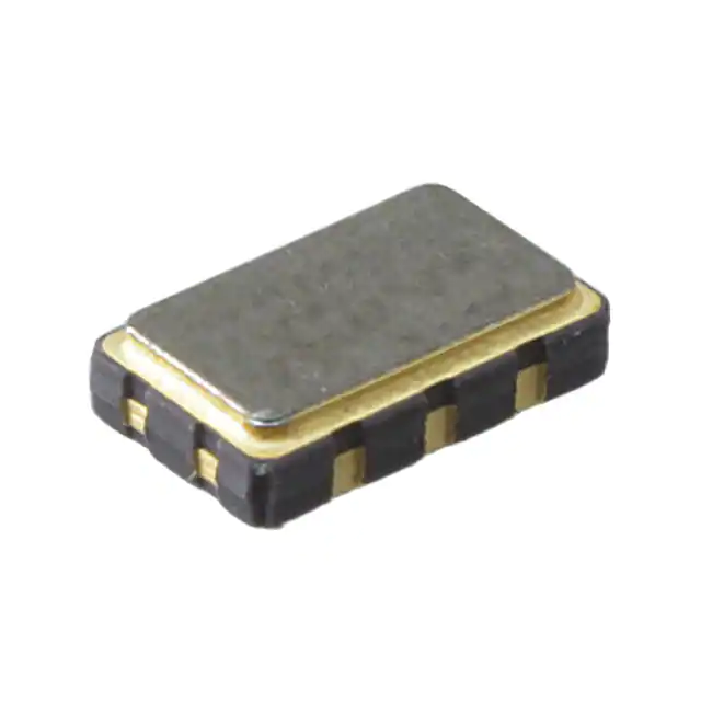
- Part No.:
- SD1A240GW
- Manufacturer:
- Diodes Incorporated
- Category:
- SCRs
- Package:
- -
- Datasheet:
-
 SD1A240GW.pdf
- Description:
- THYRISTOR DO-15 T&R 4K
- Quantity:
- Payment:

- Shipping:

Inventory:4,000
Please send an inquiry. Send us your inquiry, and we will respond immediately.
Product details
Overview
SD1A240GW from Lite-On is a bidirectional silicon-controlled switch (SIDAC) designed for AC line-triggered switching in phase-control and relaxation oscillator circuits. It features ±180 V repetitive off-state voltage (VDRM/VRRM), 1 A RMS on-state current, 216–234 V typical breakover voltage (VBO), <65 mA dynamic holding current (IH), and DO-15 package. Used in solid-state relays and lamp dimmers requiring precise high-voltage turn-on.
For engineers reviewing the SD1A240GW datasheet, SD1A240GW pinout, SD1A240GW application, or SD1A240GW equivalent, key selection criteria include verified VBO tolerance (216–234 V), di/dt rating (80 A/μs), thermal resistance (18 °C/W), compact DO-15 footprint, and UL recognition (E219635).
Technical Context
The SD1A240GW operates as a two-terminal, bidirectional trigger device without gate control - conduction initiates when applied voltage exceeds its symmetric breakover threshold (VBO = 216–234 V). It sustains conduction until current falls below dynamic holding current (IH ≤ 65 mA) under 50–60 Hz sine wave conditions.
Its internal structure enables symmetrical forward/reverse blocking (±180 V), low leakage (<5 μA IDRM/IRRM), and robust surge capability (ITSM = ±20 A, 60 Hz one-cycle). Thermal performance is defined by RthJL = 18 °C/W with lead length 3/8″, supporting reliable operation from –40 to +125 °C junction temperature.
Key Specifications
| Parameter | Value and Actual Design Meaning |
|---|---|
| VDRM / VRRM | ±180 V - Specifies maximum repeatable AC line voltage the device blocks in both directions before triggering. |
| VBO | 216–234 V - Confirmed symmetric DC breakover range at IBO = 0.5 mA; defines precise turn-on threshold for timing circuits. |
| IH (dynamic) | ≤65 mA - Maximum current below which conduction ceases; ensures clean turn-off in RL-loaded 50–60 Hz applications. |
| di/dt (critical) | 80 A/μs - Minimum rate of current rise required to sustain latching after breakover; prevents false triggering. |
| RthJL | 18 °C/W - Junction-to-lead thermal resistance with 3/8″ lead length; enables power derating calculations for PCB layout. |
| IT(RMS) | ±1 A - Continuous RMS current handling capacity under specified thermal conditions; sets maximum load drive capability. |
| VTM | ≤3 V - Peak on-state voltage at 1 A pulse; determines conduction loss and self-heating during active state. |
Pinout & Package
SD1A240GW uses the axial-leaded DO-15 package (A = 25.4 mm, B = 3.60 mm, C = 2.60 mm, D = 0.71 mm, lead diameter = 0.86 mm). Two terminals only - no polarity or gate distinction.
| Pin/Terminal | Circuit Role | Design Meaning |
|---|---|---|
| Anode/Cathode (A/K) | Bidirectional main terminal | Interchangeable terminals; voltage applied across either polarity triggers conduction when |V| ≥ VBO. |
Key Features
| Feature | Design Value |
|---|---|
| Symmetric bidirectional switching | Identical VDRM/VRRM (±180 V) and VBO (216–234 V) enable AC line sensing without rectification or polarity awareness. |
| Tight VBO tolerance | ±6 V window (216–234 V) ensures predictable, repeatable turn-on timing in relaxation oscillators and phase controllers. |
| Low dynamic holding current | IH ≤ 65 mA guarantees reliable turn-off at low-current zero-crossings in 50–60 Hz AC loads. |
| UL-recognized construction | File # E219635 confirms compliance with UL 1557 for use in safety-critical AC-powered equipment. |
Applications
| Lamp Dimming Circuit | AC Motor Speed Control |
|---|---|
Use Scenario: Phase-angle controlled dimming of incandescent or halogen lamps on 120/230 VAC mains. IC Role / Device Role / Timing Role: Bidirectional trigger element that fires at precise voltage threshold to control SCR/TRIAC gate timing. Use Value: VBO tolerance (216–234 V) enables stable dimming angle across line voltage variation and temperature drift. | Use Scenario: Variable-speed control of universal or shaded-pole AC motors in fans, pumps, and appliances. IC Role / Device Role / Timing Role: High-voltage trigger for TRIAC-based phase control, replacing RC timing networks with improved repeatability. Use Value: Symmetric ±180 V blocking and 80 A/μs di/dt rating ensure robust triggering even under motor inrush and back-EMF transients. |
| Overvoltage Protection Clamp | Relaxation Oscillator Timer |
Use Scenario: Crowbar-style overvoltage protection in DC power supplies or AC line monitors. IC Role / Device Role / Timing Role: Voltage-triggered shunt device that latches on when input exceeds safe threshold, diverting fault current. Use Value: Precise 216–234 V VBO range allows accurate clamping setpoint without external reference or feedback. | Use Scenario: Low-component-count timing generator for LED flashers, buzzer drivers, or reset pulses. IC Role / Device Role / Timing Role: Core relaxation oscillator element charging capacitor until VBO is reached, then discharging through load. Use Value: Tight VBO tolerance and low IH (≤65 mA) yield stable, temperature-compensated oscillation frequency without trimming. |
Equivalent & Alternatives
The following parts are listed as comparable options for similar SIDAC applications.
| Alternative Part | Technical Difference | Application Difference | Selection Advice |
|---|---|---|---|
| NTE6408 | VBO = 220–240 V; IT(RMS) = 1 A; same DO-15 package; higher max VBO upper limit (+6 V). | Marginally wider VBO spread reduces timing precision in oscillator designs. | Acceptable where ±10 V VBO tolerance is acceptable and UL recognition is not required. |
| K2403S | VBO = 230–250 V; IT(RMS) = 1.25 A; TO-92 package; no UL file listed. | Larger VBO range delays turn-on, requiring circuit re-timing; TO-92 limits power dissipation. | Preferred only if higher current rating is needed and board space permits larger footprint. |
Compared with NTE6408 and K2403S, SD1A240GW offers the narrowest VBO range (216–234 V), UL recognition, and optimal thermal resistance (18 °C/W) for compact DO-15 layouts - making it superior for precision timing and safety-compliant AC control.
Availability
SD1A240GW is available at Aetrix Electronics and suitable for lamp dimming, AC motor control, overvoltage protection, and relaxation oscillator timing requiring stable component supply and consistent VBO performance.
Supply support for SD1A240GW includes scheduled delivery planning, volume procurement assistance, BOM continuity management, traceable sourcing, and lifecycle availability coordination for OEM customers, industrial embedded developers, connected-device designers, and electronics production programs.
Manufacturer
Lite-On Semiconductor (LSC) is a Taiwan-based semiconductor manufacturer specializing in optoelectronics, discrete power devices, and analog ICs, with global manufacturing and quality certifications.
The SD1A240GW belongs to Lite-On's SIDAC product line, engineered for high-reliability, zero-crossing–independent AC switching in cost-sensitive industrial and consumer controls.
FAQ
Is SD1A240GW a TRIAC or a SIDAC?
SD1A240GW is a SIDAC - a two-terminal, bidirectional trigger device without gate control. Unlike a TRIAC, it has no gate terminal and turns on solely when voltage across its terminals exceeds VBO (216–234 V). It conducts until current drops below IH (≤65 mA), then resets automatically.
Can SD1A240GW replace a DIAC in a light dimmer circuit?
Yes - SD1A240GW can directly replace standard DIACs (e.g., DB3) in TRIAC-based dimmers. Its higher VBO (216–234 V vs. ~32 V for DIACs) shifts firing angle later in the AC cycle, enabling deeper dimming range and reduced EMI due to slower dv/dt onset.
What is the maximum allowable lead temperature during soldering?
The maximum lead solder temperature is 260 °C for up to 10 seconds, measured at a point 1/16″ from the case body. Exceeding this risks internal bond wire damage or passivation layer degradation, compromising VBO stability and long-term reliability.
Does SD1A240GW require a heat sink in 1 A RMS operation?
No - at 1 A RMS with 3/8″ lead length and ambient ≤40 °C, junction temperature remains within –40 to +125 °C limits using RthJL = 18 °C/W. Heat sinking is unnecessary unless operating above 60 °C ambient or with >50% duty-cycle pulsed loads.
SD1A240GW Specifications
- Product attributes
- Attribute value
- Manufacturer:
- Diodes Incorporated
- Series:
- -
- Package/Case:
- -
- Packaging:
- Tape & Reel (TR)
- Product Status:
- Active
- Voltage - Off State:
- -
- Voltage - Gate Trigger (Vgt) (Max):
- -
- Current - Gate Trigger (Igt) (Max):
- -
- Voltage - On State (Vtm) (Max):
- -
- Current - On State (It (AV)) (Max):
- -
- Current - On State (It (RMS)) (Max):
- -
- Current - Hold (Ih) (Max):
- -
- Current - Off State (Max):
- -
- Current - Non Rep. Surge 50, 60Hz (Itsm):
- -
- SCR Type:
- -
- Operating Temperature:
- -
- Grade:
- -
- Qualification:
- -
- Mounting Type:
- -
- Supplier Device Package:
- -
SD1A240GW FAQ
1.How can I place an order for SD1A240GW through Aetrix?
Please submit a Request for Quotation (RFQ) for SD1A240GW on Aetrix. Our sales agent will provide a competitive quotation and guide you through the order confirmation once you accept the terms.
2.Are the price and stock information for SD1A240GW reliable?
The price and inventory of SD1A240GW are updated periodically and may fluctuate due to market conditions. Stock and pricing data are typically refreshed every 24 hours. Quotation validity for SD1A240GW is usually 5 days.
3.What payment methods are accepted for SD1A240GW?
We accept Wire Transfer, PayPal, Credit Card, Western Union, MoneyGram, and Escrow for SD1A240GW transactions.
Note: Certain payment methods may incur a processing fee.
4.How is shipping managed for SD1A240GW?
SD1A240GW orders can be shipped via leading logistics carriers, including DHL, UPS, FedEx, TNT, or Registered Mail.
Once your SD1A240GW order is processed, you will receive an email with the shipment details and tracking number.
Note: Tracking information may take up to 24 hours to appear. Express delivery typically takes 3–5 business days.
5.How can I obtain technical support or documentation for SD1A240GW?
For technical support, including SD1A240GW datasheets, pinout diagrams, or application guidance, please contact our engineering support team. They can provide detailed documentation and assistance for your SD1A240GW requirements.
6.How does Aetrix verify that SD1A240GW is sourced from the original manufacturer or authorized distributors?
All SD1A240GW products on Aetrix are procured from qualified distributors and authorized channels. Our dedicated quality assurance team conducts strict verification, including traceability checks and, if necessary, third-party testing. This ensures that SD1A240GW meets industry standards.
7.What is the process for return or replacement of SD1A240GW?
All SD1A240GW units undergo pre-shipment inspection (PSI). If there is an issue with SD1A240GW, returns or replacements are accepted under the following conditions:
1.Quantity discrepancies, incorrect items, or visible external defects (such as breakage or corrosion), acknowledged by Aetrix.
2.The issue is reported within 90 days of delivery.
3.The SD1A240GW part is unused and in its original packaging.
Return procedure for SD1A240GW:
1.Submit a request within 90 days.
2.Obtain a Return Material Authorization (RMA) from Aetrix.
SD1A240GW Tags
-
MCR12DSNT4G
Littelfuse Inc.
-
2N6404G
Littelfuse Inc.
-
S4015LTP
Littelfuse Inc.
-
VS-25TTS12HM3
Vishay General Semiconductor - Diodes Division
-
S4020LTP
Littelfuse Inc.
-
MCR12MG
Littelfuse Inc.
-
MCR69-3G
Littelfuse Inc.
-
S8025LTP
Littelfuse Inc.
-
CMA30E1600PN
IXYS
-
S8016RATP
Littelfuse Inc.
-
TXN625RG
STMicroelectronics
.jpg)
-
SK055RTP
Littelfuse Inc.
Tech Hub

An engineering guide to LED driver operation, constant-current and constant-voltage outputs, linear and switching topologies, dimming, IC selection, calculations, replacement compatibility, and fault c…

Operational amplifier guide covering op amp basics, feedback, ideal vs real op amps, common configurations, buffer circuits, offset, bias current, gain-bandwidth, slew rate, rail-to-rail limits and sel…

Jumper cables guide covering safe connection order, red and black clamp placement, final ground connection, cable gauge, length, clamp quality, copper vs CCA cables, jump starter comparison and battery…

LDO regulator guide covering low dropout voltage, power dissipation, thermal design, PSRR, output noise, capacitor stability, adjustable LDO circuits, LDO vs buck converter and datasheet selection chec…

Conditional Access Module guide covering CAM meaning, CI/CI+ interface, smart card authorization, DVB security workflow, TV and set-top box compatibility, internal electronics, ESD protection, connecto…

Guide to electronic component obsolescence covering EOL risk, PCN/PDN notices, last-time buy planning, replacement options, form-fit-function validation, counterfeit risk and BOM lifecycle management.

18650 battery guide covering lithium-ion cell basics, 3.6V/3.7V voltage, 4.2V charging, mAh and Wh capacity, protected cells, chargers, BMS, series-parallel packs, holders, welding and sourcing checks.…

Hall effect sensor guide covering working principle, linear and digital sensors, Arduino circuits, current sensing, speed detection, automotive applications, A3144 examples, signal filtering and datash…

Product Change Notification guide for electronic components, covering PCN meaning, PCN vs PDN/EOL, common change types, risk levels, form-fit-function review, engineering validation, BOM control, LTB/L…

A practical guide to blend door actuators, covering HVAC function, symptoms, location, AC and heater issues, reset and calibration, replacement cost, electrical diagnosis, compatibility checks, and rep…


