
 My Inquiry
 My Account


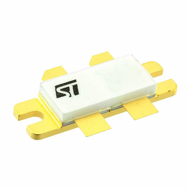
STMicroelectronics SD2932W
- Part No.:
- SD2932W
- Manufacturer:
- STMicroelectronics
- Category:
- Single FETs, MOSFETs
- Package:
- M244
- Datasheet:
-
 SD2932W.pdf
- Description:
- RF MOSFET 50V M244
- Quantity:
- Payment:

- Shipping:

Inventory:52
Please send an inquiry. Send us your inquiry, and we will respond immediately.
Product details
Overview
SD2932W from STMicroelectronics is a gold-metallized N-channel RF power MOSFET in M244 package, rated for 125 VBRDSS, 40 A continuous drain current, and 500 W power dissipation, delivering ≥300 W output with 15 dB gain at 175 MHz in common-source push-pull amplifier configurations for HF/VHF/UHF broadcast and industrial RF heating systems.
For engineers reviewing the SD2932W datasheet, SD2932W pinout, SD2932W application, or SD2932W equivalent, key selection criteria include junction-to-case thermal resistance (0.35 °C/W), gate threshold voltage range (1.5–4 V), broadband performance across 88–230 MHz, load mismatch tolerance up to 5:1 VSWR, and compatibility with 50 V DC large-signal RF power stages.
Technical Context
The SD2932W employs a dual-gate, balanced structure optimized for push-pull operation, with matched gate-source voltage tracking (ΔVGS ≤ 200 mV) ensuring symmetrical drive in Class AB/B RF amplifiers. Its low RthJC (0.35 °C/W) enables high-power operation without forced-air cooling in compact heatsink designs.
Designed for fixed-frequency and broadband RF power amplification, it supports stable operation under wide impedance variations - demonstrated by 5:1 VSWR tolerance at full 300 W output and consistent gain flatness (15–16 dB) from 175–230 MHz with >50% drain efficiency.
Key Specifications
| Parameter | Value and Actual Design Meaning |
|---|---|
| VBRDSS | 125 V - Withstands 50 V DC supply with 2.5× safety margin for transient spikes in RF amplifier rails. |
| POUT @ 175 MHz | ≥300 W - Delivers full legal-limit broadcast power in FM transmitters and industrial plasma generators. |
| GPS @ 175 MHz | 15–16 dB - Enables single-stage amplification from driver-level input (≈10 W) to final output (≥300 W). |
| ηD @ 300 W | 50–60 % - Minimizes heat generation and power supply burden in continuous-duty RF heating applications. |
| RthJC | 0.35 °C/W - Allows direct mounting to aluminum heatsinks with <10 °C temperature rise at 500 W dissipation. |
| ZIN @ 175 MHz | 0.92 − j0.14 Ω - Matches standard 50 Ω gate drive networks with minimal external tuning components. |
| CISS / COSS | 480 pF / 190 pF - Supports stable broadband matching with predictable input/output capacitance roll-off vs. frequency. |
Pinout & Package
The SD2932W is housed in the M244 hermetically sealed, flanged, 4-lead balanced package (0.400″ × 0.860″), designed for high-frequency RF grounding and thermal management via baseplate mounting. Leads are arranged symmetrically for push-pull layout with isolated gate and drain terminals on each side.
| Pin/Terminal | Circuit Role | Design Meaning |
|---|---|---|
| Lead 1 (Left Drain) | Drain terminal (Side 1) | High-current RF output node; electrically isolated from Lead 4; requires low-inductance connection to output matching network. |
| Lead 2 (Left Gate) | Gate terminal (Side 1) | Signal input for one half of push-pull pair; matched to Lead 3 for balanced drive; ΔVGS ≤ 200 mV ensures symmetry. |
| Lead 3 (Right Gate) | Gate terminal (Side 2) | Signal input for second half of push-pull pair; internally matched to Lead 2; enables differential gate drive without external balun. |
| Lead 4 (Right Drain) | Drain terminal (Side 2) | Second high-current RF output node; isolated from Lead 1; used with complementary phase signal for vector sum output. |
Key Features
| Feature | Design Value |
|---|---|
| Gold metallization | Ensures long-term bond-wire reliability and low contact resistance at RF frequencies up to 250 MHz. |
| Common-source push-pull configuration | Eliminates need for external hybrid couplers or baluns; simplifies PCB layout and improves amplitude/phase balance. |
| Matched gate-source thresholds (ΔVGS) | ≤200 mV tolerance enables precise current sharing between halves without individual bias trimming. |
| Hermetic M244 package | Provides moisture-resistant sealing and stable electrical performance over -65 to +150 °C storage range. |
| 5:1 VSWR load tolerance | Guarantees safe operation into mismatched antennas or plasma loads without device failure or gain collapse. |
Applications
| Broadcast FM Transmitter Final Stage | Industrial RF Plasma Generator |
|---|---|
Use Scenario: 100 W driver stage feeding SD2932W in push-pull configuration to deliver 300 W into 50 Ω antenna system at 98.5 MHz. IC Role / Device Role / Timing Role: Final RF power amplification stage operating in Class AB with fixed 50 V DC supply and broadband matching. Use Value: Achieves 55% drain efficiency and 15.5 dB power gain without harmonic filtering, reducing BOM count and thermal footprint. | Use Scenario: Paired SD2932W devices driving parallel resonant tank at 13.56 MHz for semiconductor wafer etching chamber excitation. IC Role / Device Role / Timing Role: High-reliability RF power switch delivering pulsed 300 W output synchronized to process timing controller. Use Value: Gold metallization and 0.35 °C/W RthJC sustain >10,000 hours MTBF under 85 °C case temperature cycling. |
| UHF TV Transmitter Output Module | Amateur Radio Linear Amplifier |
Use Scenario: Two SD2932W units in push-pull configuration amplifying 175 MHz carrier to 300 W for digital TV transmission (ATSC 3.0). IC Role / Device Role / Timing Role: Fixed-frequency, high-linearity RF power stage with 5:1 VSWR tolerance for antenna impedance variation. Use Value: Maintains <−30 dBc 2nd/3rd harmonics per Figure 29–30, meeting FCC spectral mask requirements without external filters. | Use Scenario: Homebrew 1.8–54 MHz linear amplifier using SD2932W with broadband matching network covering HF through UHF bands. IC Role / Device Role / Timing Role: General-purpose RF power transistor operated in Class AB with adjustable quiescent current (IDQ = 500 mA). Use Value: Delivers ≥14 dB gain across 88–230 MHz (Fig. 20) and supports manual tuning via front-panel potentiometers (R9/R10 per Fig. 16). |
Equivalent & Alternatives
The following parts are listed as comparable options for similar RF power MOSFET applications.
| Alternative Part | Technical Difference | Application Difference | Selection Advice |
|---|---|---|---|
| MRF1K50N | Higher VBRDSS (150 V), lower RthJC (0.25 °C/W), but requires external gate balancing network. | Optimized for 1.3–1.6 GHz L/S-band radar; less suitable below 100 MHz due to gain roll-off. | Select when operating above 200 MHz or requiring >1 kW peak power with active thermal monitoring. |
| BLF188XR | Same M244 package, higher POUT (400 W @ 175 MHz), but narrower bandwidth (130–230 MHz only). | Targeted at DVB-T2 broadcast; lacks 88–108 MHz data and harmonic suppression specs below 130 MHz. | Select for new 175–230 MHz broadcast designs where 300 W headroom is insufficient and board space allows tighter layout. |
Compared with MRF1K50N and BLF188XR, the SD2932W offers broader low-end coverage (down to 88 MHz), verified 5:1 VSWR robustness, and integrated gate matching - making it uniquely suited for cost-sensitive, multi-band HF/VHF/UHF transmitters where design simplicity and field reliability are prioritized over peak power density.
Availability
SD2932W is available at Aetrix Electronics and suitable for broadcast FM transmitters, industrial RF plasma generators, and amateur radio linear amplifiers requiring stable component supply with traceable lot control and long-lifecycle support.
Supply support for SD2932W includes scheduled delivery planning, volume procurement assistance, BOM continuity management, traceable sourcing, and lifecycle availability coordination for OEM customers, industrial embedded developers, connected-device designers, and electronics production programs.
Manufacturer
STMicroelectronics is a global semiconductor leader headquartered in Geneva, Switzerland, designing and manufacturing analog, power, microcontroller, and RF solutions for industrial, automotive, and communications markets.
The SD2932W belongs to ST's high-power RF MOSFET product line, engineered specifically for ruggedized HF/VHF/UHF amplifier stages where thermal stability, broadband gain flatness, and load mismatch resilience are critical system requirements.
FAQ
What is the maximum recommended gate-source voltage for continuous operation?
The SD2932W has an absolute maximum VGS rating of ±40 V, but for reliable long-term operation, ST specifies a gate drive range of 0 to +10 V in typical Class AB push-pull configurations. Exceeding +10 V increases risk of gate oxide stress and threshold shift, especially at elevated case temperatures above 80 °C.
Can SD2932W be used in single-ended mode instead of push-pull?
Yes, but with significant derating: maximum POUT drops to 150 W at 175 MHz, gain falls to ~12 dB, and efficiency decreases to ~40%. The internal dual-gate structure remains functional, but thermal imbalance and harmonic distortion increase without complementary drive, requiring careful heatsinking and output filtering.
Is the M244 package RoHS-compliant and lead-free?
Yes - the SD2932W is manufactured in ST's ECOPACK®-compliant M244 package, meeting RoHS Directive 2011/65/EU and JEDEC J-STD-020 moisture sensitivity level (MSL) 3. Full compliance documentation, including Pb-free plating and halogen-free molding compound, is available in ST's ECOPACK® database at www.st.com.
What is the typical gate charge (QG) value, and how does it affect switching speed?
While QG is not explicitly published, derived values from CISS (480 pF), COSS (190 pF), and CRSS (18 pF) indicate total effective gate charge ≈ 120 nC at VGS = 10 V. This supports fast RF switching up to 250 MHz but requires low-impedance gate drivers (<5 Ω source impedance) to minimize switching losses in pulsed applications.
SD2932W Specifications
- Product attributes
- Attribute value
- Manufacturer:
- STMicroelectronics
- Series:
- -
- Package/Case:
- M244
- Packaging:
- Tube
- Product Status:
- Active
- Technology:
- MOSFET (Metal Oxide)
- Configuration:
- N-Channel
- Frequency:
- 175MHz
- Gain:
- 16dB
- Voltage - Test:
- 50 V
- Current Rating (Amps):
- 40A
- Noise Figure:
- -
- Current - Test:
- 500 mA
- Power - Output:
- 300W
- Voltage - Rated:
- 125 V
- Grade:
- -
- Qualification:
- -
- Mounting Type:
- -
- Supplier Device Package:
- M244
SD2932W FAQ
1.How can I place an order for SD2932W through Aetrix?
Please submit a Request for Quotation (RFQ) for SD2932W on Aetrix. Our sales agent will provide a competitive quotation and guide you through the order confirmation once you accept the terms.
2.Are the price and stock information for SD2932W reliable?
The price and inventory of SD2932W are updated periodically and may fluctuate due to market conditions. Stock and pricing data are typically refreshed every 24 hours. Quotation validity for SD2932W is usually 5 days.
3.What payment methods are accepted for SD2932W?
We accept Wire Transfer, PayPal, Credit Card, Western Union, MoneyGram, and Escrow for SD2932W transactions.
Note: Certain payment methods may incur a processing fee.
4.How is shipping managed for SD2932W?
SD2932W orders can be shipped via leading logistics carriers, including DHL, UPS, FedEx, TNT, or Registered Mail.
Once your SD2932W order is processed, you will receive an email with the shipment details and tracking number.
Note: Tracking information may take up to 24 hours to appear. Express delivery typically takes 3–5 business days.
5.How can I obtain technical support or documentation for SD2932W?
For technical support, including SD2932W datasheets, pinout diagrams, or application guidance, please contact our engineering support team. They can provide detailed documentation and assistance for your SD2932W requirements.
6.How does Aetrix verify that SD2932W is sourced from the original manufacturer or authorized distributors?
All SD2932W products on Aetrix are procured from qualified distributors and authorized channels. Our dedicated quality assurance team conducts strict verification, including traceability checks and, if necessary, third-party testing. This ensures that SD2932W meets industry standards.
7.What is the process for return or replacement of SD2932W?
All SD2932W units undergo pre-shipment inspection (PSI). If there is an issue with SD2932W, returns or replacements are accepted under the following conditions:
1.Quantity discrepancies, incorrect items, or visible external defects (such as breakage or corrosion), acknowledged by Aetrix.
2.The issue is reported within 90 days of delivery.
3.The SD2932W part is unused and in its original packaging.
Return procedure for SD2932W:
1.Submit a request within 90 days.
2.Obtain a Return Material Authorization (RMA) from Aetrix.
SD2932W Tags
-
3SK294(TE85L,F)
Toshiba Semiconductor and Storage

-
SAV-551+
Mini-Circuits

-
TAV2-501+
Mini-Circuits
-
CE3514M4-C2
CEL
-
AFT05MS004NT1
NXP USA Inc.
-
SAV-541+
Mini-Circuits
-
CE3512K2-C1
CEL
-
AFM907NT1
NXP USA Inc.
-
SKY65050-372LF
Skyworks Solutions Inc.
-
CE3520K3-C1
CEL
-
AFT09MS007NT1
NXP USA Inc.
-
AFT09MS015NT1
NXP USA Inc.
Tech Hub

Jumper cables guide covering safe connection order, red and black clamp placement, final ground connection, cable gauge, length, clamp quality, copper vs CCA cables, jump starter comparison and battery…

LDO regulator guide covering low dropout voltage, power dissipation, thermal design, PSRR, output noise, capacitor stability, adjustable LDO circuits, LDO vs buck converter and datasheet selection chec…

Conditional Access Module guide covering CAM meaning, CI/CI+ interface, smart card authorization, DVB security workflow, TV and set-top box compatibility, internal electronics, ESD protection, connecto…

Guide to electronic component obsolescence covering EOL risk, PCN/PDN notices, last-time buy planning, replacement options, form-fit-function validation, counterfeit risk and BOM lifecycle management.

18650 battery guide covering lithium-ion cell basics, 3.6V/3.7V voltage, 4.2V charging, mAh and Wh capacity, protected cells, chargers, BMS, series-parallel packs, holders, welding and sourcing checks.…

Hall effect sensor guide covering working principle, linear and digital sensors, Arduino circuits, current sensing, speed detection, automotive applications, A3144 examples, signal filtering and datash…

Product Change Notification guide for electronic components, covering PCN meaning, PCN vs PDN/EOL, common change types, risk levels, form-fit-function review, engineering validation, BOM control, LTB/L…

A practical guide to blend door actuators, covering HVAC function, symptoms, location, AC and heater issues, reset and calibration, replacement cost, electrical diagnosis, compatibility checks, and rep…

Engineering guide to Raspberry Pi alternatives, covering chip-level differences, Orange Pi, ROCK, Jetson, Banana Pi, NanoPi, Compute Module, Pico, GPIO, camera, HAT compatibility, and replacement risks…

Engineering guide to dynamic load response testing for high-current buck converters, covering load step setup, slew rate, Vcore undershoot, overshoot, recovery time, probe location, output capacitors a…


