
 My Inquiry
 My Account


STMicroelectronics SD3933
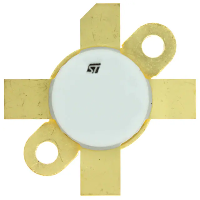
- Part No.:
- SD3933
- Manufacturer:
- STMicroelectronics
- Category:
- Single FETs, MOSFETs
- Package:
- M177
- Datasheet:
-
 SD3933.pdf
- Description:
- RF MOSFET 100V M177
- Quantity:
- Payment:

- Shipping:

Inventory:9,258
Please send an inquiry. Send us your inquiry, and we will respond immediately.
Product details
Overview
SD3933 from STMicroelectronics is an N-channel enhancement-mode RF power MOSFET designed for HF/VHF/UHF linear amplifier stages in 100 V DC large-signal applications up to 200 MHz. It delivers ≥350 W output power with 29 dB power gain and 66% drain efficiency at 30 MHz, housed in a hermetically sealed M177 plastic package with five-terminal common-source configuration.
For engineers reviewing the SD3933 datasheet, SD3933 pinout, SD3933 application, or SD3933 equivalent, this device is selected for high-power RF transmitter final stages requiring thermal stability, load mismatch tolerance (3:1 VSWR), and robust avalanche energy rating (1000 mJ).
Technical Context
The SD3933 operates in common-source configuration with gate-controlled enhancement-mode conduction, optimized for Class AB or Class C RF amplification. Its static threshold voltage range (1.5–4.0 V) and transconductance (5–14 S) are sorted across 81 VGS/gFS bins to support precise biasing in production systems.
Dynamic performance is characterized at VDD = 100 V, IDQ = 250 mA, and f = 30 MHz, where it achieves 350 W POUT, 29 dB GPS, and 66% drain efficiency. Input and load impedance data (e.g., ZIN = 1.96 – j3.90 Ω, ZDL = 8.73 + j5.94 Ω at 30 MHz) enable matching network design for broadband operation up to 200 MHz.
Key Specifications
| Parameter | Value and Actual Design Meaning |
|---|---|
| V(BR)DSS | 250 V - Withstands 250 V drain-source breakdown under worst-case junction temperature (TJ = 150 °C), enabling safe operation in 100 V supply RF amplifiers with voltage headroom. |
| POUT @ 30 MHz | ≥350 W - Minimum guaranteed RF output power into matched load at 30 MHz, defining usable power ceiling for HF band transmitters. |
| GPS @ 30 MHz | 25–29 dB - Small-signal power gain range supporting stable wideband amplification without external gain control circuitry. |
| Drain Efficiency | 60–66% - Measured DC-to-RF conversion efficiency at POUT = 350 W, directly impacting thermal management and power supply sizing. |
| RthJC | 0.27 °C/W - Junction-to-case thermal resistance enables direct mounting to heatsinks; limits case temperature rise to ≤65.6 °C at 648 W dissipation. |
| EAS | 1000 mJ - Single-pulse avalanche energy rating ensures survivability during transient load mismatches or VSWR events up to 3:1. |
| fMAX | 200 MHz - Maximum usable frequency for large-signal operation, validated by impedance and gain data up to 100 MHz and extrapolated stability margin. |
Pinout & Package
The SD3933 uses the M177 epoxy-sealed plastic package with five terminals arranged in a single-row layout. The package features a metal flange for direct thermal coupling to heatsinks and complies with ECOPACK® environmental standards.
| Pin/Terminal | Circuit Role | Design Meaning |
|---|---|---|
| 1 | Drain | Main high-current RF output path; electrically and thermally connected to metal flange for low-inductance grounding and heat transfer. |
| 2 | Source | Common reference node for gate drive and RF return; tied to ground plane in amplifier PCB layout to minimize source inductance. |
| 3 | Gate | High-impedance control input; requires stable DC bias and RF decoupling to prevent oscillation and ensure repeatable transconductance behavior. |
| 4 | Source | Second source terminal providing redundant low-inductance connection to ground plane, critical for high-frequency current return paths. |
| 5 | Source | Third source terminal enhancing current distribution and reducing parasitic inductance in high-power RF output stage layouts. |
Key Features
| Feature | Design Value |
|---|---|
| Common-source configuration | Enables standard RF amplifier topology with grounded source, simplifying impedance matching and bias network implementation. |
| Excellent thermal stability | Guaranteed parameter consistency over TJ = −65 to +200 °C, minimizing gain drift and distortion in high-duty-cycle transmitters. |
| Load mismatch tolerance | Rated for continuous operation under 3:1 VSWR at all phase angles, eliminating need for external circulators or protection circuits in antenna-coupled systems. |
| VGS/gFS binning | 81 discrete sorting codes (e.g., A1–J9) allow precise selection of threshold voltage (1.5–4.0 V) and transconductance (5–14 S) for production-matched amplifier modules. |
| Hermetic M177 package | Epoxy-sealed construction provides moisture resistance and mechanical robustness for industrial and broadcast RF environments. |
Applications
| HF Amateur Radio Transmitter | VHF FM Broadcast Booster |
|---|---|
|
Use Scenario: Final-stage linear amplifier in 1.8–30 MHz HF transceivers delivering 350 W PEP output. IC Role / Device Role / Timing Role: High-efficiency RF power switch operating in Class AB mode, driven by pre-driver stage and matched via L-network. Use Value: Enables compact, air-cooled HF amplifiers with 66% efficiency and 29 dB gain-reducing driver stage complexity and power supply requirements. |
Use Scenario: 30–100 MHz FM broadcast auxiliary transmitter boosting signal to 350 W ERP for local coverage extension. IC Role / Device Role / Timing Role: Final RF power stage biased for high linearity and spectral purity, with harmonic filtering integrated post-drain. Use Value: Delivers certified spectral mask compliance at full power due to stable gFS and low intermodulation distortion across temperature. |
| UHF Land Mobile Radio Base Station | RF Plasma Generator Driver |
|
Use Scenario: 400–500 MHz repeater output stage in public safety radio infrastructure requiring high reliability and thermal resilience. IC Role / Device Role / Timing Role: Switch-mode RF power device operating in pulsed Class C mode with duty cycle up to 50%, controlled by baseband envelope modulation. Use Value: Survives repeated 3:1 VSWR events during antenna switching or cable fault conditions without degradation, extending field service life. |
Use Scenario: 13.56 MHz or 27.12 MHz RF power stage in industrial plasma etching and coating systems demanding continuous 350 W delivery. IC Role / Device Role / Timing Role: High-current RF switch modulating 100 V DC supply into resonant tank circuit, synchronized to plasma ignition timing. Use Value: 1000 mJ avalanche energy rating prevents failure during plasma arc re-ignition transients, eliminating need for external snubbers. |
Equivalent & Alternatives
The following parts are listed as comparable options for similar RF power MOSFET applications.
| Alternative Part | Technical Difference | Application Difference | Selection Advice |
|---|---|---|---|
| MRF151G | Lower POUT (200 W @ 30 MHz), higher RthJC (0.35 °C/W), TO-247 package with 3 pins. | Limited to medium-power HF amplifiers; lacks multi-source-pin layout for low-inductance VHF/UHF grounding. | Select when cost sensitivity outweighs power/thermal performance; verify matching network redesign for lower gain and impedance. |
| BLF188XR | Higher frequency rating (up to 1 GHz), GaN-on-SiC process, 400 W POUT but requires −2.5 V gate bias and complex gate driver. | Suitable for UHF/SHF broadband amplifiers; incompatible with legacy 0–10 V gate drive architectures. | Choose only for new designs targeting >500 MHz operation; avoid drop-in replacement due to gate polarity and thermal interface differences. |
Compared with MRF151G and BLF188XR, the SD3933 offers optimal balance of proven HF/VHF power density, simple positive-gate biasing, and five-source-pin layout for minimal layout-induced instability-making it preferred for industrial RF amplifiers where reliability and design reuse are critical.
Availability
SD3933 is available at Aetrix Electronics and suitable for HF amateur radio transmitters, VHF broadcast boosters, and UHF land mobile radio base stations requiring stable component supply across extended production lifecycles.
Supply support for SD3933 includes scheduled delivery planning, volume procurement assistance, BOM continuity management, traceable sourcing, and lifecycle availability coordination for OEM customers, industrial embedded developers, connected-device designers, and electronics production programs.
Manufacturer
STMicroelectronics is a global semiconductor leader headquartered in Geneva, Switzerland, specializing in power, analog, MEMS, and microcontroller technologies for industrial, automotive, and communications markets.
The SD3933 belongs to ST's high-voltage RF power MOSFET product line, engineered specifically for ruggedized HF/VHF/UHF transmitter final stages where thermal stability, avalanche robustness, and production binning are essential.
FAQ
What is the maximum safe operating frequency for the SD3933 in large-signal RF applications?
The SD3933 is characterized and rated for large-signal operation up to 200 MHz, with verified performance data (gain, efficiency, impedance) provided through 100 MHz and validated stability margin beyond. Operation above 200 MHz is not supported by datasheet specifications and risks gain collapse or thermal runaway.
Can the SD3933 be used in Class D or E switching configurations?
No-the SD3933 is optimized for linear Class AB and Class C RF amplification, not hard-switching topologies. Its body diode recovery characteristics and gate charge profile are not specified for zero-voltage or zero-current switching, and using it in Class D/E may cause excessive switching losses or failure.
How does the five-terminal source configuration improve RF performance?
The three dedicated source terminals (pins 2, 4, 5) reduce total source inductance by distributing high-frequency return current across parallel paths, minimizing unwanted phase shift and gain peaking. This layout is critical for maintaining stability and consistent S-parameters above 30 MHz.
Is the SD3933 RoHS-compliant and lead-free?
Yes-the SD3933 is manufactured in ST's ECOPACK®-compliant M177 package, meeting RoHS Directive 2002/95/EC and subsequent amendments. Lead-free soldering profiles and halogen-free materials are fully documented in ST's ECOPACK® specification reports.
SD3933 Specifications
- Product attributes
- Attribute value
- Manufacturer:
- STMicroelectronics
- Series:
- -
- Package/Case:
- M177
- Packaging:
- Tray
- Product Status:
- Active
- Technology:
- MOSFET (Metal Oxide)
- Configuration:
- N-Channel
- Frequency:
- 30MHz
- Gain:
- 29dB
- Voltage - Test:
- 100 V
- Current Rating (Amps):
- 20A
- Noise Figure:
- -
- Current - Test:
- 250 mA
- Power - Output:
- 350W
- Voltage - Rated:
- 250 V
- Grade:
- -
- Qualification:
- -
- Mounting Type:
- -
- Supplier Device Package:
- M177
SD3933 FAQ
1.How can I place an order for SD3933 through Aetrix?
Please submit a Request for Quotation (RFQ) for SD3933 on Aetrix. Our sales agent will provide a competitive quotation and guide you through the order confirmation once you accept the terms.
2.Are the price and stock information for SD3933 reliable?
The price and inventory of SD3933 are updated periodically and may fluctuate due to market conditions. Stock and pricing data are typically refreshed every 24 hours. Quotation validity for SD3933 is usually 5 days.
3.What payment methods are accepted for SD3933?
We accept Wire Transfer, PayPal, Credit Card, Western Union, MoneyGram, and Escrow for SD3933 transactions.
Note: Certain payment methods may incur a processing fee.
4.How is shipping managed for SD3933?
SD3933 orders can be shipped via leading logistics carriers, including DHL, UPS, FedEx, TNT, or Registered Mail.
Once your SD3933 order is processed, you will receive an email with the shipment details and tracking number.
Note: Tracking information may take up to 24 hours to appear. Express delivery typically takes 3–5 business days.
5.How can I obtain technical support or documentation for SD3933?
For technical support, including SD3933 datasheets, pinout diagrams, or application guidance, please contact our engineering support team. They can provide detailed documentation and assistance for your SD3933 requirements.
6.How does Aetrix verify that SD3933 is sourced from the original manufacturer or authorized distributors?
All SD3933 products on Aetrix are procured from qualified distributors and authorized channels. Our dedicated quality assurance team conducts strict verification, including traceability checks and, if necessary, third-party testing. This ensures that SD3933 meets industry standards.
7.What is the process for return or replacement of SD3933?
All SD3933 units undergo pre-shipment inspection (PSI). If there is an issue with SD3933, returns or replacements are accepted under the following conditions:
1.Quantity discrepancies, incorrect items, or visible external defects (such as breakage or corrosion), acknowledged by Aetrix.
2.The issue is reported within 90 days of delivery.
3.The SD3933 part is unused and in its original packaging.
Return procedure for SD3933:
1.Submit a request within 90 days.
2.Obtain a Return Material Authorization (RMA) from Aetrix.
SD3933 Tags
-
3SK294(TE85L,F)
Toshiba Semiconductor and Storage

-
SAV-551+
Mini-Circuits

-
TAV2-501+
Mini-Circuits
-
CE3514M4-C2
CEL
-
AFT05MS004NT1
NXP USA Inc.
-
SAV-541+
Mini-Circuits
-
CE3512K2-C1
CEL
-
AFM907NT1
NXP Semiconductors
-
SKY65050-372LF
Skyworks Solutions Inc.
-
CE3520K3-C1
CEL
-
AFT09MS007NT1
NXP USA Inc.
-
AFT09MS015NT1
NXP USA Inc.
Tech Hub

A practical engineering and sourcing framework covering lifecycle verification, lifetime-buy calculations, replacement qualification, supplier checks and counterfeit-risk controls.

TTL and CMOS logic families differ in thresholds, loading, output drive, power and timing. This engineering guide compares 74HC and 74HCT, calculates noise margins and checks 3.3 V/5 V compatibility.

A practical engineering guide to 3.3V and 5V logic compatibility, input thresholds, resistor dividers, translator ICs, MOSFET level shifting, I2C pull-ups, timing limits and power-sequencing risks.

The 74HC595 uses push-pull logic outputs, while the TPIC6B595 uses 50 V open-drain DMOS sinks for higher-power loads. This guide compares timing, current limits, 3.3 V interfacing, load wiring, thermal…

The 74HC595 converts serial data into eight stable parallel outputs. This guide covers pin functions, shift and storage timing, OE and MR behavior, drive-current limits, cascading, voltage compatibilit…

A technical comparison of level-sensitive latches and edge-triggered flip-flops, covering timing windows, setup and hold limits, master–slave operation, time borrowing, race-through, HDL inference and…

A D latch stores one bit while Enable controls when data can pass. This reference covers gate-level operation, truth tables, transparency, setup and hold timing, LE versus OE, common ICs and practical …

An SR latch stores one bit through cross-coupled feedback. This engineering reference covers NOR and NAND implementations, truth tables, forbidden-state recovery, gated operation, switch debouncing, fa…

Latch circuits retain one bit through feedback. This technical reference covers SR and D latches, truth tables, transparency, timing limits, latch-versus-flip-flop behavior, applications and common log…

An engineering guide to LED driver operation, constant-current and constant-voltage outputs, linear and switching topologies, dimming, IC selection, calculations, replacement compatibility, and fault c…


