
 My Inquiry
 My Account


Analog Devices Inc. SDC1768411
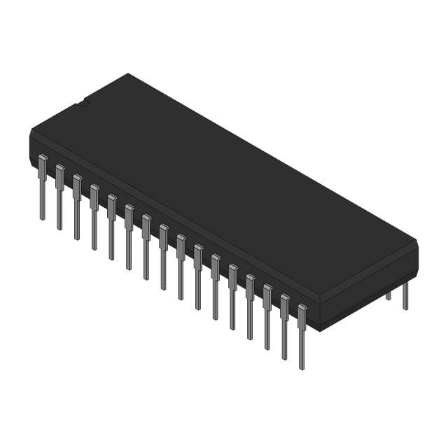
- Part No.:
- SDC1768411
- Manufacturer:
- Analog Devices Inc.
- Category:
- Analog to Digital Converters (ADC)
- Package:
- 32-DIP (0.900", 22.90mm)
- Datasheet:
-
 SDC1768411.pdf
- Description:
- 14-BIT SYNC-TO-DIGITAL CONVERTER
- Quantity:
- Payment:

- Shipping:

Inventory:1,777
Please send an inquiry. Send us your inquiry, and we will respond immediately.
Product details
Overview
SDC1768411 from Analog Devices is a 14-bit hybrid synchro/resolver-to-digital converter with ±5.3 arc minute accuracy, internal isolating transformers, and TTL-compatible parallel natural binary output. It operates over –55°C to +125°C, supports 400 Hz or 2.6 kHz reference frequency, and delivers analog velocity and error outputs for real-time shaft angle tracking in high-reliability servo systems.
For engineers reviewing the SDC1768411 datasheet, SDC1768411 pinout, SDC1768411 application, or SDC1768411 equivalent, this page provides verified technical context, pin-level design meaning, real-world use cases in avionics and fire control, and validated alternative options for resolver interface redesigns requiring hermetic sealing and MIL-qualified reliability.
Technical Context
The SDC1768411 implements a Type II servo loop architecture with phase-sensitive detection, integrator, and voltage-controlled oscillator (VCO) to continuously null Sin(θ − φ), enabling true continuous tracking even during data transfer. Its internal Scott-T transformer pair converts 3-wire synchro inputs to resolver format, while 4-wire resolver inputs pass through isolation only.
It features separate ENABLE_M (pins 29–32) and ENABLE_L (pins 25–28) controls for independent gating of MSB and LSB groups, and uses a dual-monostable latch clocking scheme synchronized to INHIBIT to preserve loop integrity - ensuring no disruption to internal conversion during digital readout.
Key Specifications
| Parameter | Value and Actual Design Meaning |
|---|---|
| Resolution | 14 bits (1 LSB = 1.3 arc minutes); enables sub-degree angular discrimination in precision axis transformation. |
| Accuracy | ±5.3 arc minutes max over full temperature range; meets stringent requirements for artillery fire control and engine controller feedback. |
| Tracking Rate | 18 RPS minimum; supports rapid shaft motion without loss of lock in dynamic servo mechanisms. |
| Transformer Isolation | 350 V dc signal/reference isolation; eliminates ground loops and enables safe operation in high-noise avionic power environments. |
| Output Format | 14-bit parallel natural binary, three-state latched; allows multiplexed bus sharing across multiple converters without external logic. |
| Velocity Output | Analog voltage proportional to input angular velocity (±10 V at max tracking rate); used for closed-loop damping and motion profiling. |
| Error Output | Built-in test point: <±30 mV normal operation, >±200 mV on tracking failure or excessive acceleration; enables real-time fault detection. |
Pinout & Package
SDC1768411 is housed in a hermetically sealed metal 32-pin dual-in-line (DIP) package measuring 1.74″ × 1.14″ × 0.28″ (44.2 × 28.9 × 7.1 mm), with glass-bead standoffs and case-connected pin 32 for EMI shielding and thermal grounding.
| Pin/Terminal | Circuit Role | Design Meaning |
|---|---|---|
| 1–14 | Digital Output (MSB to LSB) | Pins 1–8 = MSB group (ENABLE_M controlled); pins 9–14 = LSB group (ENABLE_L controlled); all TTL-compatible, three-state buffered. |
| 15, 16 | Power Supply | +15 V and –15 V analog supplies; must not be reversed; require local 0.1 µF + 6.8 µF decoupling per rail. |
| 17 | +5 V Digital Supply | Supplies logic circuitry and latches; must remain ≥0 V relative to GND to prevent latch corruption. |
| 18 | GND | Common analog/digital reference; connects to system star ground; pin 32 (Case) must also be grounded. |
| 19, 20 | RHI / RLO | Reference input terminals; accept 11.5 V, 26 V, or 11.8 V rms; isolated up to 350 V dc. |
| 21–24 | S1–S4 | Resolver signal inputs (S1/S2 = sine, S3/S4 = cosine); accept 90 V, 26 V, or 11.8 V rms; isolated up to 350 V dc. |
| 25–28 | ENABLE_L | Active-low enable for LSB group (pins 9–14); allows selective bus access without disturbing MSB readout. |
| 29–32 | ENABLE_M | Active-low enable for MSB group (pins 1–8); supports time-multiplexed 14-bit reads in two cycles. |
| 30 | INHIBIT | Active-low input that freezes latch update without opening servo loop; guarantees data validity after 3 µs. |
| 31 | BUSY | Open-collector output pulses high (≤1.2 µs typ) during counter/latch settling; indicates when data is unstable. |
Key Features
| Feature | Design Value |
|---|---|
| Internal Isolating Transformers | Eliminates need for external isolation components; enables direct connection to high-voltage synchro/resolver windings while maintaining signal integrity. |
| Continuous Tracking During Data Transfer | Maintains closed-loop operation regardless of INHIBIT or ENABLE state; prevents position drift during readout in real-time control loops. |
| Laser-Trimmed Accuracy | No external calibration required; ±5.3 arc minute accuracy achieved via factory laser trimming of internal resistors and gain paths. |
| Hermetic Metal DIP Packaging | Meets MIL-STD-883 Class B screening when ordered with /883B suffix; ensures long-term reliability in aerospace and defense deployments. |
| Velocity & Error Outputs | Provides analog feedback signals directly tied to internal control loop dynamics - usable for adaptive damping and built-in test without external computation. |
Applications
| Avionic Flight Control | Artillery Fire Control |
|---|---|
|
Use Scenario: Real-time measurement of aircraft control surface position (elevator, rudder) under high-G maneuvering and EMI-rich cockpit environments. IC Role / Device Role / Timing Role: Resolver-to-digital converter providing continuous, isolated angular feedback to flight control computers with <55 ms step response. Use Value: Enables deterministic closed-loop actuation using 14-bit resolution and ±5.3 arc minute accuracy - critical for meeting DO-178C/DO-254 certification requirements. |
Use Scenario: Azimuth and elevation angle acquisition for mobile howitzer turret positioning under vibration, shock, and wide ambient temperature swings. IC Role / Device Role / Timing Role: Synchro-to-digital interface converting legacy gun-mount synchro signals into digital commands for fire solution processors. Use Value: Internal transformers withstand 350 V dc transients; hermetic package survives –55°C to +125°C operation without condensation or seal degradation. |
| Engine Controller Feedback | Antenna Position Monitoring |
|
Use Scenario: Monitoring turbine shaft angle and rotational velocity in jet engine FADEC systems where EMI immunity and long-term stability are mandatory. IC Role / Device Role / Timing Role: Resolver interface delivering both digital angle word and analog velocity output for dual-path control law implementation. Use Value: Velocity output scales linearly with angular speed (±10 V at max tracking rate), eliminating need for external differentiators and reducing latency. |
Use Scenario: Precision tracking of radar dish orientation in naval surveillance systems exposed to salt fog, humidity, and mechanical shock. IC Role / Device Role / Timing Role: High-reliability synchro-to-digital converter feeding position data to stabilization algorithms in real time. Use Value: Error output transitions >±200 mV on loss of track - triggers immediate fault logging and failsafe repositioning without software polling. |
Equivalent & Alternatives
The following parts are listed as comparable options for similar resolver-to-digital conversion applications.
| Alternative Part | Technical Difference | Application Difference | Selection Advice |
|---|---|---|---|
| SDC1767411 | 12-bit resolution (5.3 arc min LSB), ±8.5 arc min accuracy, lower tracking rate (36 RPS), same pinout and package. | Lower angular precision; suitable for non-critical coordinate conversion where cost sensitivity outweighs resolution needs. | Select when 12-bit resolution suffices and velocity/error outputs are still required - identical footprint and interface reduce redesign effort. |
| DRC1765 | 14-bit digital-to-resolver converter (reverse function), no analog velocity/error outputs, ±2 arc min accuracy, requires external reference. | Unidirectional digital-to-analog conversion only; cannot replace SDC1768411 in sensor feedback roles. | Consider only for complementary DAC-based excitation circuits - not a functional substitute for resolver-to-digital sensing. |
Compared with SDC1768411, SDC1767411 offers identical interface and packaging but trades 2 bits of resolution and 3.2 arc min accuracy for lower cost and higher tracking rate; DRC1765 serves an inverse function entirely and lacks isolation, velocity, or error monitoring - making it unsuitable as a drop-in or functional alternative.
Availability
SDC1768411 is available at Aetrix Electronics and suitable for avionic flight control, artillery fire control, and engine controller feedback applications requiring stable component supply, long-lifecycle assurance, and MIL-qualified reliability.
Supply support for SDC1768411 includes scheduled delivery planning, volume procurement assistance, BOM continuity management, traceable sourcing, and lifecycle availability coordination for OEM customers, industrial embedded developers, connected-device designers, and electronics production programs.
Manufacturer
Analog Devices is a global semiconductor company specializing in high-performance analog, mixed-signal, and digital signal processing technologies for precision measurement and control.
The SDC/RDC1768 family was designed for demanding military and aerospace motion feedback systems requiring hermetic packaging, transformer isolation, and continuous tracking - targeting resolver/synchro interfacing where reliability trumps cost.
FAQ
What is the operating temperature range of the SDC1768411?
The SDC1768411 operates from –55°C to +125°C and is storage-rated from –65°C to +150°C. This extended range is achieved through hermetic metal packaging and MIL-STD-883 Class B screening when ordered with the /883B suffix. The SDC1768411 maintains its ±5.3 arc minute accuracy across this full range, making it suitable for deployment in jet engines, missile guidance, and tracked vehicle systems.
Does the SDC1768411 support both synchro and resolver inputs?
Yes, the SDC1768411 supports both 3-wire synchro (via S1–S3) and 4-wire resolver (via S1–S4) inputs, determined by the Z-option code in the part number. For SDC1768411, the "Z=1" option specifies 11.8 V signal and reference compatibility with resolver format. Internal Scott-T transformers convert synchro signals to resolver-equivalent format, while resolver inputs pass through isolation only.
How does the INHIBIT function affect the internal servo loop of the SDC1768411?
The INHIBIT input on the SDC1768411 freezes latch updates without disrupting the internal Type II servo loop - the VCO, integrator, and error amplifier continue running uninterrupted. When INHIBIT is asserted low, the up-down counter keeps tracking the input shaft angle, and data becomes valid 3 µs after assertion. This preserves dynamic performance during readout, unlike gated-clock approaches that break loop continuity.
What is the purpose of the ERROR output on the SDC1768411?
The ERROR output on the SDC1768411 is a built-in test point derived near the Sin(θ − φ) null point of the internal control loop. Under normal operation, it remains below ±30 mV; if tracking fails or input acceleration exceeds design limits, it rapidly transitions to >±200 mV. It is not linear with error and must not be used for closed-loop correction - only for fault detection and system-level diagnostics.
Can the SDC1768411 be used with non-standard signal or reference voltages?
Yes, the SDC1768411 supports resistive scaling of signal and reference inputs. For resolver mode, add 2.22 kΩ per extra volt in series with S1/S2, and 1 kΩ per extra volt in series with RHI. This allows adaptation to custom voltage levels without modifying the core converter - a key feature enabling reuse across platforms with varying synchro/resolver excitation standards.
SDC1768411 Specifications
- Product attributes
- Attribute value
- Manufacturer:
- Analog Devices Inc.
- Series:
- SDC1768
- Package/Case:
- 32-DIP (0.900", 22.90mm)
- Packaging:
- Bulk
- Product Status:
- Active
- Number of Bits:
- 14
- Sampling Rate (Per Second):
- -
- Number of Inputs:
- 4
- Input Type:
- Single Ended
- Data Interface:
- Parallel
- Configuration:
- -
- Ratio - S/H:ADC:
- -
- Number of A/D Converters:
- -
- Architecture:
- -
- Reference Type:
- External, Internal
- Voltage - Supply, Analog:
- -
- Voltage - Supply, Digital:
- -
- Features:
- -
- Operating Temperature:
- -55°C ~ 125°C
- Supplier Device Package:
- 32-DIP
- Mounting Type:
- Through Hole
- Grade:
- -
- Qualification:
- -
SDC1768411 FAQ
1.How can I place an order for SDC1768411 through Aetrix?
Please submit a Request for Quotation (RFQ) for SDC1768411 on Aetrix. Our sales agent will provide a competitive quotation and guide you through the order confirmation once you accept the terms.
2.Are the price and stock information for SDC1768411 reliable?
The price and inventory of SDC1768411 are updated periodically and may fluctuate due to market conditions. Stock and pricing data are typically refreshed every 24 hours. Quotation validity for SDC1768411 is usually 5 days.
3.What payment methods are accepted for SDC1768411?
We accept Wire Transfer, PayPal, Credit Card, Western Union, MoneyGram, and Escrow for SDC1768411 transactions.
Note: Certain payment methods may incur a processing fee.
4.How is shipping managed for SDC1768411?
SDC1768411 orders can be shipped via leading logistics carriers, including DHL, UPS, FedEx, TNT, or Registered Mail.
Once your SDC1768411 order is processed, you will receive an email with the shipment details and tracking number.
Note: Tracking information may take up to 24 hours to appear. Express delivery typically takes 3–5 business days.
5.How can I obtain technical support or documentation for SDC1768411?
For technical support, including SDC1768411 datasheets, pinout diagrams, or application guidance, please contact our engineering support team. They can provide detailed documentation and assistance for your SDC1768411 requirements.
6.How does Aetrix verify that SDC1768411 is sourced from the original manufacturer or authorized distributors?
All SDC1768411 products on Aetrix are procured from qualified distributors and authorized channels. Our dedicated quality assurance team conducts strict verification, including traceability checks and, if necessary, third-party testing. This ensures that SDC1768411 meets industry standards.
7.What is the process for return or replacement of SDC1768411?
All SDC1768411 units undergo pre-shipment inspection (PSI). If there is an issue with SDC1768411, returns or replacements are accepted under the following conditions:
1.Quantity discrepancies, incorrect items, or visible external defects (such as breakage or corrosion), acknowledged by Aetrix.
2.The issue is reported within 90 days of delivery.
3.The SDC1768411 part is unused and in its original packaging.
Return procedure for SDC1768411:
1.Submit a request within 90 days.
2.Obtain a Return Material Authorization (RMA) from Aetrix.
SDC1768411 Tags
-
ADC081C021CIMKX/NOPB
Texas Instruments

-
MCP3021A5T-E/OT
Microchip Technology
-
TLA2024IRUGR
Texas Instruments
-
MCP3221A5T-E/OT
Microchip Technology
-
MCP3221A5T-I/OT
Microchip Technology
-
MCP3221A4T-E/OT
Microchip Technology
-
MCP3221A6T-E/OT
Microchip Technology
-
MCP3221A0T-E/OT
Microchip Technology
-
MCP3221A1T-E/OT
Microchip Technology

-
ADC121S021CIMFX/NOPB
Texas Instruments

-
MCP3001-I/MS
Microchip Technology

-
MCP3001-I/SN
Microchip Technology
Tech Hub

A practical engineering guide to 3.3V and 5V logic compatibility, input thresholds, resistor dividers, translator ICs, MOSFET level shifting, I2C pull-ups, timing limits and power-sequencing risks.

The 74HC595 uses push-pull logic outputs, while the TPIC6B595 uses 50 V open-drain DMOS sinks for higher-power loads. This guide compares timing, current limits, 3.3 V interfacing, load wiring, thermal…

The 74HC595 converts serial data into eight stable parallel outputs. This guide covers pin functions, shift and storage timing, OE and MR behavior, drive-current limits, cascading, voltage compatibilit…

A technical comparison of level-sensitive latches and edge-triggered flip-flops, covering timing windows, setup and hold limits, master–slave operation, time borrowing, race-through, HDL inference and…

A D latch stores one bit while Enable controls when data can pass. This reference covers gate-level operation, truth tables, transparency, setup and hold timing, LE versus OE, common ICs and practical …

An SR latch stores one bit through cross-coupled feedback. This engineering reference covers NOR and NAND implementations, truth tables, forbidden-state recovery, gated operation, switch debouncing, fa…

Latch circuits retain one bit through feedback. This technical reference covers SR and D latches, truth tables, transparency, timing limits, latch-versus-flip-flop behavior, applications and common log…

An engineering guide to LED driver operation, constant-current and constant-voltage outputs, linear and switching topologies, dimming, IC selection, calculations, replacement compatibility, and fault c…

Operational amplifier guide covering op amp basics, feedback, ideal vs real op amps, common configurations, buffer circuits, offset, bias current, gain-bandwidth, slew rate, rail-to-rail limits and sel…

Jumper cables guide covering safe connection order, red and black clamp placement, final ground connection, cable gauge, length, clamp quality, copper vs CCA cables, jump starter comparison and battery…


