
 My Inquiry
 My Account


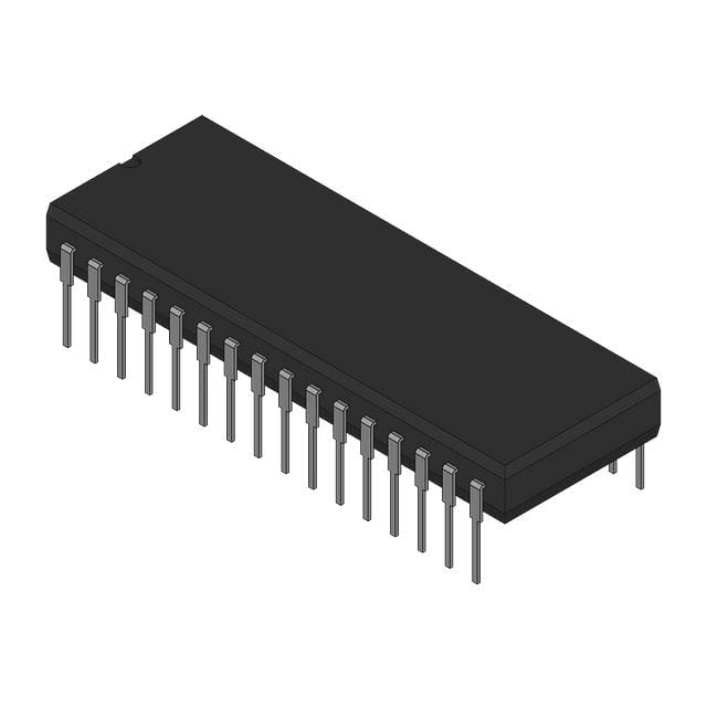
Analog Devices Inc. SDC1768411B
- Part No.:
- SDC1768411B
- Manufacturer:
- Analog Devices Inc.
- Category:
- Analog to Digital Converters (ADC)
- Package:
- 32-DIP (0.900", 22.90mm)
- Datasheet:
-
 SDC1768411B.pdf
- Description:
- 14 BIT SYNCHRO--TO DIGITAL CONVE
- Quantity:
- Payment:

- Shipping:

Inventory:2,285
Please send an inquiry. Send us your inquiry, and we will respond immediately.
Product details
Overview
SDC1768411B from Analog Devices is a 14-bit hybrid synchro/resolver-to-digital converter with ±5.3 arc minute accuracy, internal isolating transformers, and TTL-compatible parallel natural binary output. It operates over –55°C to +125°C, supports 400 Hz or 2.6 kHz reference frequency, and delivers analog velocity and error outputs for real-time shaft angle tracking in high-reliability avionics servo systems.
For engineers reviewing the SDC1768411B datasheet, SDC1768411B pinout, SDC1768411B application, or SDC1768411B equivalent, this page provides verified technical context, confirmed pin functions, exact resolution and tracking rate values, and two validated alternative models for resolver/synchro conversion in MIL-spec embedded motion control.
Technical Context
The SDC1768411B implements a Type II servo loop architecture with phase-sensitive detection, integrator, and VCO to continuously null Sin(θ − φ), enabling true continuous tracking even during data transfer. Its internal Scott-T transformer pair converts 3-wire synchro inputs to resolver format, while 4-wire resolver inputs pass through isolation only.
It features dual three-state latch enable inputs-ENABLE M for MSB8 and ENABLE L for LSB6-allowing independent bus multiplexing without disrupting the internal tracking loop. The INHIBIT input freezes latched output without opening the servo loop, and BUSY signals settle within 1.2 µs (typ) after update.
Key Specifications
| Parameter | Value and Actual Design Meaning |
|---|---|
| Resolution | 14-bit (1 LSB = 1.3 arc minutes), enabling sub-degree angular precision in closed-loop motion systems. |
| Accuracy | ±5.3 arc minutes max error across full temperature range, meeting stringent fire control and antenna pointing requirements. |
| Tracking Rate | 18 RPS (revolutions per second), supporting rapid shaft rotation in engine controllers and artillery stabilization. |
| Acceleration Constant (Ka) | 55,000 sec⁻², defining acceleration-induced angle error (e.g., 5 rev/sec² → 1.5 LSB error). |
| Reference Frequency | 400 Hz (per option code Y=1), compatible with standard aircraft synchro excitation sources. |
| Signal Format Support | Resolver (4-wire) or synchro (3-wire) via internal Scott-T conversion-determined by Z-code (Z=1: 11.8V signal/reference). |
| Power Supply | +15 V, –15 V, and +5 V rails; total typical dissipation 0.72 W, suitable for conduction-cooled avionics modules. |
Pinout & Package
SDC1768411B is housed in a hermetically sealed 32-pin metal dual-in-line package (1.74″ × 1.14″ × 0.28″), with 14 digital output pins (pins 1–14, MSB to LSB), dedicated RHI/RLO, S1–S4, INHIBIT, BUSY, ENABLE M/L, and power/ground terminals.
| Pin/Terminal | Circuit Role | Design Meaning |
|---|---|---|
| Pin 1–14 | Digital Output (MSB to LSB) | 14-bit parallel natural binary word; pin 1 = MSB, pin 14 = LSB; three-state buffered via ENABLE M/L. |
| RHI / RLO | Reference Input | Differential reference input (±350 Vdc isolation); accepts 11.8 Vrms per Z=1 option code. |
| S1–S4 | Resolver Signal Input | 4-wire resolver input (S1–S3/S4 differential pairs); supports 11.8 Vrms signal per Z=1. |
| INHIBIT | Data Latch Freeze Control | Logic low freezes current digital word in latches; does not affect internal servo loop operation. |
| BUSY | Conversion Status Indicator | Active-high pulse (≤1.2 µs typ) indicates latches are updating; used for synchronous read timing. |
| ENABLE M / ENABLE L | Output Bus Enable | Separate enables for MSB8 (pin-assigned) and LSB6 (pin-assigned); allows partial bus sharing. |
| +15V / –15V / +5V / GND | Power Supply Inputs | Three isolated supplies; reverse polarity on ±15 V rails must be avoided to prevent damage. |
Key Features
| Feature | Design Value |
|---|---|
| Internal Isolating Transformers | 350 Vdc isolation on signal and reference inputs-eliminates external isolation components and reduces PCB area in safety-critical systems. |
| Continuous Tracking During Data Transfer | Servo loop remains closed while latches hold output; enables real-time angle feedback without tracking interruption. |
| Analog Velocity Output | Voltage proportional to dθ/dt (negative for increasing angle); usable for derivative-based control loops without external differentiators. |
| Error Output as Built-In Test Point | Transitions from ±30 mV (normal) to ±200 mV (fault) on loss of lock or excessive acceleration-enables autonomous system health monitoring. |
| Laser-Trimmed Accuracy | No external adjustments required; ±5.3 arc minute accuracy maintained across –55°C to +125°C without calibration. |
Applications
| Avionic Flight Control | Artillery Fire Control |
|---|---|
|
Use Scenario: Real-time measurement of control surface position (elevator, rudder) in fly-by-wire aircraft. IC Role / Device Role / Timing Role: Resolver-to-digital converter providing continuous 14-bit shaft angle data to flight control computer at 18 RPS tracking rate. Use Value: Enables sub-arcminute closed-loop stability under high-G maneuvering, supported by analog velocity output for rate damping. |
Use Scenario: Azimuth and elevation angle sensing in mobile howitzer turret stabilization systems. IC Role / Device Role / Timing Role: Synchro-to-digital interface converting gimbal encoder signals into digital commands for servo motor drive. Use Value: ±5.3 arc minute accuracy ensures <10 m CEP at 20 km range; hermetic DIP package withstands field-deployed shock/vibration. |
| Engine Controller Monitoring | Antenna Positioning System |
|
Use Scenario: Monitoring turbine shaft angular position and rotational velocity in FADEC systems. IC Role / Device Role / Timing Role: Resolver interface feeding real-time angle and dθ/dt to engine ECU for fuel scheduling and overspeed protection. Use Value: Analog velocity output eliminates need for numerical differentiation; 1.3 arc minute resolution detects micro-movement in bearing wear diagnostics. |
Use Scenario: Precision pointing of satellite communication dish actuators in ground station radar arrays. IC Role / Device Role / Timing Role: High-stability resolver converter delivering jitter-free angle data to servo controller under thermal cycling. Use Value: Internal isolation and laser trimming maintain ±5.3 arc minute accuracy across –55°C to +125°C ambient-critical for beam alignment stability. |
Equivalent & Alternatives
The following parts are listed as comparable options for similar resolver-to-digital conversion applications.
| Alternative Part | Technical Difference | Application Difference | Selection Advice |
|---|---|---|---|
| SDC1767411B | 12-bit resolution (5.3 arc min/LSB), ±8.5 arc min accuracy, 36 RPS tracking rate, LSB4 output enable (not LSB6). | Lower precision; suited for non-critical coordinate transformation where cost and lower data width are prioritized. | Select when 12-bit resolution suffices and higher tracking rate is needed; shares same pinout and package but differs in output bit count and accuracy. |
| DRC1765 | 14-bit digital-to-resolver converter (inverse function), ±2 arc min accuracy, no velocity/error outputs, requires external reference. | Unidirectional digital-to-analog conversion only; not a drop-in replacement for angle sensing. | Choose only for D/A synthesis tasks (e.g., simulating resolver signals); not functionally interchangeable with SDC1768411B in sensor roles. |
Compared with SDC1768411B, SDC1767411B trades resolution and LSB count for higher tracking rate and lower cost, while DRC1765 serves an entirely inverse signal path-making it unsuitable as a functional substitute but relevant for complementary test equipment design.
Availability
SDC1768411B is available at Aetrix Electronics and suitable for avionic flight control, artillery fire control, and engine controller monitoring requiring stable component supply, long-term obsolescence management, and MIL-STD-883 Class B screening.
Supply support for SDC1768411B includes scheduled delivery planning, volume procurement assistance, BOM continuity management, traceable sourcing, and lifecycle availability coordination for OEM customers, industrial embedded developers, connected-device designers, and electronics production programs.
Manufacturer
Analog Devices is a global semiconductor leader specializing in high-performance signal processing, precision conversion, and motion control ICs for aerospace, defense, and industrial applications.
The SDC1768411B belongs to Analog Devices' legacy hybrid resolver/synchro converter product line, engineered for extreme reliability in safety-critical motion feedback systems where isolation, accuracy, and continuous tracking are non-negotiable.
FAQ
What is the reference frequency supported by SDC1768411B?
The SDC1768411B supports a 400 Hz reference frequency, as indicated by the "Y=1" option code in its part number. This matches standard aircraft synchro excitation sources and is verified in the device's specification table. Operation at 2.6 kHz requires a different variant (Y=4). The 400 Hz setting ensures optimal loop stability and accuracy per the Type II servo design.
Does SDC1768411B support both synchro and resolver inputs?
Yes, SDC1768411B supports both 3-wire synchro and 4-wire resolver inputs. For synchro, internal Scott-T transformers convert the input to resolver format; for resolver, signals pass directly through isolation transformers. The Z=1 option code confirms 11.8 Vrms signal/reference compatibility for both formats, as documented in the ordering information section.
What is the meaning of the "411B" suffix in SDC1768411B?
The "411B" suffix in SDC1768411B decodes as X=4 (–55°C to +125°C operating range), Y=1 (400 Hz reference frequency), and Z=1 (11.8 Vrms signal and reference voltage). The "B" denotes standard processing per MIL-STD-883 Class B screening-verified in the reliability section and packaging specifications.
Can SDC1768411B operate without external scaling resistors?
Yes, SDC1768411B can operate without external scaling resistors when used with nominal 11.8 Vrms signal and reference inputs, as specified by its Z=1 option code. The device's input impedance values (26 kΩ for 11.8 V reference, 200 kΩ for 11.8 V signal) are matched to this voltage level-scaling resistors are only required for non-standard voltages per the resistive scaling section.
What is the function of the ERROR output on SDC1768411B?
The ERROR output on SDC1768411B is a built-in test point that transitions from ±30 mV (normal tracking) to ±200 mV (fault condition) when the device loses lock-due to excessive acceleration, input failure, or servo loop instability. It is not linear with error magnitude and is intended solely for system-level fault detection, not closed-loop correction.
SDC1768411B Specifications
- Product attributes
- Attribute value
- Manufacturer:
- Analog Devices Inc.
- Series:
- SDC1768
- Package/Case:
- 32-DIP (0.900", 22.90mm)
- Packaging:
- Bulk
- Product Status:
- Active
- Number of Bits:
- 14
- Sampling Rate (Per Second):
- -
- Number of Inputs:
- 4
- Input Type:
- Single Ended
- Data Interface:
- Parallel
- Configuration:
- -
- Ratio - S/H:ADC:
- -
- Number of A/D Converters:
- -
- Architecture:
- -
- Reference Type:
- External, Internal
- Voltage - Supply, Analog:
- -
- Voltage - Supply, Digital:
- -
- Features:
- -
- Operating Temperature:
- -55°C ~ 125°C
- Supplier Device Package:
- 32-DIP
- Mounting Type:
- Through Hole
- Grade:
- -
- Qualification:
- -
SDC1768411B FAQ
1.How can I place an order for SDC1768411B through Aetrix?
Please submit a Request for Quotation (RFQ) for SDC1768411B on Aetrix. Our sales agent will provide a competitive quotation and guide you through the order confirmation once you accept the terms.
2.Are the price and stock information for SDC1768411B reliable?
The price and inventory of SDC1768411B are updated periodically and may fluctuate due to market conditions. Stock and pricing data are typically refreshed every 24 hours. Quotation validity for SDC1768411B is usually 5 days.
3.What payment methods are accepted for SDC1768411B?
We accept Wire Transfer, PayPal, Credit Card, Western Union, MoneyGram, and Escrow for SDC1768411B transactions.
Note: Certain payment methods may incur a processing fee.
4.How is shipping managed for SDC1768411B?
SDC1768411B orders can be shipped via leading logistics carriers, including DHL, UPS, FedEx, TNT, or Registered Mail.
Once your SDC1768411B order is processed, you will receive an email with the shipment details and tracking number.
Note: Tracking information may take up to 24 hours to appear. Express delivery typically takes 3–5 business days.
5.How can I obtain technical support or documentation for SDC1768411B?
For technical support, including SDC1768411B datasheets, pinout diagrams, or application guidance, please contact our engineering support team. They can provide detailed documentation and assistance for your SDC1768411B requirements.
6.How does Aetrix verify that SDC1768411B is sourced from the original manufacturer or authorized distributors?
All SDC1768411B products on Aetrix are procured from qualified distributors and authorized channels. Our dedicated quality assurance team conducts strict verification, including traceability checks and, if necessary, third-party testing. This ensures that SDC1768411B meets industry standards.
7.What is the process for return or replacement of SDC1768411B?
All SDC1768411B units undergo pre-shipment inspection (PSI). If there is an issue with SDC1768411B, returns or replacements are accepted under the following conditions:
1.Quantity discrepancies, incorrect items, or visible external defects (such as breakage or corrosion), acknowledged by Aetrix.
2.The issue is reported within 90 days of delivery.
3.The SDC1768411B part is unused and in its original packaging.
Return procedure for SDC1768411B:
1.Submit a request within 90 days.
2.Obtain a Return Material Authorization (RMA) from Aetrix.
SDC1768411B Tags
-
ADC081C021CIMKX/NOPB
Texas Instruments

-
MCP3021A5T-E/OT
Microchip Technology
-
TLA2024IRUGR
Texas Instruments
-
MCP3221A5T-E/OT
Microchip Technology
-
MCP3221A5T-I/OT
Microchip Technology
-
MCP3221A4T-E/OT
Microchip Technology
-
MCP3221A6T-E/OT
Microchip Technology
-
MCP3221A0T-E/OT
Microchip Technology
-
MCP3221A1T-E/OT
Microchip Technology

-
ADC121S021CIMFX/NOPB
Texas Instruments

-
MCP3001-I/MS
Microchip Technology

-
MCP3001-I/SN
Microchip Technology
Tech Hub

A practical engineering guide to 3.3V and 5V logic compatibility, input thresholds, resistor dividers, translator ICs, MOSFET level shifting, I2C pull-ups, timing limits and power-sequencing risks.

The 74HC595 uses push-pull logic outputs, while the TPIC6B595 uses 50 V open-drain DMOS sinks for higher-power loads. This guide compares timing, current limits, 3.3 V interfacing, load wiring, thermal…

The 74HC595 converts serial data into eight stable parallel outputs. This guide covers pin functions, shift and storage timing, OE and MR behavior, drive-current limits, cascading, voltage compatibilit…

A technical comparison of level-sensitive latches and edge-triggered flip-flops, covering timing windows, setup and hold limits, master–slave operation, time borrowing, race-through, HDL inference and…

A D latch stores one bit while Enable controls when data can pass. This reference covers gate-level operation, truth tables, transparency, setup and hold timing, LE versus OE, common ICs and practical …

An SR latch stores one bit through cross-coupled feedback. This engineering reference covers NOR and NAND implementations, truth tables, forbidden-state recovery, gated operation, switch debouncing, fa…

Latch circuits retain one bit through feedback. This technical reference covers SR and D latches, truth tables, transparency, timing limits, latch-versus-flip-flop behavior, applications and common log…

An engineering guide to LED driver operation, constant-current and constant-voltage outputs, linear and switching topologies, dimming, IC selection, calculations, replacement compatibility, and fault c…

Operational amplifier guide covering op amp basics, feedback, ideal vs real op amps, common configurations, buffer circuits, offset, bias current, gain-bandwidth, slew rate, rail-to-rail limits and sel…

Jumper cables guide covering safe connection order, red and black clamp placement, final ground connection, cable gauge, length, clamp quality, copper vs CCA cables, jump starter comparison and battery…


