
 My Inquiry
 My Account


Skyworks Solutions Inc. SI5338C-B04404-GM
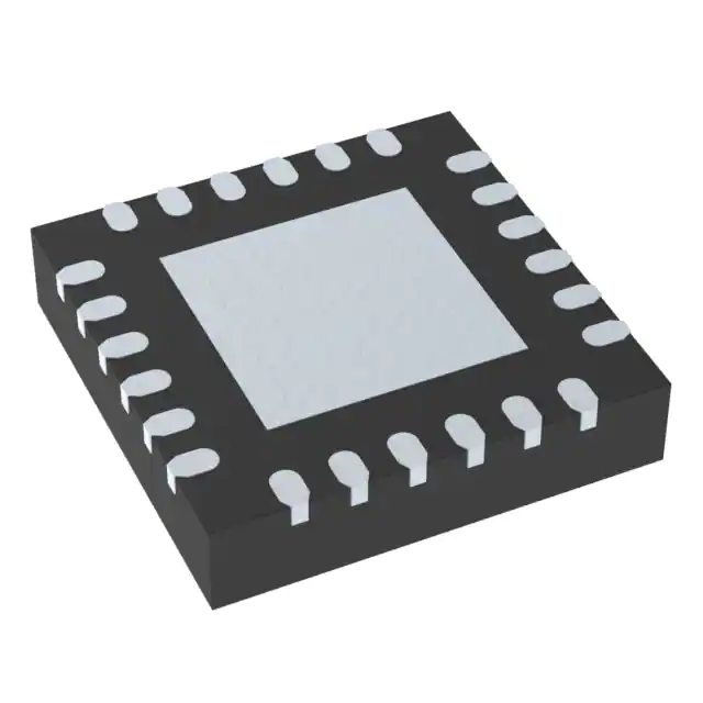
- Part No.:
- SI5338C-B04404-GM
- Manufacturer:
- Skyworks Solutions Inc.
- Category:
- Application Specific Clock/Timing
- Package:
- 24-VFQFN Exposed Pad
- Datasheet:
-
 SI5338C-B04404-GM.pdf
- Description:
- I2C CONTROL, 4-OUTPUT, ANY FREQU
- Quantity:
- Payment:

- Shipping:

Inventory:2,263
Please send an inquiry. Send us your inquiry, and we will respond immediately.
Product details
Overview
SI5338C-B04404-GM from Skyworks Solutions is a quad-output, I²C-programmable clock generator with MultiSynth™ frequency synthesis. It delivers four independent, any-frequency differential or single-ended clocks (0.16–710 MHz), supports PCIe Gen 1–4 Common Clock and Gen 3 SRNS compliance, achieves 0.7 ps RMS typical phase jitter, and operates from 1.8/2.5/3.3 V core supply in a 4 × 4 mm 24-QFN package. It is used in high-speed serial interface timing for FPGA-based telecom line cards.
For engineers reviewing the SI5338C-B04404-GM datasheet, SI5338C-B04404-GM pinout, SI5338C-B04404-GM application, or SI5338C-B04404-GM equivalent, key selection criteria include PCIe Gen 4 jitter compliance (0.15–0.45 ps RMS), independent output voltage per driver (1.5/1.8/2.5/3.3 V), flexible input reference support (8–30 MHz crystal, up to 710 MHz differential), and programmable phase/frequency adjustment in <20 ps / 1 ppm steps.
Technical Context
The SI5338C-B04404-GM implements a two-stage PLL architecture: a high-stability integer-N PLL (Stage 1) locks to an external reference, followed by four independent MultiSynth™ fractional-N synthesizers (Stage 2) generating each output. Each synthesizer supports integer or fractional mode, enabling true zero-ppm accuracy and fine-grained frequency resolution down to 1 ppb.
Its output stage provides configurable drivers supporting LVPECL/LVDS/HCSL/CMOS/SSTL/HSTL formats, with independent VDDO supplies per bank (VDDO0–VDDO3), programmable spread spectrum (0.5–5.0% at 33–63 kHz), loss-of-lock and loss-of-signal alarms, and glitchless frequency increment/decrement via dedicated pins or I²C.
Key Specifications
| Parameter | Value and Actual Design Meaning |
|---|---|
| Phase Jitter (RMS) | 0.7 ps typical (12 kHz–20 MHz); meets PCIe Gen 4 common clock jitter spec (≤0.45 ps RMS). |
| Output Frequency Range | 0.16–710 MHz per channel; supports up to two outputs >350 MHz simultaneously (Fvco/4 & Fvco/6). |
| Input Reference Support | Crystal (8–30 MHz), CMOS (5–200 MHz), SSTL/HSTL (5–350 MHz), differential (5–710 MHz). |
| Supply Voltages | Core: 1.8/2.5/3.3 V ±10%; Output buffers: independently configurable 1.4–3.63 V per VDDOx pin. |
| Temperature Range | –40 °C to +85 °C; qualified for industrial embedded and telecom line card environments. |
| Package | 24-pin QFN, 4 × 4 mm, 0.5 mm pitch; exposes thermal pad for enhanced thermal dissipation (θJA = 37 °C/W). |
| Power Consumption | 45 mA typical core current at 100 MHz on all outputs and 25 MHz refclk; <12 mA in buffer-only mode. |
Pinout & Package
SI5338C-B04404-GM is housed in a 24-lead, 4 × 4 mm QFN package with exposed thermal pad. Pin assignments follow the standard Si5338 top-view layout: IN1/IN2 (differential input 1), IN3/IN4 (single-ended inputs), IN5/IN6 (differential input 2), CLK0A/CLK0B through CLK3A/CLK3B (four differential output pairs), VDDO0–VDDO3 (independent output supply pins), VDD (core supply), SCL/SDA/INTR (I²C interface and interrupt), and GND/RSVD_GND.
| Pin/Terminal | Circuit Role | Design Meaning |
|---|---|---|
| CLK0A / CLK0B | Differential output pair 0 | LVPECL/LVDS/HCSL/CML-capable; driven by MultiSynth 0; voltage set by VDDO0. |
| CLK1A / CLK1B | Differential output pair 1 | Independent frequency/format control; driven by MultiSynth 1; voltage set by VDDO1. |
| CLK2A / CLK2B | Differential output pair 2 | Supports up to 710 MHz (LVPECL) or 250 MHz (HCSL); driven by MultiSynth 2; voltage set by VDDO2. |
| CLK3A / CLK3B | Differential output pair 3 | Configurable for PCIe Gen 4 reference clock; driven by MultiSynth 3; voltage set by VDDO3. |
| VDDO0–VDDO3 | Output buffer supply rails | Enable mixed-voltage system timing: e.g., CLK0 at 1.8 V for FPGA I/O, CLK2 at 3.3 V for legacy PHY. |
| SCL / SDA | I²C serial interface | Supports SMBus-compatible programming; allows full configuration including frequency, format, SSC, and phase offset. |
| INTR | Interrupt output | Asserts low on loss-of-lock or loss-of-signal; enables real-time system fault monitoring without polling. |
| IN1/IN2, IN5/IN6 | Differential reference inputs | Accept 5–710 MHz AC-coupled signals; internal 10 kΩ termination; optimized for low-jitter injection. |
| IN3/IN4 | Single-ended reference inputs | Accept 5–200 MHz CMOS-level clocks; 20 kΩ internal pull-up/down options; slew-rate sensitive for jitter performance. |
Key Features
| Feature | Design Value |
|---|---|
| MultiSynth™ synthesis per output | Enables four truly independent, any-frequency clocks (0.16–710 MHz) with 0 ppm error - replaces multiple discrete oscillators. |
| PCIe Gen 4 Common Clock compliance | Meets 0.15–0.45 ps RMS jitter requirement at 100 MHz HCSL output, verified with Intel Clock Jitter Tool and AN562 methodology. |
| Independent output voltage per driver | Four VDDO pins allow simultaneous 1.8 V (FPGA), 2.5 V (ASIC), 3.3 V (legacy PHY), and 1.5 V (DDR I/O) clock domains from one IC. |
| Glitchless frequency adjustment | Hardware pin-controlled frequency increment/decrement in 1 ppm steps with ≤667 ns update time - enables dynamic rate adaptation without clock interruption. |
| Programmable phase offset | ±45 ns initial phase shift per output with <20 ps step resolution - critical for skew alignment across multi-lane SerDes interfaces. |
| Spread spectrum on any output | Configurable 0.5–5.0% down-spread at 33–63 kHz modulation rate - reduces EMI peak emissions without affecting timing margin. |
Applications
| Ethernet Switch/Routing Timing | PCIe Gen 1–4 Clocking |
|---|---|
Use Scenario: High-density 10/25/100 GbE switch fabric requiring synchronized clocks across multiple MAC/PHY/FPGA domains. IC Role / Device Role / Timing Role: Quad-output clock generator providing independent 156.25 MHz (XAUI), 312.5 MHz (CAUI), 125 MHz (GbE), and 100 MHz (PCIe) clocks with sub-1 ps jitter. Use Value: Eliminates four separate oscillators and reduces board area by >60%; maintains PCIe Gen 4 jitter compliance while enabling multi-rate Ethernet timing. | Use Scenario: Server motherboard with CPU, GPU, NVMe SSD, and add-in cards sharing a common reference clock architecture. IC Role / Device Role / Timing Role: PCIe Gen 4-compliant common clock source delivering 100 MHz HCSL to all endpoints with <0.45 ps RMS jitter and loss-of-lock detection. Use Value: Ensures PCIe link training success and long-term reliability; INTR pin enables firmware-triggered clock failover before link degradation occurs. |
| Broadcast Video/Audio Sync | Processor & FPGA Clocking |
Use Scenario: SMPTE 2110 IP video router requiring precise genlock between SDI-to-IP gateways, media processors, and network interfaces. IC Role / Device Role / Timing Role: Any-frequency synthesizer generating 27 MHz (SDI), 74.25 MHz (HD), 148.5 MHz (UHD), and 100 MHz (10GBase-T) from a single 25 MHz crystal reference. Use Value: Achieves frame-accurate synchronization across heterogeneous video subsystems; eliminates need for multiple TCXOs or complex clock trees. | Use Scenario: Xilinx Versal or Intel Agilex FPGA-based edge AI inference platform with heterogeneous compute tiles (AI engines, NoC, DDR, PCIe). IC Role / Device Role / Timing Role: Configurable clock source delivering 500 MHz (PL logic), 300 MHz (NoC), 200 MHz (DDR4 PHY), and 100 MHz (PCIe root port) with independent voltage and format per domain. Use Value: Enables optimal power/performance trade-offs per subsystem; avoids level-shifting components and simplifies PCB routing. |
Equivalent & Alternatives
The following parts are listed as comparable options for similar quad-output programmable clock generator applications.
| Alternative Part | Technical Difference | Application Difference | Selection Advice |
|---|---|---|---|
| Si5338A-B04404-GM | Same pinout and register map; differs only in factory-programmed NVM content (different default frequency configuration). | No functional difference in PCIe Gen 4 or Ethernet timing use cases; identical jitter, frequency range, and feature set. | Select when pre-configured startup frequencies match system requirements out-of-box; SI5338C-B04404-GM requires ClockBuilder Pro programming prior to first use. |
| LMK04832RHAR | Two-stage jitter cleaner + generator; higher integration (integrated LDOs, dual-loop PLL); larger 48-QFN package; higher power (90 mA typical). | Better suited for ultra-low-jitter cleaning of noisy references (e.g., recovered SerDes clocks); less optimal for pure any-frequency generation from clean crystals. | Choose when input reference has >1 ps RMS jitter and system demands sub-0.1 ps RMS cleaned output; SI5338C-B04404-GM excels with clean crystal or differential inputs. |
Compared with Si5338A-B04404-GM, SI5338C-B04404-GM offers identical hardware functionality but requires user programming for custom frequencies, enabling greater design flexibility. Compared with LMK04832RHAR, SI5338C-B04404-GM provides lower power, smaller footprint, and simpler configuration for crystal-referenced systems - making it optimal for cost- and space-constrained PCIe and Ethernet timing.
Availability
SI5338C-B04404-GM is available at Aetrix Electronics and suitable for PCIe Gen 4 server motherboards, 100G Ethernet switch fabrics, and broadcast video routers requiring stable component supply, long-term lifecycle support, and traceable sourcing.
Supply support for SI5338C-B04404-GM includes scheduled delivery planning, volume procurement assistance, BOM continuity management, traceable sourcing, and lifecycle availability coordination for OEM customers, industrial embedded developers, connected-device designers, and electronics production programs.
Manufacturer
Skyworks Solutions is a global leader in analog and mixed-signal semiconductors, specializing in RF, timing, and connectivity solutions for infrastructure, automotive, and mobile markets.
The Si5338 product line was designed specifically for high-performance, multi-protocol timing in datacenter, telecom, and broadcast equipment - emphasizing low jitter, flexible I²C programmability, and compact integration of up to four clock domains.
FAQ
What is the default configuration of SI5338C-B04404-GM at power-on?
The SI5338C-B04404-GM powers up with no valid clock output until programmed via I²C. Unlike the 'A' variant, its one-time-programmable (OTP) memory contains no factory-loaded configuration. Users must load a valid configuration using ClockBuilder Pro or custom firmware before the device generates usable clocks. This ensures full design flexibility but requires initialization in the system boot sequence.
Does SI5338C-B04404-GM support PCIe Gen 4 Separate Reference No Spread (SRNS) mode?
Yes, SI5338C-B04404-GM supports PCIe Gen 4 SRNS mode with 0.11–0.32 ps RMS jitter (typical) when configured with a PLL bandwidth of 2–4 MHz and CDR set to 10 MHz. This mode requires disabling spread spectrum and selecting appropriate loop filter settings via I²C registers - fully documented in Skyworks Application Note AN562 and validated using the Skyworks PCIe Clock Jitter Tool.
Can SI5338C-B04404-GM generate four different frequencies above 350 MHz simultaneously?
No. SI5338C-B04404-GM can output only two unique frequencies above 350 MHz at once - specifically Fvco/4 and Fvco/6 - due to VCO frequency constraints. Higher-frequency outputs must share these two synthesis paths. For example, it can deliver 473.33 MHz and 710 MHz concurrently, but not three or four distinct frequencies >350 MHz. Lower-frequency outputs (≤350 MHz) remain fully independent.
How does the INTR pin function in SI5338C-B04404-GM, and what conditions trigger it?
The INTR pin on SI5338C-B04404-GM is an open-drain interrupt output that asserts low under two monitored fault conditions: loss of lock (LOL) in the PLL or loss of signal (LOS) on any enabled input clock (IN1–IN6). The pin remains asserted until cleared via I²C register write or hardware reset. It enables real-time system health monitoring without continuous register polling, critical for telecom and server platforms requiring rapid clock failover.
What are the thermal limitations and PCB layout recommendations for SI5338C-B04404-GM?
SI5338C-B04404-GM has a junction-to-ambient thermal resistance (θJA) of 37 °C/W in still air and requires proper thermal management. The exposed thermal pad must be soldered to a minimum 100 mm² copper pour with ≥4 thermal vias (0.3 mm diameter) connecting to inner ground planes. Avoid placing heat-generating components within 2 mm. Layout must maintain tight coupling on differential input/output traces and isolate noisy digital lines from clock paths to preserve sub-1 ps jitter performance.
SI5338C-B04404-GM Specifications
- Product attributes
- Attribute value
- Manufacturer:
- Skyworks Solutions Inc.
- Series:
- MultiSynth™
- Package/Case:
- 24-VFQFN Exposed Pad
- Packaging:
- Tray
- Product Status:
- Active
- Programmable:
- Not Verified
- PLL:
- -
- Main Purpose:
- -
- Input:
- -
- Output:
- -
- Number of Circuits:
- -
- Ratio - Input:Output:
- -
- Differential - Input:Output:
- -
- Frequency - Max:
- -
- Voltage - Supply:
- -
- Operating Temperature:
- -
- Mounting Type:
- Surface Mount
- Grade:
- -
- Qualification:
- -
- Supplier Device Package:
- 24-QFN (4x4)
SI5338C-B04404-GM FAQ
1.How can I place an order for SI5338C-B04404-GM through Aetrix?
Please submit a Request for Quotation (RFQ) for SI5338C-B04404-GM on Aetrix. Our sales agent will provide a competitive quotation and guide you through the order confirmation once you accept the terms.
2.Are the price and stock information for SI5338C-B04404-GM reliable?
The price and inventory of SI5338C-B04404-GM are updated periodically and may fluctuate due to market conditions. Stock and pricing data are typically refreshed every 24 hours. Quotation validity for SI5338C-B04404-GM is usually 5 days.
3.What payment methods are accepted for SI5338C-B04404-GM?
We accept Wire Transfer, PayPal, Credit Card, Western Union, MoneyGram, and Escrow for SI5338C-B04404-GM transactions.
Note: Certain payment methods may incur a processing fee.
4.How is shipping managed for SI5338C-B04404-GM?
SI5338C-B04404-GM orders can be shipped via leading logistics carriers, including DHL, UPS, FedEx, TNT, or Registered Mail.
Once your SI5338C-B04404-GM order is processed, you will receive an email with the shipment details and tracking number.
Note: Tracking information may take up to 24 hours to appear. Express delivery typically takes 3–5 business days.
5.How can I obtain technical support or documentation for SI5338C-B04404-GM?
For technical support, including SI5338C-B04404-GM datasheets, pinout diagrams, or application guidance, please contact our engineering support team. They can provide detailed documentation and assistance for your SI5338C-B04404-GM requirements.
6.How does Aetrix verify that SI5338C-B04404-GM is sourced from the original manufacturer or authorized distributors?
All SI5338C-B04404-GM products on Aetrix are procured from qualified distributors and authorized channels. Our dedicated quality assurance team conducts strict verification, including traceability checks and, if necessary, third-party testing. This ensures that SI5338C-B04404-GM meets industry standards.
7.What is the process for return or replacement of SI5338C-B04404-GM?
All SI5338C-B04404-GM units undergo pre-shipment inspection (PSI). If there is an issue with SI5338C-B04404-GM, returns or replacements are accepted under the following conditions:
1.Quantity discrepancies, incorrect items, or visible external defects (such as breakage or corrosion), acknowledged by Aetrix.
2.The issue is reported within 90 days of delivery.
3.The SI5338C-B04404-GM part is unused and in its original packaging.
Return procedure for SI5338C-B04404-GM:
1.Submit a request within 90 days.
2.Obtain a Return Material Authorization (RMA) from Aetrix.
SI5338C-B04404-GM Tags

-
LMK00334RTVRQ1
Texas Instruments
.jpg)
-
DSC557-0344FI0T
Microchip Technology

-
9FGV0241AKILFT
Renesas

-
9DBL0452CKILFT
Renesas
-
DSC557-0344FL1T
Microchip Technology

-
RC19008AGND#KB0
Renesas
-
RC19008AGND#BB0
Renesas

-
9DB403DGILFT
Renesas

-
9DB233AGILFT
Renesas

-
9DB803DGILFT
Renesas
-
9FGL0851DKILFT
Renesas

-
AB-557-03-HCHC-F-L-C-T
Abracon LLC
Tech Hub

Counterfeit components can hide behind convincing markings and passing basic function tests. This engineering reference covers source traceability, external inspection, X-ray, XRF, electrical testing, …

A practical engineering and sourcing framework covering lifecycle verification, lifetime-buy calculations, replacement qualification, supplier checks and counterfeit-risk controls.

TTL and CMOS logic families differ in thresholds, loading, output drive, power and timing. This engineering guide compares 74HC and 74HCT, calculates noise margins and checks 3.3 V/5 V compatibility.

A practical engineering guide to 3.3V and 5V logic compatibility, input thresholds, resistor dividers, translator ICs, MOSFET level shifting, I2C pull-ups, timing limits and power-sequencing risks.

The 74HC595 uses push-pull logic outputs, while the TPIC6B595 uses 50 V open-drain DMOS sinks for higher-power loads. This guide compares timing, current limits, 3.3 V interfacing, load wiring, thermal…

The 74HC595 converts serial data into eight stable parallel outputs. This guide covers pin functions, shift and storage timing, OE and MR behavior, drive-current limits, cascading, voltage compatibilit…

A technical comparison of level-sensitive latches and edge-triggered flip-flops, covering timing windows, setup and hold limits, master–slave operation, time borrowing, race-through, HDL inference and…

A D latch stores one bit while Enable controls when data can pass. This reference covers gate-level operation, truth tables, transparency, setup and hold timing, LE versus OE, common ICs and practical …

An SR latch stores one bit through cross-coupled feedback. This engineering reference covers NOR and NAND implementations, truth tables, forbidden-state recovery, gated operation, switch debouncing, fa…

Latch circuits retain one bit through feedback. This technical reference covers SR and D latches, truth tables, transparency, timing limits, latch-versus-flip-flop behavior, applications and common log…


